EP0188759A2 - Appareil de manutention de structure pliable - Google Patents
Appareil de manutention de structure pliable Download PDFInfo
- Publication number
- EP0188759A2 EP0188759A2 EP85116137A EP85116137A EP0188759A2 EP 0188759 A2 EP0188759 A2 EP 0188759A2 EP 85116137 A EP85116137 A EP 85116137A EP 85116137 A EP85116137 A EP 85116137A EP 0188759 A2 EP0188759 A2 EP 0188759A2
- Authority
- EP
- European Patent Office
- Prior art keywords
- arm member
- calculation means
- deflection
- pivoting
- arm
- Prior art date
- Legal status (The legal status is an assumption and is not a legal conclusion. Google has not performed a legal analysis and makes no representation as to the accuracy of the status listed.)
- Granted
Links
Images




Classifications
-
- B—PERFORMING OPERATIONS; TRANSPORTING
- B25—HAND TOOLS; PORTABLE POWER-DRIVEN TOOLS; MANIPULATORS
- B25J—MANIPULATORS; CHAMBERS PROVIDED WITH MANIPULATION DEVICES
- B25J9/00—Program-controlled manipulators
- B25J9/16—Program controls
- B25J9/1628—Program controls characterised by the control loop
- B25J9/1638—Program controls characterised by the control loop compensation for arm bending/inertia, pay load weight/inertia
-
- G—PHYSICS
- G05—CONTROLLING; REGULATING
- G05B—CONTROL OR REGULATING SYSTEMS IN GENERAL; FUNCTIONAL ELEMENTS OF SUCH SYSTEMS; MONITORING OR TESTING ARRANGEMENTS FOR SUCH SYSTEMS OR ELEMENTS
- G05B2219/00—Program-control systems
- G05B2219/30—Nc systems
- G05B2219/37—Measurements
- G05B2219/37357—Force, pressure, weight or deflection
-
- G—PHYSICS
- G05—CONTROLLING; REGULATING
- G05B—CONTROL OR REGULATING SYSTEMS IN GENERAL; FUNCTIONAL ELEMENTS OF SUCH SYSTEMS; MONITORING OR TESTING ARRANGEMENTS FOR SUCH SYSTEMS OR ELEMENTS
- G05B2219/00—Program-control systems
- G05B2219/30—Nc systems
- G05B2219/39—Robotics, robotics to robotics hand
- G05B2219/39176—Compensation deflection arm
Definitions
- This invention relates to a working apparatus of pliable structure, such as a cargo handling apparatus with a multiple degree of freedom, a robbot, etc., which is equipped with an arm assembly having a plurality of arms connected together for pivotal movement.
- the invention has been developed for the purpose of obviating the aforesaid problem in adopting a pliable structure for working apparatus. Accordingly, the invention has as its object the provision of a working apparatus of pliable structure which is capable, by accommodating a deflection of each arm, of achieving positioning the arms with a high degree of precision and accuracy during operation of the working apparatus.
- a working apparatus of pliable structure having a support and an arm assembly pivotally connected to said support, said arm assembly including at least a first arm member and a second arm member pivotally connected to each other and pivotally moved by a first actuator and a second actuator, respectively, at least said second arm member having an external load applied to its forward end portion for working
- the apparatus comprises: angle sensor means for sensing pivoting angles of the first arm member and second arm member, respectively; load sensor means for sensing the external load applied to the forward end portion of the second arm member; target position indication means for indicating coordinate values of a target position of the forward end portion of the second arm member; and control means including deflection calculation means for inputting signals produced by the angle sensor means and load sensor means and calculating a deflection of the arm assembly at the forward end portion of the second arm member; pivoting angle calculation means for inputting signals produced by the target position indication means and calculating provisional pivoting angles for the first arm member and second arm member corresponding
- control means may further includes means for inputting the signals produced by the pivoting angle calculation means and correcting angle calculation means and calculating corrected pivoting angles for the first arm member and second arm member, respectively, which permit the forward end portion of the second arm member to be positioned at said target position, whereby the first actuator and second actuator are actuated by signals indicative of said corrected pivoting angles to thereby correct the positioning error caused by the deflection of the arm assembly while pivotally moving the first arm member and second arm member.
- it may further comprise correction initiation indication means for starting correction of the positioning error caused by the deflection of the arm assembly, whereby the first arm member and second arm member are first pivotally moved by the signal produced by the pivoting angle calculation means and then they are pivotally moved by the signal produced by the correcting angle calculation means to correct the positioning error after the pivotal movement of the first and second arm members caused by the first signal has been terminated.
- the reference numeral 2 designates a working apparatus of pliable structure comprising one embodiment of the invention.
- the working apparatus of pliable structure 2 comprises a support 4 held stationary, and an arm assembly 6 pivotally mounted by the support 4 and comprising a plurality of arm members or a first arm member 8 and a second arm member 10, for example,
- the first arm member 8 is connected through a pin to the support 4 for pivotal movement about a point O 1
- the second arm member 10 is connected through a pin to the first arm member 8 for pivotal movement about a point 0 2 .
- An external load P is applied to a point 0 3 at a forward end of the second arm member 10.
- the first arm member 8 and second arm member 10 are constructed such that they each have a light weight and produce a deflection which is not negligible.
- the first arm member 8 is pivotally moved with respect to the mount 4 by a hydraulic cylinder 12 connected to the support 4, and the second arm member 10 is pivotally moved with respect to the first arm member 8 by a hydraulic cylinder 14 connected to the first arm member 8.
- An angle gauge E1 is located at the point 0 1 about which the first arm member 8 is pivotally moved with respect to the support 4 for sensing a pivoting angle of the arm assembly 6 or a pivoting angle ⁇ 1 of the first arm member 8 with respect to the horizontal extending through the point O 1 .
- An angle gauge E 2 is located at the point O 2 abaut which the secbnd arm member 10 is pivotally moved with respect to the first arm member 8 for sensing a relatite angle ⁇ 2 between the first arm member 8 and second arm member 10.
- An accelerometer A 1 is located at a forward end of the first arm member 8 to sense an acceleration a 1 at that portion.
- An accelerometer A 2 is located at a forward end of the second arm member 10 to sense an acceleration a 2 at that portion.
- a force sensor F is located at the point O 3 at which an external load P is applied to the forward end of the second arm member 10 by cargo suspended therefrom to sense the external load P.
- the angle gauges E l and E 2 , accelerometers A 1 and A 2 and force sensor F are arranged in a manner to constitute parts of a positioning control system 20 shown in Fig. 2.
- the control system 20 comprises a target position indication device 22 operative to produce a signal for indicating a target position of the external load applied point 0 3 at the forward end of the second arm member 10 in the form of signals indicative of the coordinate values (x, y) of an x-y coordinate system having its origin at the point O 1 .
- the signal x, y produced by the indication device 22 is delivered into a control unit 24 for correcting an error caused by the deflection of the arm assembly 6 in positioning the forward end of the second arm member 10.
- the control unit 24 comprises a deflection calculation section 24a connected to the. angle gauges E 1 and E 2 , accelerometers A and A 2 and force sensor F for inputting signals ⁇ 1 , ⁇ 2 , a 1 , a 2 , and P therefrom to calculate a deflection at the external load applied point 03 as values ⁇ x and Ay of the,x- and y-direction components of the x-y coordinate system, an initial position calculation section 24b connected to the angle gauges E 1 and E 2 and target position indication device 22 for inputting signals produced by the angle gauges E 1 and E 2 when the device 22 produces the signal x, y for indicating the target position and calculating an initial position of the external load applied point 0 3 as coordinate values (x O , y O ) of the x-y coordinate system, and a locus position calculation section 24c connected to the target position indication device 22 and initial position calculation section 24b for inputting signals therefrom for the calculating a multiplicity of instantaneous target positions of the external
- the signal x i , y i produced by the locus position calculation section 24c is supplied to a pivoting angle calculation section 24d which, based on this signal, calculates provisional pivoting angles ⁇ 1r and ⁇ 2r for the first arm member 8 and second arm member 10 corresponding to instantaneous target positions x i and y i when the arm assembly 6 is assumed to be a rigid structure producing no deflection.
- the signal Ax, Ay produced by the deflection calculation section 24a is supplied, together with the signal ⁇ 1r , ⁇ 2r produced by the pivoting angle calculation section 24d, to a correcting angle calculation section 24e which, based on these signals, calculates correcting angle ⁇ 1 and ⁇ 2 for the first arm member 8 and second arm member 10 corresponding to deflections ⁇ x and ⁇ y in the position of the provisional angles ⁇ 1r and ⁇ 2r , respectively.
- the signals produced by the pivoting angle calculation section 24d and correcting angle calculation section 24e are supplied to adders 24f and 24g which calculate corrected pivoting angles ⁇ 1r + ⁇ 1 and 8 2r + ⁇ 2 for the first arm member 8 and second arm member 10.
- the adders 24f and 24g produce outputs which are supplied to adders for feedback 24h and 24i, respectively, which calculate differences between the corrected pivoting angles ⁇ 1r + ⁇ 1 and ⁇ 2r + ⁇ 2 and the actual pivoting angles ⁇ 1 and 8 2 of the first arm member 8 and second arm member 10 sensed by the angle g auses E 1 and E 2 respectively, and supply difference signals to a servomechanism 26.
- the servomechanism 26 which may be composed of the hydraulic cylinders 12 and 14, servo valves and electromagnetic proportional valves, not shown, is driven by the signals from the adders 24h and 24i so as to cause the hydraulic cylinders 12 and 14 to act in a manner to bring the pivoting angles of the first arm member 8 and second arm member 10 into coincidence with the corrected pivoting angles ⁇ 1r + ⁇ 1 and ⁇ 2r + ⁇ 2 , respectively.
- the outputs produced by the adders 24h and 24j are also supplied to a comparator section 24j where it is judged whether or not the differences ( ⁇ 1r + ⁇ 1 ) - ⁇ 1 and ( ⁇ 2r + ⁇ 2 ) - ⁇ 2 between the corrected pivoting angles and the actual angles sensed by the angle gauges E 1 and E 2 are smaller than an allowance ⁇ a .
- the comparator section 24j produces a renewal signal which is supplied to the locus position calculation section 24c which, upon receipt of this signal, switches the signal indicating the instantaneous target position x i3 y i to a new signal indicating the next following instantaneous target position x i+1' y i+1' so that control is effected based on the renewed signals to correct an error in positioning the first arm member 8 and second arm member 10.
- the locus position calculation section 24c stops producing signals when the instantaneous target position reaches the final position xn yn' thereby terminating a positioning control operation.
- the control unit 24 operates such that the positioning error caused by the deflection of the arm assembly 6 can be corrected while the first arm member 8 and second arm member 10 are being pivotally moved, thereby accurately positioning the external load applied point 0 3 at the target position.
- J 1 , J 2 , J 3' m 1' m 2 ' l 1 ' l 2 ' l g1 ' l g2 ' ⁇ , ⁇ and g are known and constant.
- the value m 3 is given by and thus can be know by sensing P.
- the sum W 1 , W 2 of the dynamic loads acting on the points 0 2 and 0 3 at the forward ends of the first arm member 8 and second arm member 10 and the loads applied thereto by the weights of arm members can be obtained if one divides by the lengths l 1 and l 2 of the first arm member 8 and second arm member 10 the torques T 1 and T 2 obtained by the equations (1) and (2), respectively, as follows:
- V 2 preduced at the point 0 3 at the forward end of the second arm member 10 by the sum W 2 of the dynamic load and the static load applied to the point 0 3 can be obtained by the following equation: Consequently, the value of V 2 can be obtained.
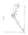
- the target position of the point O 3 which is the external load applied point of the second arm member 10 is set at a point O''3' and the pivoting angles of the first arm member 8 and second arm member 10 for bringing the point 0 3 to the target position O'' 3 are set at 8 1 and ⁇ 2 , respectively, when the first arm member 8 and second arm member 10 are assumed to produce no deflection.
- the first arm member 8 and second arm member 10 produces deflections as described hereinabove.
- the first arm member 8 and second arm member 10 are actually located in position lower than their target positions, and the deflections V1 and V 2 can be obtained by the equations (3) and (4), respectively, as described hereinabove.
- ⁇ 1 ⁇ 1 and ⁇ 2 ⁇ 2 .
- V 1x , V 1y , V 2X and V 2y the x- and y-coordinates of the deflections v 1 and V 2 in the x-y coordinate system which may be denoted by V 1x , V 1y , V 2X and V 2y can be expressed as follows:
- the coordinate values (x i , y i ) of the instantaneous positions are obtained by calculating the difference between the coordinate values (x o , y o ) of the initial positions and the coordinate values (x, y) of the target positions and dividing the difference into N portions. That is, the values of x i , y i are obtained by the following equations:
- ⁇ 1 and ⁇ 2 can be obtained.
- the ⁇ 1 and ⁇ 2 obtained in this way are outputted to the adders 24f and 24g from the correcting angle calculation section 24e.
- the calculation sections 24a-24e and the comparator section 24j of the control unit 24 can be constituted by logical circuits. Also, they can be realized by using a microcomputer. The control unit as a whole can be realized by using a microcomputer.
- step a shown in Fig. 5 the coordinate values (x, y) of the target position indicated by the target position indication device 22 are read out.
- step b the coordinate values (x , y ) of the initial position are calculated based on the outputs ⁇ 1 and ⁇ 2 of the angle gauges E1 and E 2 when a signal indicative of the target position is produced by the device 22.
- step c based on the coordinate values (x, y) of the target position and the coordinate values (x o' y o ) of the initial position, the ith coordinates values (x i' y i ) out of those of the multiplicity of instantaneous target positions on the locus between the initial position and the target position are calculated.
- step d the provisional pivoting angles ⁇ 1r and 6 2r for the first arm member 8 and second arm member 10 for realizing the instantaneous target position (x i , y i ) are calculated.
- the manner of the calculation done in this step is the same as described by referring to the pivoting angle calculation section 24d.
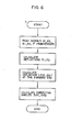
- step e as shown in detail in Fig.
- signals ⁇ 1 , ⁇ 2 , a 1 , a 2 and P produced by the angle gauges E 1 and E 2 , accelerometers A 1 and A 2 and force sensor F are inputted, and, based on the inputted values, calculation is done by using the equations (1) to (4) to obtain the deflections V 1 and V 2 at the points 0 2 and O 3 at the forward ends of the first arm member 8 and second arm member 10 and based on the values of V 1 and V 2 , calculation is done by using the equations (5) and (6) to obtain the deflections Ax and ⁇ y at the forward end O 3 of the second arm member 10.
- step d based on these values and the values of ⁇ 1r and ⁇ 2r obtained in step d calculation is done by using the equations (7) to (10) to obtain correcting angles ⁇ 1 and ⁇ 2 for the first arm member 8 and second arm member 10 corresponding to the deflections ⁇ x and ⁇ y, respectively.
- step f the correcting angles ⁇ 1 and ⁇ 2 are added to the provisional pivoting angles ⁇ 1r and ⁇ 2r to obtain corrected pivoting angles ⁇ 1r + D ⁇ 2 and 6 2r + ⁇ 2
- step g the differences between the signals ⁇ 1 and ⁇ 2 outputted by the angle gauges E 1 and E 2 and the corrected pivoting angles ⁇ 1r + ⁇ 1 and ⁇ 2r + ⁇ 2 are obtained, and whether or not the difference is smaller than the allowance ⁇ a is judged.
- the operation shifts to step h in which a signal corresponding to the differences is outputted to the servomechanism 26 to pivotally move the arms members 8 and 10.
- the signals a 1 and a 2 produced by the accelerometers A 1 and A 2 have been used to obtain angular accelerations ⁇ 1 and ⁇ 2 in the equations (1) and (2) used to calculate deflections at the deflection calculation section 24a.
- the angular accelerations 61 and ⁇ 2 can be also be obtained by twice differentiating the values of the output signals ⁇ 1 and 8 2 of the angle gauges E1 and E 2 .
- the accelerometers A 1 and A 2 can be done without.
- accelerometers had better been used.
- angular velocity meters may be provided to directly obtain the values of the angular velocities ⁇ 1 and ⁇ 2 .
- control of positioning the forward end of the arm assembly 6 is effected to correct errors caused by the deflection of the arm assembly in positioning the forward end of the arm assembly 6 while the first arm member 8 and second arm member 10 are being pivotally moved.
- the invention is not limited to this specific mode of operation.
- the first arm member 8 and second arm member 10 may be made first to be pivotally moved based on signals preduced by the target position indicating device 22 and then, after temperarily stopping the operation of the first arm member 8 and second arm member 10, the positioning error caused by the deflection of the arm assembly 6 may be corrected.
- FIG. 7 shows a positioning control system 30 of another embodiment of the invention for effecting such control.
- a target position indication device 32 and a deflection calculation section 34a, a pivoting angle calculation section 34b a correcting angle calculation section 34c of a control unit 34 are similar to the corresponding parts of the embodiment shown in Fig. 2.
- deflection calculation section 34a deflections are calculated after the first arm member 8 and second arm member 10 have stoped operating, so that no dynamic load is applied.
- the deflection due to the own weight of the arm assembly and the deflection caused by an external load may be separately obtained by a process based on the science of the strength of materials and added to each other without using the equations (1) and (2).
- the control system 30 comprises a correction initiation indication device-36 for indicating initiation of correction by using a signal ⁇ 1 , ⁇ 2 from the correcting angle calculation section 34c after the pivotal movement of the first arm member 8 and second arm member 10 has been stopped.
- the servomechanism 26 is driven by the signal ⁇ 1r , ⁇ 2r from the pivoting angle calculation device 36b before a signal from the correction initiation indication device 36 is supplied, but the servomechanism 26 is driven by the signal A6 1 , ⁇ 2 from the correcting angle calculation section 34c after the signal has been supplied.
- the arm assembly 6 has been described as comprising the first arm member 8 and second arm member 10.
- the invention is not limited to this specific number of arm members, and the arm assembly may comprise three or more than three arm members, for example.
- the arm members 8 and 10 have been described as being driven for pivotal movement by the hydraulic cylinders 12 and 14, respectively. However, this is not restrictive, and any actuators such as hydraulic motors may be used as actuators in place of the hydraulic cylinders 12 and 14.
- the arm members 8 and 10 may be driven, not hydraulically, but pneumatically or electrically as desired.
- the arm assembly 6 is constructed such that an external load is applied only to the forward end of the second arm member 10.
- the invention is not limited to this specific construction of the arm assembly, and the first arm member 8 may support in a predetermined position a deck for an operator to stand and supervise the operation, so that an additional external load is applied to the arm assembly 6 in a portion thereof other than the forward end of the second arm member 10.
- the working apparatus of pliable structure according to the invention is constructed such that the arm assembly can be positioned with a high degree of accuracy and precision by taking into consideration the deflections of the arm members, and this makes the working apparatus of pliable structure according to the invention suitable for use as working apparatus, such as construction machinery, which require elongated arms of light weight.
Landscapes
- Engineering & Computer Science (AREA)
- Robotics (AREA)
- Mechanical Engineering (AREA)
- Manipulator (AREA)
- Jib Cranes (AREA)
- Control Of Position Or Direction (AREA)
- Numerical Control (AREA)
Applications Claiming Priority (2)
| Application Number | Priority Date | Filing Date | Title |
|---|---|---|---|
| JP266370/84 | 1984-12-19 | ||
| JP26637084 | 1984-12-19 |
Publications (3)
| Publication Number | Publication Date |
|---|---|
| EP0188759A2 true EP0188759A2 (fr) | 1986-07-30 |
| EP0188759A3 EP0188759A3 (en) | 1987-10-28 |
| EP0188759B1 EP0188759B1 (fr) | 1993-06-09 |
Family
ID=17429998
Family Applications (1)
| Application Number | Title | Priority Date | Filing Date |
|---|---|---|---|
| EP85116137A Expired - Lifetime EP0188759B1 (fr) | 1984-12-19 | 1985-12-18 | Appareil de manutention de structure pliable |
Country Status (4)
| Country | Link |
|---|---|
| US (1) | US4710884A (fr) |
| EP (1) | EP0188759B1 (fr) |
| JP (1) | JPS61281304A (fr) |
| DE (1) | DE3587396T2 (fr) |
Cited By (2)
| Publication number | Priority date | Publication date | Assignee | Title |
|---|---|---|---|---|
| EP0254211A3 (en) * | 1986-07-22 | 1989-01-04 | Hitachi, Ltd. | Position correcting control system for servomechanism device |
| EP0519081A4 (en) * | 1990-12-28 | 1994-07-13 | Fanuc Ltd | Method of correcting deflection of robot |
Families Citing this family (25)
| Publication number | Priority date | Publication date | Assignee | Title |
|---|---|---|---|---|
| JP2692043B2 (ja) * | 1987-03-28 | 1997-12-17 | 川崎重工業株式会社 | ロボツトの教示データの作成方法 |
| USH869H (en) * | 1988-03-10 | 1991-01-01 | The United States Of America As Represented By The Secretary Of The Air Force | Contact insertion turret end effector |
| JP2719345B2 (ja) * | 1988-03-30 | 1998-02-25 | 豊田工機株式会社 | 力センサを用いた加工制御装置 |
| JP2735126B2 (ja) * | 1988-12-27 | 1998-04-02 | キヤノン株式会社 | ロボットの制御方法及びその制御装置 |
| JPH02198783A (ja) * | 1989-01-23 | 1990-08-07 | Fanuc Ltd | 産業用ロボットの位置決め補正方式 |
| DE4001433A1 (de) * | 1990-01-19 | 1991-07-25 | Zeiss Carl Fa | Korrekturverfahren fuer koordinatenmessgeraete |
| JP2874238B2 (ja) * | 1990-01-23 | 1999-03-24 | 株式会社安川電機 | 多関節形ロボットの制御方法 |
| US5349277A (en) * | 1992-03-12 | 1994-09-20 | Honda Giken Kogyo Kabushiki Kaisha | Control system for legged mobile robot |
| US5311109A (en) * | 1992-03-31 | 1994-05-10 | Honda Giken Kogyo Kabushiki Kaisha | Locomotion control system for legged mobile robot |
| US5535306A (en) * | 1993-01-28 | 1996-07-09 | Applied Materials Inc. | Self-calibration system for robot mechanisms |
| US6316899B1 (en) * | 1994-09-07 | 2001-11-13 | Polytechnic University | Apparatus for reducing vibration inputs to a device and/or for micropositioning |
| US5767648A (en) * | 1996-04-19 | 1998-06-16 | Massachusetts Institute Of Technology | Base force/torque sensor apparatus for the precise control of manipulators with joint friction and a method of use thereof |
| JP3808321B2 (ja) * | 2001-04-16 | 2006-08-09 | ファナック株式会社 | ロボット制御装置 |
| FR2916069B1 (fr) * | 2007-05-11 | 2009-07-31 | Commissariat Energie Atomique | Procede de traitement pour la capture de mouvement d'une structure articulee |
| CN101870110B (zh) * | 2010-07-01 | 2012-01-04 | 三一重工股份有限公司 | 一种机械铰接臂的控制方法及控制装置 |
| JP5383760B2 (ja) * | 2011-09-09 | 2014-01-08 | ファナック株式会社 | ワーク質量測定機能を備えたロボット |
| CN103814279B (zh) * | 2011-09-20 | 2016-06-29 | 株式会社石田 | 质量测量装置 |
| CN102502405A (zh) * | 2011-10-31 | 2012-06-20 | 徐州重型机械有限公司 | 臂架角度检测装置、检测方法及具有该检测装置的起重机 |
| JP5921248B2 (ja) * | 2012-02-16 | 2016-05-24 | キヤノン株式会社 | ロボットの制御装置、ロボット、そのプログラム及びその制御方法 |
| CN102730584B (zh) * | 2012-06-27 | 2014-12-10 | 三一重工股份有限公司 | 起重机主臂保护装置、保护方法和起重机 |
| JP6700669B2 (ja) * | 2015-04-07 | 2020-05-27 | キヤノン株式会社 | 制御方法、ロボット装置、プログラム、記録媒体、及び物品の製造方法 |
| JP6816495B2 (ja) | 2016-12-19 | 2021-01-20 | 株式会社デンソーウェーブ | ロボットのたわみ補正方法、ロボットの制御装置 |
| CN109702742B (zh) * | 2018-12-29 | 2020-06-30 | 深圳市越疆科技有限公司 | 一种机械臂调平方法和装置 |
| WO2023181157A1 (fr) * | 2022-03-23 | 2023-09-28 | 株式会社Fuji | Machine-outil |
| CN116652942A (zh) * | 2023-05-22 | 2023-08-29 | 中国铁建重工集团股份有限公司 | 一种多关节臂架的位姿检测与控制装置和方法 |
Family Cites Families (7)
| Publication number | Priority date | Publication date | Assignee | Title |
|---|---|---|---|---|
| JPS5344746B2 (fr) * | 1974-05-31 | 1978-12-01 | ||
| US4243923A (en) * | 1979-01-22 | 1981-01-06 | Massachusetts Institute Of Technology | Servo-controlled mobility device |
| JPS5769315A (en) * | 1980-10-13 | 1982-04-28 | Fanuc Ltd | Control system of industrial robot |
| US4362978A (en) * | 1980-10-27 | 1982-12-07 | Unimation, Inc. | Control system for manipulator apparatus |
| GB2102590A (en) * | 1981-07-23 | 1983-02-02 | Custom Microdesign | Digital movement controller for automatic multi-axis machines |
| JPS58137585A (ja) * | 1982-02-05 | 1983-08-16 | 株式会社豊田中央研究所 | 工業用ロボツト |
| JPS59107882A (ja) * | 1982-12-09 | 1984-06-22 | 三菱電機株式会社 | ロボツトの制御装置 |
-
1985
- 1985-12-17 US US06/809,908 patent/US4710884A/en not_active Expired - Lifetime
- 1985-12-18 DE DE85116137T patent/DE3587396T2/de not_active Expired - Fee Related
- 1985-12-18 EP EP85116137A patent/EP0188759B1/fr not_active Expired - Lifetime
- 1985-12-19 JP JP60284216A patent/JPS61281304A/ja active Pending
Cited By (3)
| Publication number | Priority date | Publication date | Assignee | Title |
|---|---|---|---|---|
| EP0254211A3 (en) * | 1986-07-22 | 1989-01-04 | Hitachi, Ltd. | Position correcting control system for servomechanism device |
| EP0519081A4 (en) * | 1990-12-28 | 1994-07-13 | Fanuc Ltd | Method of correcting deflection of robot |
| US5418441A (en) * | 1990-12-28 | 1995-05-23 | Fanuc, Ltd. | Deflection correcting method for a robot |
Also Published As
| Publication number | Publication date |
|---|---|
| EP0188759B1 (fr) | 1993-06-09 |
| DE3587396D1 (de) | 1993-07-15 |
| US4710884A (en) | 1987-12-01 |
| DE3587396T2 (de) | 1993-12-16 |
| EP0188759A3 (en) | 1987-10-28 |
| JPS61281304A (ja) | 1986-12-11 |
Similar Documents
| Publication | Publication Date | Title |
|---|---|---|
| EP0188759A2 (fr) | Appareil de manutention de structure pliable | |
| CA1330363C (fr) | Robot | |
| JP7263412B2 (ja) | 駆動装置、ロボット装置、物品の製造方法、制御方法、制御プログラム、記録媒体 | |
| EP0129245B1 (fr) | Procédé et appareil pour commander un robot | |
| US3948093A (en) | Six degree of freedom force transducer for a manipulator system | |
| EP0349291B1 (fr) | Robot avec commande d'outil pour le suivi de déplacement | |
| CA1127265A (fr) | Systeme pour evaluer l'aptitude d'un robot industriel a reproduire une serie de mouvements programmes | |
| EP0364057B1 (fr) | Système de commande de profilage pour une surface courbe donnée | |
| US6343243B1 (en) | Method for determining load parameters for a manipulator | |
| US20130061695A1 (en) | Robot having workpiece mass measurement function | |
| US6721668B1 (en) | Vibration exciting apparatus and vibration testing apparatus for structure using same | |
| US8406921B2 (en) | Method and device for controlling a manipulator | |
| KR19980040121A (ko) | 다축기계의 3차원입체오차측정방법 | |
| Jinno et al. | Development of a force controlled robot for grinding, chamfering and polishing | |
| CN116476056B (zh) | 基于柔性液压机械臂雅可比矩阵的末端力软测量方法 | |
| US6931302B1 (en) | Method for a robot | |
| JPH06143171A (ja) | ロボット | |
| JP3104839B2 (ja) | ロボット診断方法 | |
| JPH08166318A (ja) | 旋回型空力特性計測装置 | |
| Petterson et al. | Parameter-scheduled trajectory planning for suppression of coupled horizontal and vertical vibrations in a flexible rod | |
| JPH1133944A (ja) | マイクロパラレルリンク機構 | |
| Gienger et al. | Design and sensor system of a biped robot | |
| EP0087414A1 (fr) | Procede et moyen de determination de la position d'un bras de travail | |
| RU2252862C1 (ru) | Способ контроля точности контурных перемещений промышленного робота | |
| Lauer et al. | Transputer network controls robot axes |
Legal Events
| Date | Code | Title | Description |
|---|---|---|---|
| PUAI | Public reference made under article 153(3) epc to a published international application that has entered the european phase |
Free format text: ORIGINAL CODE: 0009012 |
|
| AK | Designated contracting states |
Kind code of ref document: A2 Designated state(s): DE FR GB NL |
|
| PUAL | Search report despatched |
Free format text: ORIGINAL CODE: 0009013 |
|
| RHK1 | Main classification (correction) |
Ipc: B25J 9/18 |
|
| AK | Designated contracting states |
Kind code of ref document: A3 Designated state(s): DE FR GB NL |
|
| 17P | Request for examination filed |
Effective date: 19880301 |
|
| 17Q | First examination report despatched |
Effective date: 19891110 |
|
| GRAA | (expected) grant |
Free format text: ORIGINAL CODE: 0009210 |
|
| AK | Designated contracting states |
Kind code of ref document: B1 Designated state(s): DE FR GB NL |
|
| REF | Corresponds to: |
Ref document number: 3587396 Country of ref document: DE Date of ref document: 19930715 |
|
| ET | Fr: translation filed | ||
| PGFP | Annual fee paid to national office [announced via postgrant information from national office to epo] |
Ref country code: NL Payment date: 19931231 Year of fee payment: 9 |
|
| PLBE | No opposition filed within time limit |
Free format text: ORIGINAL CODE: 0009261 |
|
| STAA | Information on the status of an ep patent application or granted ep patent |
Free format text: STATUS: NO OPPOSITION FILED WITHIN TIME LIMIT |
|
| 26N | No opposition filed | ||
| PGFP | Annual fee paid to national office [announced via postgrant information from national office to epo] |
Ref country code: FR Payment date: 19941021 Year of fee payment: 10 |
|
| PGFP | Annual fee paid to national office [announced via postgrant information from national office to epo] |
Ref country code: GB Payment date: 19941208 Year of fee payment: 10 |
|
| PG25 | Lapsed in a contracting state [announced via postgrant information from national office to epo] |
Ref country code: NL Effective date: 19950701 |
|
| NLV4 | Nl: lapsed or anulled due to non-payment of the annual fee |
Effective date: 19950701 |
|
| PG25 | Lapsed in a contracting state [announced via postgrant information from national office to epo] |
Ref country code: GB Effective date: 19951218 |
|
| GBPC | Gb: european patent ceased through non-payment of renewal fee |
Effective date: 19951218 |
|
| PG25 | Lapsed in a contracting state [announced via postgrant information from national office to epo] |
Ref country code: FR Effective date: 19960830 |
|
| REG | Reference to a national code |
Ref country code: FR Ref legal event code: ST |
|
| PGFP | Annual fee paid to national office [announced via postgrant information from national office to epo] |
Ref country code: DE Payment date: 20001211 Year of fee payment: 16 |
|
| PG25 | Lapsed in a contracting state [announced via postgrant information from national office to epo] |
Ref country code: DE Free format text: LAPSE BECAUSE OF NON-PAYMENT OF DUE FEES Effective date: 20020702 |