EP0189046A2 - Vorrichtung zum Schutz des Gasflaschenventils von Stahlflaschen - Google Patents
Vorrichtung zum Schutz des Gasflaschenventils von Stahlflaschen Download PDFInfo
- Publication number
- EP0189046A2 EP0189046A2 EP86100103A EP86100103A EP0189046A2 EP 0189046 A2 EP0189046 A2 EP 0189046A2 EP 86100103 A EP86100103 A EP 86100103A EP 86100103 A EP86100103 A EP 86100103A EP 0189046 A2 EP0189046 A2 EP 0189046A2
- Authority
- EP
- European Patent Office
- Prior art keywords
- protective
- gas cylinder
- neck ring
- ring
- cylinder valve
- Prior art date
- Legal status (The legal status is an assumption and is not a legal conclusion. Google has not performed a legal analysis and makes no representation as to the accuracy of the status listed.)
- Granted
Links
Images
Classifications
-
- F—MECHANICAL ENGINEERING; LIGHTING; HEATING; WEAPONS; BLASTING
- F17—STORING OR DISTRIBUTING GASES OR LIQUIDS
- F17C—VESSELS FOR CONTAINING OR STORING COMPRESSED, LIQUEFIED OR SOLIDIFIED GASES; FIXED-CAPACITY GAS-HOLDERS; FILLING VESSELS WITH, OR DISCHARGING FROM VESSELS, COMPRESSED, LIQUEFIED, OR SOLIDIFIED GASES
- F17C13/00—Details of vessels or of the filling or discharging of vessels
- F17C13/06—Closures, e.g. cap, breakable member
-
- F—MECHANICAL ENGINEERING; LIGHTING; HEATING; WEAPONS; BLASTING
- F17—STORING OR DISTRIBUTING GASES OR LIQUIDS
- F17C—VESSELS FOR CONTAINING OR STORING COMPRESSED, LIQUEFIED OR SOLIDIFIED GASES; FIXED-CAPACITY GAS-HOLDERS; FILLING VESSELS WITH, OR DISCHARGING FROM VESSELS, COMPRESSED, LIQUEFIED, OR SOLIDIFIED GASES
- F17C2205/00—Vessel construction, in particular mounting arrangements, attachments or identifications means
- F17C2205/03—Fluid connections, filters, valves, closure means or other attachments
- F17C2205/0302—Fittings, valves, filters, or components in connection with the gas storage device
- F17C2205/0308—Protective caps
-
- Y—GENERAL TAGGING OF NEW TECHNOLOGICAL DEVELOPMENTS; GENERAL TAGGING OF CROSS-SECTIONAL TECHNOLOGIES SPANNING OVER SEVERAL SECTIONS OF THE IPC; TECHNICAL SUBJECTS COVERED BY FORMER USPC CROSS-REFERENCE ART COLLECTIONS [XRACs] AND DIGESTS
- Y10—TECHNICAL SUBJECTS COVERED BY FORMER USPC
- Y10T—TECHNICAL SUBJECTS COVERED BY FORMER US CLASSIFICATION
- Y10T137/00—Fluid handling
- Y10T137/6851—With casing, support, protector or static constructional installations
- Y10T137/7043—Guards and shields
- Y10T137/7062—Valve guards
Definitions
- the invention relates to a device for protecting the gas bottle valve of steel bottles, which have a threaded neck ring for screwing on the protective device.
- the protective caps are no longer offer reliable protection if the neck thread is corroded and can even be a source of danger. If the neck thread is corroded, it often happens, especially when transporting the steel bottles by hand, that the protective caps slip off and accidents are caused.
- Another disadvantage of the protective caps is that they have to be removed for gas extraction. As a result, the gas sampling valve is not protected during removal. In addition, the removed protective caps are easily lost, especially on construction sites. Your replacement is then expensive. Especially on construction sites, the protective caps also pose a danger in that they are often unscrewed with unsuitable tools.
- the invention has for its object to provide a device for protecting the gas bottle valve of gas bottles, which is safe even with a corroded neck thread and overall allows a simpler and easier handling of the bottle during transport and gas extraction.
- the clamping ring contains a slot in a manner known per se which can be bridged and narrowed by a screw connection.
- the clamping ring screwed onto the neck ring is thus both form-fitting through the screw connection and non-positive due to the clamping connection firmly connected to the steel bottle. If the neck thread is intact, each of these connections already represents a secure connection. If the positive connection fails if the neck thread is corroded, the clamp connection still provides a secure connection between the steel bottle and the protective device. Slipping of the protective device, for example when the bottles are transported by hand, is definitely not possible. Steel bottles with a corroded neck thread can thus also be handled safely when using the protective device according to the invention.
- Another advantage of the device according to the invention can be seen in the fact that the gas cylinder valve remains protected even during gas extraction, since the protective device for gas extraction does not have to be removed. Since the protective device remains screwed on even during gas extraction, there is hardly any possibility that the neck thread will corrode. On the other hand, corroded neck threads can be used without any worries, so there is no longer any need to replace neck rings. A loss of the protective device, for example on construction sites, and the associated transportation of steel bottles with unprotected valves is no longer possible.
- Another advantage of the protective device according to the invention can be seen in the fact that safe crane transport is possible for the first time in gas practice by hanging the protective bracket in the crane hook. The highest region of the protective bracket is advantageously designed as a spherical section. This allows the steel bottle to be easily guided when rolling and gives the user a firm grip.
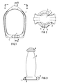
- the protective device shown in Figures 1 to 3 consists essentially of the clamping ring 1 and the protective bracket 2, which are designed as a one-piece casting.
- the clamping ring 1 is provided with the usual neck thread 3 so that it can be screwed onto the neck ring of the steel bottles.
- the clamping ring 1 is divided by a slot 4.
- the two ends of the clamping ring 1 formed by the slot 4 have openings 5 for receiving a screw which compresses the ends of the clamping ring 1 and thereby narrows the slot 4. This creates such a firm, non-positive connection between the clamping ring 1 and the neck ring of the steel bottle that the protective device sits securely on the neck ring, regardless of the condition of the thread of the neck ring.
- the highest area of the protective bracket 2 is designed as a spherical section 6. This is advantageous for the bottle transport by hand, because the steel bottle can be easily guided when rolling with the help of the ball section 6. At the same time, the ball section 6 and the protective bar 2 give the user a firm grip.
- the protective bracket 2 is designed so large that there is still enough space above the gas bottle valve to hang the gas bottle with the protective device in a crane hook.
- the protective device according to the invention does not necessarily have to be designed as a cast construction, even if this is usually the most advantageous, for example made of malleable cast iron, cast steel and cast iron. Welded constructions or composite constructions, in which, for example, the protective bracket is screwed to the clamping ring, are also possible.
Landscapes
- Engineering & Computer Science (AREA)
- Mechanical Engineering (AREA)
- General Engineering & Computer Science (AREA)
- Filling Or Discharging Of Gas Storage Vessels (AREA)
Abstract
Description
- Die Erfindung betrifft eine Vorrichtung zum Schutz des Gasflaschenventils von Stahlflaschen, die einen mit einem Gewinde versehenen Halsring zum Aufschrauben der Schutzvorrichtung besitzen.
- Zum Schutz des Gasflaschenventils von Stahlflaschen wird seit Jahrzehnten eine genormte, glockenförmige Schutzkappe verwendet, die auf den Halsring aufgeschraubt wird und das Ventil von der Umgebung völlig abschirmt. Der Halsring selbst ist in der Öffnung der Stahlflasche befestigt. In ihn wird das Gasflaschenventil eingeschraubt. Diese glockenförmigen Schutzkappen bieten dem Gasflaschenventil zwar einen vollkommenen Schutz, im praktischen Betrieb, vor allem bei der Gasentnahme, haben sie jedoch auch eine Reihe von Nachteilen.
- Einer der schwerwiegendsten Nachteile der Schutzkappen besteht darin, daß sie bei korrodiertem Halsgewinde keinen sicheren Schutz mehr bieten und sogar eine Gefahrenquelle darstellen können. Bei korrodiertem Halsgewinde kommt es immer wieder vor, vor allem beim Handtransport der Stahlflaschen, daß die Schutzkappen abrutschen und hierdurch Unfälle verursacht werden. Ein weiterer Nachteil der Schutzkappen besteht darin, daß sie zur Gasentnahme abgenommen werden müssen. Dadurch ist das Gasentnahmeventil während der Entnahme nicht geschützt. Außerdem gehen die abgenommenen Schutzkappen, vor allem auf Baustellen, leicht verloren. Ihr Ersatz ist dann kostspielig. Vor allem auf Baustellen stellen die Schutzkappen auch dadurch eine Gefahr dar, daß sie oft mit nichtgeeigneten Werkzeugen abgeschraubt werden.
- Der Erfindung liegt die Aufgabe zugrunde, eine Vorrichtung zum Schutz des Gasflaschenventils von Gasflaschen zu schaffen, die auch bei korrodiertem Halsgewinde sicher ist und insgesamt eine einfachere und leichtere Handhabung der Flasche beim Transport und bei der Gasentnahme ermöglicht.
- Ausgehend von dem im Oberbegriff des Anspruches 1 berücksichtigten Stand der Technik ist diese Aufgabe erfindungsgemäß gelöst mit den im kennzeichnenden Teil des Anspruches 1 angegebenen Merkmalen.
- Vorteilhafte Weiterbildungen der Erfindung sind in den Unteransprüchen angegeben.
- Der Klemmring enthält in an sich bekannter Weise einen Schlitz, der durch eine Schraubverbindung überbrückt und verengt werden kann. Der auf den Halsring aufgeschraubte Klemmring ist dadurch sowohl formschlüssig durch die Schraubverbindung als auch kraftschlüssig durch die Klemmverbindung fest mit der Stahlflasche verbunden. Bei intaktem Halsgewinde stellt jede dieser Verbindungen bereits eine sichere Verbindung dar. Wenn bei korrodiertem Halsgewinde die formschlüssige Verbindung ausfällt, ist durch die Klemmverbindung immer noch eine sichere Verbindung zwischen Stahlflasche und Schutzvorrichtung gegeben. Ein Abrutschen der Schutzvorrichtung, beispielsweise beim Handtransport der Flaschen, ist mit Sicherheit ausgeschlossen. Auch Stahlflaschen mit korrodiertem Halsgewinde können somit bei Verwendung der erfindungsgemäßen Schutzvorrichtung sicher gehandhabt werden. Ein weiterer Vorteil der erfindungsgemäßen Vorrichtung ist darin zu sehen, daß das Gasflaschenventil auch während der Gasentnahme geschützt bleibt, da die Schutzvorrichtung zur Gasentnahme nicht abgenommen werden muß. Da die Schutzvorrichtung auch während der Gasentnahme aufgeschraubt bleibt, besteht kaum noch eine Möglichkeit, daß das Halsgewinde korrodiert. Andererseits können korrodierte Halsgewinde unbesorgt weiter verwendet werden, es ist daher keine kostspielige Erneuerung von Halsringen mehr erforderlich. Ein Verlust der Schutzvorrichtung, beispielsweise auf Baustellen, und der damit verbundene Transport von Stahlflaschen mit ungeschützten Ventilen ist nicht mehr möglich. Ein weiterer Vorteil der erfindungsgemäßen Schutzvorrichtung ist darin zu sehen, daß ein sicherer Krantransport durch Einhängen des Schutzbügels in den Kranhaken erstmalig in der Gasepraxis möglich ist. Vorteilhafterweise wird der höchste Bereich des Schutzbügels als Kugelabschnitt ausgebildet. Dadurch läßt sich die Stahlflasche beim Rollen leicht führen und gibt dem Anwender eine feste Griffmöglichkeit.
- Die Zeichnungen veranschaulichen ein Ausführungsbeispiel der Erfindung.
- Es zeigen:
- Fig.1 die Vorderansicht einer erfindungsgemäßen Schutzvorrichtung,
- Fig.2 eine Draufsicht auf die Schutzvorrichtung entsprechend der Linie A-A in Fig.1,
- Fig.3 einen Schnitt durch die Schutzvorrichtung entsprechend der Linie B-B in Fig.1.
- Die in den Fig.1 bis 3 dargestellte Schutzvorrichtung besteht im wesentlichen aus dem Klemmring 1 und dem Schutzbügel 2, welche als einteiliges Gußstück ausgebildet sind. Der Klemmring 1 ist mit dem üblichen Halsgewinde 3 versehen, so daß er auf dem Halsring der Stahlflaschen aufgeschraubt werden kann. An einer Stelle seines Umfanges ist der Klemmring 1 durch einen Schlitz 4 geteilt. Die beiden durch den Schlitz 4 gebildeten Enden des Klemmringes 1 besitzen öffnungen 5 zur Aufnahme einer Schraube, welche die Enden des Klemmringes 1 zusammendrückt und dadurch den Schlitz 4 verengt. Hierdurch wird eine so feste kraftschlüssige Verbindung zwischen Klemmring 1 und Halsring der Stahlflasche geschaffen, daß die Schutzvorrichtung sicher auf dem Halsring aufsitzt, unabhängig vom Zustand des Gewindes des Halsringes.
- Der höchste Bereich des Schutzbügels 2 ist als Kugelabschnitt 6 ausgebildet. Dies ist von Vorteil für den Flaschentransport von Hand, weil die Stahlflasche beim Rollen mit Hilfe des Kugelabschnittes 6 leicht geführt werden kann. Gleichzeitig gibt der Kugelabschnitt 6 und der Schutzbügel 2 dem Anwender eine feste Griffmöglichkeit. Der Schutzbügel 2 wird so groß gestaltet, daß oberhalb des Gasflaschenventils noch genügend Raum bleibt, um die Gasflasche mit der Schutzvorrichtung in einen Kranhaken einzuhängen. Die erfindungsgemäße Schutzvorrichtung muß nicht unbedingt als Gußkonstruktion ausgeführt werden, wenn diese auch in der Regel am vorteilhaftesten ist, z.B. aus Temperguß, Stahlguß und Gußeisen. Schweikonstruktionen oder zusammengesetzte Konstruktionen, bei denen beispielsweise der Schutzbügel mit dem Klemmring verschraubt ist, sind ebenfalls möglich.
Claims (3)
daß die Schutzvorrichtung als auf den Halsring aufschraubbarer Klemmring (1) ausgebildet ist, der einen das Gasflaschenventil umfassenden Schutzbügel (2) aufweist.
dadurch gekennzeichnet,
daß der Schutzbügel in seinem höchsten Bereich oberhalb des Gasflaschenventils als Kugelabschnitt (6) ausgebildet ist.
dadurch gekennzeichnet,
daß Klemmring und Schützbügel als einteiliges Gußstück ausgebildet sind.
Priority Applications (1)
| Application Number | Priority Date | Filing Date | Title |
|---|---|---|---|
| AT86100103T ATE43894T1 (de) | 1985-01-24 | 1986-01-07 | Vorrichtung zum schutz des gasflaschenventils von stahlflaschen. |
Applications Claiming Priority (2)
| Application Number | Priority Date | Filing Date | Title |
|---|---|---|---|
| DE19853502232 DE3502232A1 (de) | 1985-01-24 | 1985-01-24 | Vorrichtung zum schutz des gasflaschenventils von stahlflaschen |
| DE3502232 | 1985-01-24 |
Publications (3)
| Publication Number | Publication Date |
|---|---|
| EP0189046A2 true EP0189046A2 (de) | 1986-07-30 |
| EP0189046A3 EP0189046A3 (en) | 1987-06-03 |
| EP0189046B1 EP0189046B1 (de) | 1989-06-07 |
Family
ID=6260594
Family Applications (1)
| Application Number | Title | Priority Date | Filing Date |
|---|---|---|---|
| EP19860100103 Expired EP0189046B1 (de) | 1985-01-24 | 1986-01-07 | Vorrichtung zum Schutz des Gasflaschenventils von Stahlflaschen |
Country Status (4)
| Country | Link |
|---|---|
| US (1) | US4664286A (de) |
| EP (1) | EP0189046B1 (de) |
| AT (1) | ATE43894T1 (de) |
| DE (1) | DE3502232A1 (de) |
Cited By (5)
| Publication number | Priority date | Publication date | Assignee | Title |
|---|---|---|---|---|
| GB2262156A (en) * | 1991-12-04 | 1993-06-09 | Taymar Ltd | A valve |
| FR2729739A1 (fr) * | 1995-01-25 | 1996-07-26 | Soc D Anciennes Fonderies Et A | Protecteurs pour bouteilles a gaz industriels, domestiques ou medicaux pourvus d'un collier autoserrant de securite |
| WO2012030882A1 (en) * | 2010-09-03 | 2012-03-08 | Praxair Technology, Inc. | Valve guard |
| WO2013156698A1 (fr) * | 2012-04-19 | 2013-10-24 | L'air Liquide,Societe Anonyme Pour L'etude Et L'exploitation Des Procedes Georges Claude | Chapeau de protection pour robinet de bouteille de fluide sous pression et son procédé de fabrication |
| LU92157B1 (fr) * | 2013-02-21 | 2014-08-22 | Presta Gaz S A | Collier pour bouteille de gaz |
Families Citing this family (4)
| Publication number | Priority date | Publication date | Assignee | Title |
|---|---|---|---|---|
| USD334967S (en) | 1989-07-27 | 1993-04-20 | Sakae Kitsuda | Safety cap for gas cylinders |
| US5004117A (en) * | 1989-09-25 | 1991-04-02 | Sakae Kitsuda | Safety cylinder cap |
| FR2791757B1 (fr) * | 1999-04-01 | 2001-06-15 | Air Liquide | Chapeau ouvert composite de grandes bouteilles de gaz industriels et medicaux |
| DE10146261B4 (de) * | 2001-09-20 | 2008-05-29 | Air Liquide Deutschland Gmbh | Ventilschutzbügel |
Family Cites Families (7)
| Publication number | Priority date | Publication date | Assignee | Title |
|---|---|---|---|---|
| FR847127A (de) * | 1939-10-03 | |||
| NL68377C (de) * | ||||
| BE346431A (de) * | 1926-11-19 | |||
| US2234458A (en) * | 1938-01-18 | 1941-03-11 | Underhill Lance | Attachment for containers |
| US3648885A (en) * | 1969-08-05 | 1972-03-14 | Minoru Kitsuda | A cap member for a high-pressure gas container |
| GB1529293A (en) * | 1977-05-25 | 1978-10-18 | Kitsuda M | Protection cap for the valve of a pressure vessel or cylinder |
| US4521676A (en) * | 1982-09-30 | 1985-06-04 | Aga Ab | Encoded cap for a pressurized gas cylinder |
-
1985
- 1985-01-24 DE DE19853502232 patent/DE3502232A1/de active Granted
-
1986
- 1986-01-07 AT AT86100103T patent/ATE43894T1/de active
- 1986-01-07 EP EP19860100103 patent/EP0189046B1/de not_active Expired
- 1986-01-22 US US06/821,440 patent/US4664286A/en not_active Expired - Fee Related
Cited By (8)
| Publication number | Priority date | Publication date | Assignee | Title |
|---|---|---|---|---|
| GB2262156A (en) * | 1991-12-04 | 1993-06-09 | Taymar Ltd | A valve |
| GB2262156B (en) * | 1991-12-04 | 1995-08-30 | Taymar Ltd | A valve |
| FR2729739A1 (fr) * | 1995-01-25 | 1996-07-26 | Soc D Anciennes Fonderies Et A | Protecteurs pour bouteilles a gaz industriels, domestiques ou medicaux pourvus d'un collier autoserrant de securite |
| WO2012030882A1 (en) * | 2010-09-03 | 2012-03-08 | Praxair Technology, Inc. | Valve guard |
| WO2013156698A1 (fr) * | 2012-04-19 | 2013-10-24 | L'air Liquide,Societe Anonyme Pour L'etude Et L'exploitation Des Procedes Georges Claude | Chapeau de protection pour robinet de bouteille de fluide sous pression et son procédé de fabrication |
| FR2989759A1 (fr) * | 2012-04-19 | 2013-10-25 | Air Liquide | Chapeau de protection pour robinet de bouteille de fluide sous pression et son procede de fabrication |
| AU2013250997B2 (en) * | 2012-04-19 | 2017-02-02 | L'air Liquide,Societe Anonyme Pour L'etude Et L'exploitation Des Procedes Georges Claude | Protective cap for a pressurised fluid cylinder valve and production method thereof |
| LU92157B1 (fr) * | 2013-02-21 | 2014-08-22 | Presta Gaz S A | Collier pour bouteille de gaz |
Also Published As
| Publication number | Publication date |
|---|---|
| US4664286A (en) | 1987-05-12 |
| DE3502232C2 (de) | 1988-07-21 |
| ATE43894T1 (de) | 1989-06-15 |
| DE3502232A1 (de) | 1986-07-24 |
| EP0189046B1 (de) | 1989-06-07 |
| EP0189046A3 (en) | 1987-06-03 |
Similar Documents
| Publication | Publication Date | Title |
|---|---|---|
| EP0189046B1 (de) | Vorrichtung zum Schutz des Gasflaschenventils von Stahlflaschen | |
| EP0069866A1 (de) | Verschlusselement für Bohrungen | |
| DE4210383C2 (de) | Klammerartiger Schnellverschluß | |
| DE8501749U1 (de) | Vorrichtung zum Schutz des Gasflaschenventils von Stahlflaschen | |
| DE60116728T2 (de) | Sicherheitsvorrichtung für eine Rohrleitungsarmatur | |
| CH653425A5 (de) | Rohrschelle. | |
| EP0549520B1 (de) | Richtbacken für eine Richtvorrichtung zum Geraderichten von Draht | |
| DE3417600A1 (de) | Verschluss zum halten eines in einen bremsbelagtraeger einschiebbaren bremsbelages fuer scheibenbremsen, insbesondere fuer schienenfahrzeuge | |
| DE9408638U1 (de) | Ventilschutz | |
| EP0693415B1 (de) | Sicherung für einen Königszapfen eines freistehenden Sattelaufliegers für Zugfahrzeuge | |
| DE20103233U1 (de) | Anschlußschraube | |
| DE3329835C1 (de) | Sicherheitsverschluß für zweiteilige Gehäuse zum Filtern von Flüssigkeiten | |
| DE19717916C1 (de) | Spann- und Klemmvorrichtung | |
| DE3243732C2 (de) | Vorrichtung zum Verspannen von Profilsegmenten eines Ausbaurahmens | |
| DE2530597C3 (de) | Verschlußdeckel für Öffnungen in Hohlmasten | |
| DE6924853U (de) | Befestigungsvorrichtung, insbesondere fuer den ausleger eines bauaufzugs an einer gerueststuetze | |
| DE3522396A1 (de) | Klemmkeil fuer bergsteiger | |
| DE9207140U1 (de) | Anschweißband | |
| DE8603270U1 (de) | Vorrichtung zum Halten insbesondere von Rohrschellen | |
| DE7246910U (de) | Klammerschrauben-Verschluß für Filter-Deckel u. ä. für Nuclear-Anlagen | |
| DE338113C (de) | Befestigung von Einsatzschneiden an Bohrstangen mit kreuzfoermigem Profil | |
| DE2217710C2 (de) | Elektrische Reihenklemme, insbesondere Schaltanlagen-Reihenklemme | |
| DE29604624U1 (de) | Fliesenbrechvorrichtung | |
| DE8329671U1 (de) | Verschlussdeckel fuer Pruef- oder Reinigungsoeffnungen von Rohren oder Behaeltern | |
| DE202004006496U1 (de) | Tragbolzen |
Legal Events
| Date | Code | Title | Description |
|---|---|---|---|
| PUAI | Public reference made under article 153(3) epc to a published international application that has entered the european phase |
Free format text: ORIGINAL CODE: 0009012 |
|
| AK | Designated contracting states |
Kind code of ref document: A2 Designated state(s): AT BE CH FR LI NL |
|
| PUAL | Search report despatched |
Free format text: ORIGINAL CODE: 0009013 |
|
| AK | Designated contracting states |
Kind code of ref document: A3 Designated state(s): AT BE CH FR LI NL |
|
| 17P | Request for examination filed |
Effective date: 19871127 |
|
| 17Q | First examination report despatched |
Effective date: 19880610 |
|
| GRAA | (expected) grant |
Free format text: ORIGINAL CODE: 0009210 |
|
| AK | Designated contracting states |
Kind code of ref document: B1 Designated state(s): AT BE CH FR LI NL |
|
| PG25 | Lapsed in a contracting state [announced via postgrant information from national office to epo] |
Ref country code: NL Effective date: 19890607 Ref country code: FR Free format text: THE PATENT HAS BEEN ANNULLED BY A DECISION OF A NATIONAL AUTHORITY Effective date: 19890607 Ref country code: BE Effective date: 19890607 |
|
| REF | Corresponds to: |
Ref document number: 43894 Country of ref document: AT Date of ref document: 19890615 Kind code of ref document: T |
|
| EN | Fr: translation not filed | ||
| NLV1 | Nl: lapsed or annulled due to failure to fulfill the requirements of art. 29p and 29m of the patents act | ||
| PG25 | Lapsed in a contracting state [announced via postgrant information from national office to epo] |
Ref country code: AT Effective date: 19900107 |
|
| PG25 | Lapsed in a contracting state [announced via postgrant information from national office to epo] |
Ref country code: LI Effective date: 19900131 Ref country code: CH Effective date: 19900131 |
|
| PLBE | No opposition filed within time limit |
Free format text: ORIGINAL CODE: 0009261 |
|
| STAA | Information on the status of an ep patent application or granted ep patent |
Free format text: STATUS: NO OPPOSITION FILED WITHIN TIME LIMIT |
|
| 26N | No opposition filed | ||
| REG | Reference to a national code |
Ref country code: CH Ref legal event code: PL |