EP0189175A1 - Ensemble d'arbre d'essuie-glace extensible et contractible - Google Patents
Ensemble d'arbre d'essuie-glace extensible et contractible Download PDFInfo
- Publication number
- EP0189175A1 EP0189175A1 EP86100764A EP86100764A EP0189175A1 EP 0189175 A1 EP0189175 A1 EP 0189175A1 EP 86100764 A EP86100764 A EP 86100764A EP 86100764 A EP86100764 A EP 86100764A EP 0189175 A1 EP0189175 A1 EP 0189175A1
- Authority
- EP
- European Patent Office
- Prior art keywords
- housing
- wiper arm
- contractible
- extensible
- pivot
- Prior art date
- Legal status (The legal status is an assumption and is not a legal conclusion. Google has not performed a legal analysis and makes no representation as to the accuracy of the status listed.)
- Granted
Links
- 230000003534 oscillatory effect Effects 0.000 claims description 19
- 238000009434 installation Methods 0.000 abstract description 8
- 230000000694 effects Effects 0.000 description 5
- 230000001595 contractor effect Effects 0.000 description 2
- 230000000052 comparative effect Effects 0.000 description 1
- 239000000470 constituent Substances 0.000 description 1
- 230000008602 contraction Effects 0.000 description 1
- 125000004122 cyclic group Chemical group 0.000 description 1
- 238000007789 sealing Methods 0.000 description 1
Images
Classifications
-
- B—PERFORMING OPERATIONS; TRANSPORTING
- B60—VEHICLES IN GENERAL
- B60S—SERVICING, CLEANING, REPAIRING, SUPPORTING, LIFTING, OR MANOEUVRING OF VEHICLES, NOT OTHERWISE PROVIDED FOR
- B60S1/00—Cleaning of vehicles
- B60S1/02—Cleaning windscreens, windows or optical devices
- B60S1/04—Wipers or the like, e.g. scrapers
- B60S1/32—Wipers or the like, e.g. scrapers characterised by constructional features of wiper blade arms or blades
- B60S1/34—Wiper arms; Mountings therefor
- B60S1/36—Variable-length arms
- B60S1/365—Variable-length arms the effective length being automatically varied during angular oscillation of the arm
Definitions
- the present invention relates in general to automotive vehicle windshield wipers and more particularly to a windshield wiper arm assembly of the type which extends and contracts as it swings with a pivot so as to attain an increased wipe area.
- a windshield wiper arm assembly of the above described type is known as is disclosed in the Japanese Provisional Utility Model Publication No. 55-1570.
- a disadvantage of the prior art extensible and contractible wiper arm assembly is that its installation on a pivot requires not only a difficult installation work but a delicate adjusting work since its constituent parts need to be installed separately for assemblage and thereafter adjusted so as to make the wiper arm assembly extensible and contractible at a desired timing.
- a novel and improved extensible and contractible wiper arm assembly for a windshield wiper having an oscillatory pivot and a stationary member.
- the wiper arm assembly comprises a housing detachably mountable on the pivot to oscillate therewith, a wiper arm movably installed in the housing, a stationary gear disposed within the housing and concentric with the pivot, means for rotatably supporting the stationary gear on the housing and engageable with the stationary member to prevent rotation of the stationary gear relative to the stationary member, and an oscillatory pinion rotatably mounted on the housing and meshed with the stationary gear, and a linkage installed in the housing and drivingly interconnecting the oscillatory pinion and the wiper arm in such a manner that rotation of the oscillatory pinion causes the wiper arm to move toward and away from the housing.
- the above structure makes it possible to form the wiper arm assembly into a unit prior to installation on the pivot.
- the wiper arm assembly in the form of a unit is readily and efficiently mountable on the pivot.
- the supporting means comprises a one way clutch interposed between the stationary gear and the stationary member to allow the stationary gear to be rotatable in one direction only relative to the stationary member.
- the provision of the one way clutch makes it possible to improve the wipe pattern.
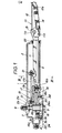
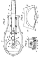
- FIG. 1 generally indicated by the reference numeral 1 is an elongated housing consisting of an upper housing section 2 and a lower housing section 3 which are U-shaped in cross section and fastened together with bolts 4.
- the upper housing section 2 has adjacent an end thereof a boss portion 2a having a serrated opening 2b so that the housing I is detachably mountable at the boss portion 2a on a correspondingly serrated wiper arm drive shaft or pivot 7.
- the housing 1 is mounted on the pivot 7 and fastened thereto with a nut 8. Though not shown, the pivot 7 is drivingly connected to a wiper drive motor to be driven thereby to oscillate in a conventional manner.
- a pair of parallel guide rails 5 are disposed within the housing 1 and secured to the lower housing section 3 with bolts 6.
- a wiper arm 10 is engaged with the guide rails 5 in such a manner as to be movable toward and away from the housing 1, i.e., the wiper arm 10 and the housing 1 are extensible and contractible.
- the wiper arm 10 consists of a main arm section 11 slidably engaged with the guide rails 5 and having at an end disposed outside of the housing 1 an arm head lla, and a sub-arm section 12 disposed outside the housing 1 and pivotally mounted on the arm head 11a of the main arm section 11 by means of a pivot pin 13.
- the sub-arm section 12 carries a wiper blade 30 (refer to Fig.
- the arm head 11a has at a location spaced downward from the pivot pin 13 a spring anchor lIb, and the sub-arm section 12 has at a location intermediate between the opposite ends thereof a spring anchor 12a.
- a spring 14 is disposed between the anchors llb, 12a and attached thereto in a tensioned state so that the wiper blade 30 is urged toward a windshield 31 (refer to Fig. 4) by the bias of the spring 14.
- a wiper drive mechanism generally indicated by the reference numeral 15 is disposed within the housing 1 and consists of a gearing 16 and a linkage 17.
- the gearing 16 consists of a stationary gear 16a and an oscillatory pinion 16b.
- the stationary gear 16a is disposed concentric with the pivot 7 and secured with bolts 9 to a disk 18.
- the disk 18 is in turn mounted on a stationary pivot bearing 9 in the form of an elongated sleeve and secured to same with a key 20 to rotate therewith.
- the pivot bearing 9 is relatively rotatably mounted on the pivot 7 and lockingly engageable at an end thereof with a stationary member such as for example a projection-like member 24a provided to a vehicle body 24.
- the pinion 16b is rotatably mounted on the lower housing section 3 by means of a bolt 23 and meshed with the stationary gear 16a.
- the lower housing section 3 has a boss portion 3a which is formed with a guide opening 3b aligned with the serrated opening 2b of the boss portion 2a of the upper housing section 2.
- the disk 8 has a shoulder 8b at the outer circumferential periphery thereof and is rotatably disposed in the guide opening 3b.
- the guide opening 3b is formed with a stopper 3c which is abuttingly engageable with the shoulder 8b to limit axial movement of the disk 18 inward of the housing 1.
- the stopper 5 is also abuttingly engageable with an end of the stationary gear 16a to limit axial movement of the disk 18 outward of the housing I.
- the linkage 17 consists of an arm 17a integral with the oscillatory pinion 16b and a link 17b extending between a free end of the arm 17a and a portion of the main arm 11 adjacent an inner end thereof and pivotally connected to same with bolts 21 so that rotation of the oscillatory pinion 16b is converted into reciprocating motion of the link 17b and causes the wiper arm 10 to move toward and away from the housing 1.
- Indicated by the reference numeral 22 are a sealing members for providing seals between the disk 18 and the boss portion 3a of the lower housing section 3, between the upper and lower housing sections 2, 3 and between the wiper arm 11 and the housing 1.
- the pivot 7 is driven to oscillate together with the housing 1, causing the oscillatory pinion 16b to roll on the stationary gear 16a in one and the other directions cyclically.
- Rotation of the oscillatory pinion 16b is converted by the linkage 17 into reciprocating motion of the wiper arm 10, thus causing the housing 1 and the wiper arm 10 to extend and contract cyclically.
- Extension and contraction of the wiper arm assembly of the present invention is adapted so that a wipe pattern 32 as shown by the solid lines in Fig. 4 is attained.
- a comparative prior art windshield wiper arm of the inextensible type effects a wipe pattern 33, as indicated by the two-dot-chain lines in Fig. 4, which is part of a ring-shaped area about the pivot 7.
- this embodiment is adapted so that the wiper arm 10 turns about 180° between maximumly rightward and leftward positions in the drawing and that a half cyclic turn (180° turn away from the maximumly rightward position) of the wiper arm 10 causes two turns of the oscillatory pinion 16b on the stationary gear 16a.
- An about 45° turn of the wiper arm 10 away from the maximumly rightward position (maximumly retracted position) therefore causes a half turn of the oscillatory pinion 16b on the stationary gear 16a.
- This causes the joint between arm 17a and the link 17b to turn 180° about the oscillatory pinion 16b and therefore the wiper arm 10 to project maximumly from the housing 1.
- a further about 45° turn of the wiper arm 10 causes the above described joint to return to the former position and therefore the wiper arm 10 to retract maximumly into the housing 1.
- the above action of the wiper arm 10 is repeated during 90° to 180° turning thereof away from the maximumly rightward position.
- the wipe pattern 32 of this embodiment is therefore modified, as compared with the wipe pattern 33 of the inextensible type wiper arm, so as to have two nearly triangular protrusions and increase in wipe area.
- the wiper arm assembly of the present invention can be installed on the pivot 7 easily and efficiently since it is formed into a unit prior to installation on the pivot 7, i.e., the wiper arm 10, gearing 16 and linkage 17 are assembled and installed in the housing 1 which is in turn readily mountable on the pivot 7.
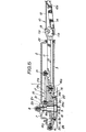
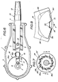
- FIG. 5 to 8 a modified embodiment of the present invention will now be described.
- This embodiment differs from the previous embodiment in that the stationary gear 16a is mounted on a hub portion 18a of the disk 18 by way of a one way clutch 19' so as to rotatable in one direction only relative to the stationary pivot bearing 9, i.e., so as to be rotatable while held stationarily engaged with the oscillatory pinion 16b during turning of the wiper arm 10 away from the maximumly rightward position to the maximumly leftward position (forward turning) and held stationary relative to the pivot bearing 9 during turning of the pivot arm 9 away from the maximumly leftward position to the maximumly rightward position (backward turning).
- a one way clutch 19' so as to rotatable in one direction only relative to the stationary pivot bearing 9, i.e., so as to be rotatable while held stationarily engaged with the oscillatory pinion 16b during turning of the wiper arm 10 away from the maximumly rightward position to the maximumly leftward position (forward turning) and held stationary
- the one way clutch 19' consists of a plurality of ratchet teeth 27 provided to the inner circumferential periphery of the stationary gear 16a, a plurality of balls 26 disposed between the ratchet teeth 24 and the hub portion 18a of the disk 18 and a plurality of springs 25 urging the balls 26 to be driven between the ratchet teeth 24 and the hub portion 18a of the disk 18.
- the one way clutch 19' is adapted so that during forward turning of the wiper arm 10, the stationary gear 16a is urged to rotate in the direction "a” and causes the balls 26 to be driven between the ratchet teeth 27 and the hub portion 18a of the disk 18, thus engaging the clutch 19'.
- the stationary gear 16a is urged to rotate in the direction "b” and allows the balls 26 to slide on the hub portion 18a of the disk 18, thus disengaging the clutch 19'.
- the wiper arm 10 is held in the maximumly retracted state during backward turning of the wiper arm 10 and effects the same extending and contracting action as the previous embodiment during forward turning of the wiper arm 10.
- This embodiment is therefore adapted so that the hatched area 35 in Fig. 8 is wiped by the wiper blade 30 during backward turning of the wiper arm 10.
- the previous embodiment is adapted so that the hatchet area 35 is remained unwiped even during backward turning of the wiper arm 10 since the wiper arm 10 effects the extending and contracting action during not only forward turning but backward turning.
- This embodiment therefore effects a wipe pattern 34 which is further increased in area as compared with that 32 of the previous embodiment.
- this embodiment is substantially similar to the previous embodiment and can produce substantially the same effect.
Landscapes
- Engineering & Computer Science (AREA)
- Mechanical Engineering (AREA)
- Transmission Devices (AREA)
Applications Claiming Priority (4)
| Application Number | Priority Date | Filing Date | Title |
|---|---|---|---|
| JP60009517A JPS61169356A (ja) | 1985-01-22 | 1985-01-22 | 自動車用ワイパ−装置 |
| JP9516/85 | 1985-01-22 | ||
| JP60009516A JPS61169355A (ja) | 1985-01-22 | 1985-01-22 | 自動車用ワイパ−装置 |
| JP9517/85 | 1985-01-22 |
Publications (2)
| Publication Number | Publication Date |
|---|---|
| EP0189175A1 true EP0189175A1 (fr) | 1986-07-30 |
| EP0189175B1 EP0189175B1 (fr) | 1988-12-28 |
Family
ID=26344263
Family Applications (1)
| Application Number | Title | Priority Date | Filing Date |
|---|---|---|---|
| EP86100764A Expired EP0189175B1 (fr) | 1985-01-22 | 1986-01-21 | Ensemble d'arbre d'essuie-glace extensible et contractible |
Country Status (3)
| Country | Link |
|---|---|
| US (1) | US4698873A (fr) |
| EP (1) | EP0189175B1 (fr) |
| DE (1) | DE3661509D1 (fr) |
Cited By (2)
| Publication number | Priority date | Publication date | Assignee | Title |
|---|---|---|---|---|
| EP0288228A1 (fr) * | 1987-04-22 | 1988-10-26 | Champion Spark Plug Europe S.A. | Ensemble de bras d'essuyage pour véhicules à moteur |
| FR2656845A1 (fr) * | 1990-01-11 | 1991-07-12 | Valeo Systemes Dessuyage | Dispositif d'essuyage a balayage non circulaire, notamment pour vehicule automobile. |
Families Citing this family (7)
| Publication number | Priority date | Publication date | Assignee | Title |
|---|---|---|---|---|
| DE3619234A1 (de) * | 1986-06-07 | 1987-12-10 | Bosch Gmbh Robert | Wischanlage fuer scheiben von kraftfahrzeugen |
| DE3624715A1 (de) * | 1986-07-22 | 1988-01-28 | Swf Auto Electric Gmbh | Scheibenwischeranlage, insbesondere fuer kraftfahrzeuge |
| WO1991012158A1 (fr) * | 1990-02-13 | 1991-08-22 | Gregory John Owoc | Appareil de nettoyage de pare-brise |
| DE19501211A1 (de) * | 1995-01-17 | 1996-07-18 | Teves Gmbh Alfred | Wischarm für eine hubgesteuerte Scheibenwischvorrichtung |
| DE69937979T2 (de) * | 1998-04-22 | 2009-01-15 | Mitsuba Corp., Kiryu-shi | Wischeranordnung und Verfahren zum Steuern dieser Anordnung |
| JP4131865B2 (ja) * | 2004-04-06 | 2008-08-13 | 本田技研工業株式会社 | ワイパー装置 |
| US7350259B2 (en) | 2005-07-28 | 2008-04-01 | Tenneco Automotive Operating Company Inc. | Relative axial translation prevention system for wiper blade assemblies |
Citations (4)
| Publication number | Priority date | Publication date | Assignee | Title |
|---|---|---|---|---|
| DE2417128A1 (de) * | 1974-04-09 | 1975-10-23 | Bosch Gmbh Robert | Wischanlage |
| DE3125628C1 (de) * | 1981-06-30 | 1982-12-09 | Daimler-Benz Ag, 7000 Stuttgart | Scheibenwischer,insbesondere Einarmscheibenwischer fuer Kraftwagen |
| FR2548605A1 (fr) * | 1983-07-08 | 1985-01-11 | Rau Swf Autozubehoer | Essuie-glace de pare-brise, specialement pour vehicule a moteur |
| DE3447438A1 (de) * | 1984-12-27 | 1985-05-30 | Friedrich 7300 Esslingen Zikeli | Scheibenwischer-laengshubmechanik mit kreuzschleife- und stirnradplanetgetriebe |
Family Cites Families (3)
| Publication number | Priority date | Publication date | Assignee | Title |
|---|---|---|---|---|
| DE2215307C2 (de) * | 1972-03-29 | 1984-06-20 | Daimler-Benz Ag, 7000 Stuttgart | Scheibenwischeranlage für Fahrzeuge, insbesondere für Kraftwagen |
| DE2430831A1 (de) * | 1974-06-27 | 1976-01-08 | Bosch Gmbh Robert | Wischanlage |
| JPS551570A (en) * | 1978-06-20 | 1980-01-08 | Mitsubishi Electric Corp | Moving object detector |
-
1986
- 1986-01-17 US US06/819,587 patent/US4698873A/en not_active Expired - Fee Related
- 1986-01-21 EP EP86100764A patent/EP0189175B1/fr not_active Expired
- 1986-01-21 DE DE8686100764T patent/DE3661509D1/de not_active Expired
Patent Citations (4)
| Publication number | Priority date | Publication date | Assignee | Title |
|---|---|---|---|---|
| DE2417128A1 (de) * | 1974-04-09 | 1975-10-23 | Bosch Gmbh Robert | Wischanlage |
| DE3125628C1 (de) * | 1981-06-30 | 1982-12-09 | Daimler-Benz Ag, 7000 Stuttgart | Scheibenwischer,insbesondere Einarmscheibenwischer fuer Kraftwagen |
| FR2548605A1 (fr) * | 1983-07-08 | 1985-01-11 | Rau Swf Autozubehoer | Essuie-glace de pare-brise, specialement pour vehicule a moteur |
| DE3447438A1 (de) * | 1984-12-27 | 1985-05-30 | Friedrich 7300 Esslingen Zikeli | Scheibenwischer-laengshubmechanik mit kreuzschleife- und stirnradplanetgetriebe |
Cited By (2)
| Publication number | Priority date | Publication date | Assignee | Title |
|---|---|---|---|---|
| EP0288228A1 (fr) * | 1987-04-22 | 1988-10-26 | Champion Spark Plug Europe S.A. | Ensemble de bras d'essuyage pour véhicules à moteur |
| FR2656845A1 (fr) * | 1990-01-11 | 1991-07-12 | Valeo Systemes Dessuyage | Dispositif d'essuyage a balayage non circulaire, notamment pour vehicule automobile. |
Also Published As
| Publication number | Publication date |
|---|---|
| EP0189175B1 (fr) | 1988-12-28 |
| US4698873A (en) | 1987-10-13 |
| DE3661509D1 (en) | 1989-02-02 |
Similar Documents
| Publication | Publication Date | Title |
|---|---|---|
| US4625359A (en) | Windshield wiper unit | |
| US7257856B2 (en) | Windscreen wiper device, in particular for a motor vehicle | |
| US4698873A (en) | Extensible and contractible wiper arm assembly for windshield wiper | |
| US4765019A (en) | Windshield wiper device and method of setting the same on an automobile | |
| US12134373B2 (en) | Wiping device for a detection system | |
| US4264997A (en) | Wiping arrangement for wiping a vehicle window | |
| US7739771B2 (en) | Windshield wiper drive assembly with dual sector gear drive | |
| CZ2003694A3 (cs) | Pohon stěrače | |
| US5203219A (en) | Speed reducer for a wiper mechanism, having a housing closed by a cover | |
| AU738396B2 (en) | Windshield wiper assembly having a variable speed drive mechanism | |
| US5622077A (en) | Motorized reduction gear unit comprising a hollow casing having a cover plate, especially for a screen wiping apparatus | |
| US5979254A (en) | Motorized reduction gear unit comprising a hollow casing having a cover plate, especially for a screen wiping apparatus | |
| US3831219A (en) | Windscreen wiper | |
| US4815159A (en) | Windshield wiper system for motor vehicles | |
| JP2719608B2 (ja) | ワイパ | |
| US4785491A (en) | Rotary and reciprocating drive device | |
| US4584734A (en) | Windscreen wiper system | |
| US6249929B1 (en) | Windscreen wiper arm | |
| US11364877B2 (en) | Wiper linkage system | |
| US3012266A (en) | Windshield cleaner | |
| US5369837A (en) | Windshield wiper arrangement with an arm of variable active length | |
| US2824332A (en) | Windshield wiper drive mechanism | |
| US2915771A (en) | Windshield wiper transmission and arm assembly | |
| US5090081A (en) | Windshield wiper with variable arcuate pattern | |
| US3003172A (en) | Windshield wiper mechanism |
Legal Events
| Date | Code | Title | Description |
|---|---|---|---|
| PUAI | Public reference made under article 153(3) epc to a published international application that has entered the european phase |
Free format text: ORIGINAL CODE: 0009012 |
|
| 17P | Request for examination filed |
Effective date: 19860121 |
|
| AK | Designated contracting states |
Kind code of ref document: A1 Designated state(s): DE GB |
|
| 17Q | First examination report despatched |
Effective date: 19870824 |
|
| GRAA | (expected) grant |
Free format text: ORIGINAL CODE: 0009210 |
|
| AK | Designated contracting states |
Kind code of ref document: B1 Designated state(s): DE GB |
|
| REF | Corresponds to: |
Ref document number: 3661509 Country of ref document: DE Date of ref document: 19890202 |
|
| PLBE | No opposition filed within time limit |
Free format text: ORIGINAL CODE: 0009261 |
|
| STAA | Information on the status of an ep patent application or granted ep patent |
Free format text: STATUS: NO OPPOSITION FILED WITHIN TIME LIMIT |
|
| 26N | No opposition filed | ||
| PGFP | Annual fee paid to national office [announced via postgrant information from national office to epo] |
Ref country code: GB Payment date: 19950111 Year of fee payment: 10 |
|
| PGFP | Annual fee paid to national office [announced via postgrant information from national office to epo] |
Ref country code: DE Payment date: 19950121 Year of fee payment: 10 |
|
| PG25 | Lapsed in a contracting state [announced via postgrant information from national office to epo] |
Ref country code: GB Effective date: 19960121 |
|
| GBPC | Gb: european patent ceased through non-payment of renewal fee |
Effective date: 19960121 |
|
| PG25 | Lapsed in a contracting state [announced via postgrant information from national office to epo] |
Ref country code: DE Effective date: 19961001 |