EP0189193A2 - Bedingungsteuerungssystem und dafür geeignetes tragbares Prüfgerät - Google Patents
Bedingungsteuerungssystem und dafür geeignetes tragbares Prüfgerät Download PDFInfo
- Publication number
- EP0189193A2 EP0189193A2 EP86100845A EP86100845A EP0189193A2 EP 0189193 A2 EP0189193 A2 EP 0189193A2 EP 86100845 A EP86100845 A EP 86100845A EP 86100845 A EP86100845 A EP 86100845A EP 0189193 A2 EP0189193 A2 EP 0189193A2
- Authority
- EP
- European Patent Office
- Prior art keywords
- control module
- test apparatus
- sensor
- control
- unit
- Prior art date
- Legal status (The legal status is an assumption and is not a legal conclusion. Google has not performed a legal analysis and makes no representation as to the accuracy of the status listed.)
- Withdrawn
Links
Images


Classifications
-
- G—PHYSICS
- G05—CONTROLLING; REGULATING
- G05D—SYSTEMS FOR CONTROLLING OR REGULATING NON-ELECTRIC VARIABLES
- G05D23/00—Control of temperature
- G05D23/19—Control of temperature characterised by the use of electric means
-
- G—PHYSICS
- G06—COMPUTING OR CALCULATING; COUNTING
- G06F—ELECTRIC DIGITAL DATA PROCESSING
- G06F11/00—Error detection; Error correction; Monitoring
- G06F11/22—Detection or location of defective computer hardware by testing during standby operation or during idle time, e.g. start-up testing
- G06F11/26—Functional testing
- G06F11/273—Tester hardware, i.e. output processing circuits
- G06F11/2733—Test interface between tester and unit under test
-
- G—PHYSICS
- G06—COMPUTING OR CALCULATING; COUNTING
- G06F—ELECTRIC DIGITAL DATA PROCESSING
- G06F11/00—Error detection; Error correction; Monitoring
- G06F11/22—Detection or location of defective computer hardware by testing during standby operation or during idle time, e.g. start-up testing
- G06F11/26—Functional testing
- G06F11/261—Functional testing by simulating additional hardware, e.g. fault simulation
Definitions
- These electronic control modules typically contain a microcomputer or microprocessor that in turn operate through a preprogrammed sequence to control a load.
- the load in many cases is a complex type of device, such as a heat pump.
- a typical heat pump contains a reversible refrigeration circuit that is capable of providing both a cooling function and a heating function.
- Most of these units further contain auxiliary heat.
- Auxiliary heat in most cases is a group of electric heaters that can be energized when the heat pump is incapable of supplying sufficient heat to a structure to properly control the temperature within that structure.
- Heat pumps can be manufactured as single units that pass through the wall of a building with the inside unit including an inside heat exchange coil, while the balance of the unit is placed outside and contains an outside heat exchange coil.
- the outside unit further contains equipment such as the compressor, reversing valve, sensors, and expansion means. It is also common to build this type of a system in two separate and distinct parts that are interconnected by refrigerant tubing and electrical connections.
- the typical refrigeration serviceman does not have sufficient background in electronics to be able to properly troubleshoot, diagnose, and service the electronics that are used to control this type of a system.
- the typical heat pump system normally contains a heat pump control module that has all of the electronics, and this module is usually mounted with the outside equipment. When a fault occurs, it is commonplace for the serviceman to replace the heat pump control module. If he finds that this does not solve his problem, many times the new module will be left in place and the old module will be returned to its manufacturer as being defective even though it is not at fault. Some means for quick and easy testing of this module is necessary.
- the invention provides a control system and a test apparatus as characterized in claim 1.
- the microprocessor or microcomputer which controls the normal program sequence of the condition control apparatus is alternatively used during the test run for testing the function of the control module and the condition modifying unit and if desired also of the sensors.
- the control module contains a microcomputer or microprocessor that has at least two preprogrammed sequences.
- the first sequence is the normal program or sequence for the microcomputer or microprocessor to operate a condition modifying unit or heat pump in response to the various sensors and elements of the system along with a condition sensor or room thermostat, and to control the temperature within the space or structure in response to the room thermostat.
- the other preprogrammed sequence that is in the microcomputer or microprocessor is a complete test sequence that will be functional only when an appropriate tester is connected to the entire system.
- the tester can include the necessary switches, simulated sensors in the form of resistors, indicator lights, and power supply means to operate with the control module, the thermostat, and the ambient temperature modifying unit. The tester does not require that it itself has a microprocessor.
- the tester relies on the preprogrammed test sequence built into the microcomputer or microprocessor that is contained in the control module means. With this arrangement, a very simple and inexpensive tester can be provided. This tester relies on the preprogrammed test sequence in the conrol module and thereby avoids the expense of providing the microcomputer or microprocessor within the tester itself.
- a system for control of temperature within a structure with said system being adapted to be tested with a portable test apparatus, including: a thermostat responsive to an ambient temperature within said structure; an ambient temperature modifying unit for said structure with said unit having a plurality of electrical inputs and a plurality of electrical outputs; said inputs and outputs including connection means; said electrical outputs including sensor means outputs from said unit; said electrical inputs including switched power inputs to said unit; control module means having microcomputer means connected by said connection means to said thermostat and said temperature modifying unit to operate said unit in response to said thermostat to control said ambient temperature by said microcomputer providing a preprogramed control sequence for said unit; said microcomputer means further including a preprogramed test sequence; and a portable test apparatus being connected to said sensor means, said electrical inputs, and said control module with said test apparatus replacing said sensor means outputs; said portable test apparatus operating with said microcomputer means to simulate the operation of said unit with said preprogrammed test sequence thereby testing the functional status of said control module
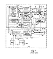
- FIG. 1 discloses a typical condition modifying system in the form of a heat pump.
- a heat pump itself is disclosed at 10.
- the heat pump 10 contains a number of known or standard items such as compressor 11, a contactor control for the compressor 12, a reversing valve 13, the control 14 for the reversing valve, and the piping 15.
- the reversing valve 13 is connected by piping 16 to an outdoor heat exchange coil 17 (which has a fan 19) and the coil 17 in turn is connected by piping 18 to an expansion means 20.
- the expansion means 20 is connected by pipe 21 to an indoor heat exchange coil 22 which in turn is connected through a pipe 23 back to the reversing valve 13.
- the indoor heat exchange coil 22 has a provision at 24 for the forcing of air through the indoor heat exchange coil 22 and through an auxiliary heat generating device 25 such as strip heaters.
- the air flow 24 is provided by a fan 24' to a structure disclosed at 26 that includes a room thermostat or control means 27 that in turn controls fan 24'.
- the heat pump 10 further has a number of sensors such as an outdoor coil temperature sensor 30 and an outdoor air temperature sensor 31.
- a defrost relay 28 completes the heat pump 10 by being connected at 29 and 29' to operate the fan 19 and the control 14 for the reversing valve 13.
- a heat pump control module means generally disclosed at 32.
- This type of module typically would be mounted within the heat pump 10 and contains a microcomputer or microprocessor 33, an analog-to-digital converter 34, and a multiplexer 35.
- the multiplexer 35 is connected at 36 to the microprocessor and has a plurality of inputs.
- One input 37 is from a Low Ambient Compressor Lock Out (L.A.L.O.) potentiometer 38.
- a further input 39 is from a Balance Point (B.P.) potentiometer 40.
- the multiplexer 35 further receives inputs 41 and 42 from the outdoor coil temperature sensor 30 and the outdoor air temperature sensor 31.
- the microprocessor or microcomputer 33 receives a plurality of inputs 43 from the room thermostat 27 and has output 44 to control the compressor 11, output 45 to control the reversing valve 13, output 46 to control the auxiliary heat 25, and output 47 to control the defrost relay 28.
- FIG 2 there is disclosed a heat pump 10 having an inside portion 22' and its outside portion 17'. This heat pump compares to the heat pump of Figure 1.
- a heat pump control or control module 32' mounted within the heat pump 10 is a heat pump control or control module 32'.
- the control module 32' includes the Low Ambient Compressor Lock Out potentiometer 38 and the Balance Point potentiometer 40.
- a microcomputer or microprocessor 33' that is capable of operating the heat pump 10.
- the microcomputer 33' includes a group of five relays 51, 52, 53, 54, and 55. These relays are used to operate contacts that energize three stages of electric heat, the defrost relay 28, and the compressor 11 through conductors contained in the connection means 56 and 56a.
- connection means 56 and 56a have been shown as a solid line connecting in general to the heat pump 10 and identified as a 24 volt alternating current control output from the heat pump control 32'.
- the conductors 56 and 56a include such conductors as 44, 45, 46 and 47.
- the heat pump control or control module 32' further has an indicator light or Light Emitting Diode (LED) 57 that indicates status for the device. Connected to the heat pump control or control module
- the room thermostat 27 which utilizes the conductor 43 to a group of conductors or connection means generally disclosed at 60.
- the conductors at 60 are a means of coupling various circuitry to the heat pump control or control module 32 1 , and to a piece of portable test apparatus that will be discussed subsequently.
- the room thermostat 27 has an indicator LED 58 which operates in conjunction with an indicator light in the portable test apparatus that will now be discussed.
- the portable test apparatus is disclosed at 61 and has a group of electrical connection means 62, 63, and 64 for connection of the portable test apparatus 61 to the heat pump 10, and the heat pump control 32'.
- the terminal 62 can be connected, as shown by the dashed lines 65, to replace the connection of conductor 56a that has been shown as a solid line.
- the solid line conductors 56 and 56a show the normal connection, while the dashed line 65 shows the connection when the tester is in place.
- the connection means 63 is connected by conductors 66 to the sensor inputs of the microprocessor or microcomputer which substitute for the conductors 67 and 67a shown as solid lines.
- connection means 64 is added wherein a pair of conductors 68 and 69 interconnect the portable test apparatus 61 and the connection means 60 of the heat pump control 32'.
- connection means 62, 63, and 64 The function and circuitry related to the connection means 62, 63, and 64 will be explained in connection with Figure 3 where the internal circuit diagram of the portable test apparatus 61 is disclosed in detail.
- the portable test apparatus 61 has a series of eight indicator lights Ll through L8.
- the indicator light L4 is a Light Emitting Diode and the balance of the indicator lights Ll through L3, and L5 through L8 are low voltage light bulbs.
- the portable test apparatus 61 further has an on/off switch S2, a test switch S4, a reset switch S3, and a pair of switches indicated as Sl and S5 that can be ganged together to switch the portable test apparatus 61 between two arbitrary simulated temperature values to test the heat pump control or control module 32' at two fixed points.
- the switch Sl switches fixed impedance means, while the switch S5 performs an internal switching function.
- the switches Sl and S5 could be two separate switches or could be a ganged single switch, as will be shown in connection with Figure 3.
- FIG 3 a circuit diagram of the internal schematic of the portable test apparatus 61 is disclosed. Since the components contained within the portable test apparatus 61 are all conventional in nature, only brief mention will be made of individual components.
- a 120 volt alternating current source is provided to a step down transformer 70 that has a pair of output conductors 71 and 72 to terminals of switch S2.
- the switch S2 can be opened so that the step down transformer 70 is out of the circuit. This is the state when the heat pump 10 and heat pump control 32' supply power to the unit. In some cases that may not be possible and the need to supply operating potentials occur.
- the switch S2 connects to the conductor 71 and 72 thereby connecting a fuse 73 to the light L8 and back across the conductor 71. In this case the light L8 indicates power is available and power is supplied between the conductors 74 and 75 to the overall device.
- the switch Sl is broken down into a group of sections Sla, SIb, and Slc.
- fixed resistors 76 through 81 can be substituted to the heat pump control or control module means 32' to substitute for the sensors that exist in the heat pump 10. This substitution is accomplished through the conductors 66 and 67.
- the switch S3 is a reset switch and it connects a 24 volt conductor (common ground) to the test input for the microprocessor 33 1 to restart a portion of the programmed test sequence contained in the microprocessor or microcomputer 33 1 . The details of this will be brought out in connection with a flow chart of the operation of the device. Also connected in parallel with the switch S3 is a test switch S4 that introduces a fixed resistor 84 across the terminals to which switch S3 are connected.
- each of the functions of the input and output means for the portable test apparatus 61 will be listed and they appear down the right-hand edge of Figure 3.
- Three auxiliary heat connections 86, 87, and 88 are provided. It will be noted that each of the auxiliary heat connections includes a relay contact and these relay contacts are each associated with a single one of the relays 51 through 55 in the heat pump control 32'.
- the system is adapted to be connected to a multiple stage room thermostat and connections 90 and 91 are provided to the first and second stages of a two-stage thermostat (by way of example for the present disclosure).
- a thermostat indicator light connection 92 is provided for the Light Emitting Diode L4 which in turn functions with the indicator light 58 in the thermostat 27.
- a 24 volt common connection 93 is provided along with a test input 94 to the microcomputer or microprocessor 33'.
- a connection 95 is provided to the reversing valve 13, the connection 96 to a pressure switch, and a connection 97 to a common 24 volt alternating current connection.
- the other side of the 24 volt alternating current connection is shown at the power connection 98.
- Two further relay switched conductors 99 and 100 are provided for the defrost relay 28 and the compressor 11 of the heat pump 10.
- the portable test apparatus 61 has a plurality of electrical inputs and a plurality of electrical outputs all of which include connection means.
- the connection means in certain cases are switched power connections, while others are test or sensor connections. The function of each of these will become clearer in connection with the flow charts, and the description of operation of the portable test apparatus 61 with a heat pump 10 and a heat pump control 32'.
- the electrical outputs connected through the conductors 56 to 56a are removed and replaced by connecting the terminals on the conductors 56 (at 65) to the connection means 62.
- Sensor conductors 67a are disconnected and conductors 67 are connected to conductors 66.
- the switch Sl of the tester 61 is set to 100°F (38°C) with the switch S5 automatically set to the "off" position or separately set to the "off” position as indicated in Figure 2. At this point the system is ready to be powered up, and the operation of the system can then be followed from the flow charts of Figures 4 and 5.
- the flow chart of Figure 4 is for In-Field testing of a heat pump 10 and a control module 32', while the flow chart 5 is for use if the device is used as a Factory Tester. There are some differences in the flow charts, and those will be brought out after a description of the flow chart of Figure 2 is provided.
- the system is powered up at 101 and the memory is initialized at 102.
- the system would operate in a normal loop to determine at 104 if all the discrete inputs are at the "off" position. If they are not at the "off” position, the system goes at 104a into a normal control cycle for the heat pump and this control cycle is not of interest as it is not the test cycle. If all the discrete inputs are at the "off" position at 104, the loop continues to check the Low Ambient Compressor Lock Out at 105 to make sure that it is at -10 degrees Fahrenheit. If it is at -10°F (-24°C), the system checks the Balance Point at 106 to make sure that it is set at 45 degrees Fahrenheit.
- the system then checks at 107 to make sure that all of the fixed resistors that simulate sensors have been set to 100° F (38°C). Assuming that the system has been set up properly, light L4 which is a light emitting diode, turns "on" at 108.
- a 60 second timer 109 is started.
- all of the sensors must have been set by the switch S1 to the 20°F (7°C) and at 111 all of the discretes are in the "on" position. If the sequence has progressed properly to this point, the light L4 is indicated at 112 to have gone “off”.
- a 10 second timer is then initiated at 113 and is checked at 114 to have timed out merely as a safety or standby time.
- the light emitting diode L4 then turns “on” at 115, and the 60 cycle timer is started again at 116.
- the system turns "on" the compressor and the auxiliary heat stage 88.
- the timer goes to 20 seconds at 119 and the auxiliary heat stage 87 is turned “on”.
- the timer now increments to 40 seconds at 121 and the defrost relay is turned “on” and auxiliary heat stage 86 is turned “on”.
- the turning on of the defrost relay 99 and the heat stage 86 at 122 is then followed at 123 by the timer reaching 60 seconds.
- the testing is complete and the routine exits from the timer at 124 to the summation point between the power "on” 101 and the initialization of the memory at 102.
- the system also has a reset function 125 that can be activated by the switch S3 to bring the system back into its beginning of operation in case the testing has not been properly done within the allowed time.
- the system is powered down, the portable test apparatus 61 is removed, and all of the original connections for the system are reestablished.
- the Low Ambient Compressor Lock Out potentiometer 38 and the Balance Point potentiometer 40 are reset to their original settings (which were recorded for reference) and the system is then powered up for normal operation.
- a test routine for the same equipment is provided which allows for factory testing at an accelerated rate.
- the accelerated rate utilizes a 5 second timer rather than a 60 second timer 116 of Figure 4 and the outputs to the lights can be read by automatic equipment. With this arrangement, it is possible to test the device at a much faster rate than would be possible in the field where visual indication of the lights status would be required.
- all of the functions 101 through 109 are the same as Figure 4 and will not be reviewed. After the start of the 60 second timer at 109, a determination of the tester having been set up for test purposes is verified at 130.
- the defrost relay 99 is turned “on” and the heat stage 86 is also turned “on”.
- the sequence then continues at 146 with the timer at 5 seconds.
- the system then exits at 147 to the summing point between 101 and 102 where again a reset 125 is available in the event that it becomes necessary to restart this system for test purposes.
- a single microcomputer or microprocessor that is required for operating a complex system, is utilized for two functions.
- the first function is by way of a program to operate the equipment, and the second is by way of a test program that allows a simple piece of test equipment to be added to the system with the benefits of a microprocessor, but lacking the expense and complexity of providing the piece of test equipment with its own microprocessor or microcomputer.
- a tester that is rugged, cheap, and simple to use can be provided for field use by servicemen who might not have the expertise to operate more complex types of testers.
- a specific implementation of the present invention in a heat pump control has been disclosed, but it is quite apparent that the concept could be expanded for other applications.
Landscapes
- Engineering & Computer Science (AREA)
- Physics & Mathematics (AREA)
- General Physics & Mathematics (AREA)
- General Engineering & Computer Science (AREA)
- Theoretical Computer Science (AREA)
- Automation & Control Theory (AREA)
- Computer Hardware Design (AREA)
- Quality & Reliability (AREA)
- Air Conditioning Control Device (AREA)
- Testing And Monitoring For Control Systems (AREA)
- Control Of Temperature (AREA)
Applications Claiming Priority (2)
| Application Number | Priority Date | Filing Date | Title |
|---|---|---|---|
| US69513585A | 1985-01-25 | 1985-01-25 | |
| US695135 | 1985-01-25 |
Publications (1)
| Publication Number | Publication Date |
|---|---|
| EP0189193A2 true EP0189193A2 (de) | 1986-07-30 |
Family
ID=24791726
Family Applications (1)
| Application Number | Title | Priority Date | Filing Date |
|---|---|---|---|
| EP86100845A Withdrawn EP0189193A2 (de) | 1985-01-25 | 1986-01-22 | Bedingungsteuerungssystem und dafür geeignetes tragbares Prüfgerät |
Country Status (2)
| Country | Link |
|---|---|
| EP (1) | EP0189193A2 (de) |
| JP (1) | JPS61175806A (de) |
-
1986
- 1986-01-22 EP EP86100845A patent/EP0189193A2/de not_active Withdrawn
- 1986-01-23 JP JP61011199A patent/JPS61175806A/ja active Pending
Also Published As
| Publication number | Publication date |
|---|---|
| JPS61175806A (ja) | 1986-08-07 |
Similar Documents
| Publication | Publication Date | Title |
|---|---|---|
| US4146085A (en) | Diagnostic system for heat pump | |
| US7562536B2 (en) | Method and apparatus to sense and control compressor operation in an HVAC system | |
| US6826454B2 (en) | Air conditioning diagnostic analyzer | |
| US4246763A (en) | Heat pump system compressor fault detector | |
| US4232530A (en) | Heat pump system compressor start fault detector | |
| US5449274A (en) | Sump system having timed switching of plural pumps | |
| US5316073A (en) | Twinning control | |
| JP3110752B2 (ja) | 液体圧縮を制御する装置 | |
| US4470266A (en) | Timer speedup for servicing an air conditioning unit with an electronic control | |
| US4716520A (en) | Method of checking channel connections and detecting heater circuit and temperature sensor malfunctions in multi-channel closed loop hot melt heating systems | |
| US5816059A (en) | Artificial input controller for HVAC system | |
| US7299111B2 (en) | Method of clearing an HVAC control fault code memory | |
| EP3671058B1 (de) | Wärmepumpen-abtauregelungsvorrichtung und -verfahren | |
| US5834943A (en) | Apparatus and method for sensing failed temperature responsive sensors | |
| US4039932A (en) | Fault indicator testing apparatus | |
| KR910000266B1 (ko) | 냉동장치용 전자 제어 시스템의 현장 시험 방법 | |
| US4716519A (en) | Method of checking channel connections and detecting heater circuit and temperature sensor malfunctions in multi-channel closed loop hot melt heating systems | |
| EP0189193A2 (de) | Bedingungsteuerungssystem und dafür geeignetes tragbares Prüfgerät | |
| EP1567875B1 (de) | Diagnosesystem für elektrische haushaltsgeräte | |
| US5463559A (en) | Diagnostic apparatus for an electronic controller | |
| EP0090757A2 (de) | Kundendienstprüfung für eine elektronische Steuerung | |
| EP0333233B1 (de) | Methode zur Erkennung von Heizkreisfehlern in einem Mehr-Komponenten Heisskleber-Beheizungssystem | |
| CN1266558C (zh) | 制冷装置 | |
| US3246310A (en) | Control and annunciator system | |
| CN221101307U (zh) | 温控器测试系统 |
Legal Events
| Date | Code | Title | Description |
|---|---|---|---|
| PUAI | Public reference made under article 153(3) epc to a published international application that has entered the european phase |
Free format text: ORIGINAL CODE: 0009012 |
|
| AK | Designated contracting states |
Kind code of ref document: A2 Designated state(s): BE CH DE FR GB IT LI NL SE |
|
| ITF | It: translation for a ep patent filed | ||
| STAA | Information on the status of an ep patent application or granted ep patent |
Free format text: STATUS: THE APPLICATION IS DEEMED TO BE WITHDRAWN |
|
| 18D | Application deemed to be withdrawn |
Effective date: 19880802 |
|
| REG | Reference to a national code |
Ref country code: NL Ref legal event code: BC1 |
|
| RIN1 | Information on inventor provided before grant (corrected) |
Inventor name: MUELLER, DALE A. |