EP0189211A2 - Procédé de commutation naturelle pilotée par le réseau ou par la charge - Google Patents
Procédé de commutation naturelle pilotée par le réseau ou par la charge Download PDFInfo
- Publication number
- EP0189211A2 EP0189211A2 EP86100961A EP86100961A EP0189211A2 EP 0189211 A2 EP0189211 A2 EP 0189211A2 EP 86100961 A EP86100961 A EP 86100961A EP 86100961 A EP86100961 A EP 86100961A EP 0189211 A2 EP0189211 A2 EP 0189211A2
- Authority
- EP
- European Patent Office
- Prior art keywords
- trunc
- consumer
- phase
- network
- thyristors
- Prior art date
- Legal status (The legal status is an assumption and is not a legal conclusion. Google has not performed a legal analysis and makes no representation as to the accuracy of the status listed.)
- Granted
Links
Images


Classifications
-
- H—ELECTRICITY
- H02—GENERATION; CONVERSION OR DISTRIBUTION OF ELECTRIC POWER
- H02M—APPARATUS FOR CONVERSION BETWEEN AC AND AC, BETWEEN AC AND DC, OR BETWEEN DC AND DC, AND FOR USE WITH MAINS OR SIMILAR POWER SUPPLY SYSTEMS; CONVERSION OF DC OR AC INPUT POWER INTO SURGE OUTPUT POWER; CONTROL OR REGULATION THEREOF
- H02M5/00—Conversion of AC power input into AC power output, e.g. for change of voltage, for change of frequency, for change of number of phases
- H02M5/02—Conversion of AC power input into AC power output, e.g. for change of voltage, for change of frequency, for change of number of phases without intermediate conversion into DC
- H02M5/04—Conversion of AC power input into AC power output, e.g. for change of voltage, for change of frequency, for change of number of phases without intermediate conversion into DC by static converters
- H02M5/22—Conversion of AC power input into AC power output, e.g. for change of voltage, for change of frequency, for change of number of phases without intermediate conversion into DC by static converters using discharge tubes with control electrode or semiconductor devices with control electrode
- H02M5/25—Conversion of AC power input into AC power output, e.g. for change of voltage, for change of frequency, for change of number of phases without intermediate conversion into DC by static converters using discharge tubes with control electrode or semiconductor devices with control electrode using devices of a thyratron or thyristor type requiring extinguishing means
- H02M5/27—Conversion of AC power input into AC power output, e.g. for change of voltage, for change of frequency, for change of number of phases without intermediate conversion into DC by static converters using discharge tubes with control electrode or semiconductor devices with control electrode using devices of a thyratron or thyristor type requiring extinguishing means for conversion of frequency
- H02M5/271—Conversion of AC power input into AC power output, e.g. for change of voltage, for change of frequency, for change of number of phases without intermediate conversion into DC by static converters using discharge tubes with control electrode or semiconductor devices with control electrode using devices of a thyratron or thyristor type requiring extinguishing means for conversion of frequency from a three phase input voltage
Definitions
- the invention relates to a method for natural, network or consumer-guided commutation of a direct converter, connected between an M-phase network with the frequency F and an m-phase consumer with the frequency f, in particular an electrical machine, the direct converter 2.
- m comprises thyristors that connect each network phase with each consumer phase bidirectionally.
- the circuit there (image 225) comprises in addition to three-phase isolation transformers six fully g e waivete rotary converter bridges with a total of 36 thyristors.
- the circuit there ( Figure 226) comprises three isolating transformers with three triangular-shaped converter bridges with a total of 18 thyristors.
- the invention has for its object to provide a method for natural commutation of a direct converter of the type mentioned that enables a continuous change in the consumer frequency or the consumer voltage from zero to the mains frequency or to the mains voltage.
- the direct converter should be able to be operated with a small number of thyristors without the use of further energy converters (e.g. isolating transformers) to be switched between the network and converter and / or between converter and consumer.
- T X, y and T x, Y denote those thyristors whose anode is electrically connected to the line phase X and whose cathode is connected to the load phase y or whose anode is connected to the load phase x and whose cathode is connected to the line phase Y.
- each network period 1 / F or consumer period 1 / f is each subdivided into a maximum of 2 ⁇ M or 2.
- m are synchronized to the chained voltage u I, II or u 1,2 of the network or consumer. Accordingly, a network synchronization angle PHI and a consumer synchronization angle phi are introduced below.
- u I, II is the instantaneous value of the fundamental oscillation of the chained network voltage, U I, II the amplitude of the chained network voltage between the network phases I and II.
- B is a fixed mesh offset angle (rad.), which is used for the one-time synchronization of PHI with u I, II .
- A stands for the control angle (rad.), Which enables the control of the ratio of the consumer voltage amplitude to the mains voltage amplitude or the current and the power during mains commutation.
- u 1,2 are the instantaneous value of the fundamental oscillation of the chained consumer voltage
- U 1'2 the amplitude of the chained consumer voltage between consumer phases 1 and 2.
- beta is the fixed consumer offset angle (rad.) and is used for one-time synchronization of phi with u 1 , 2 .
- the control angle alpha (rad.) Is used to control the ratio of the consumer voltage amplitude to the mains voltage amplitude or the current and power for consumer commutation.
- the two thyristors T X , y and T x, Y are released for ignition.
- the ignition itself takes place at the beginning of the overlap period.
- the above algorithm which is intended to illustrate the principle of a feature according to the invention, but not as an executable computer program, enables the determination of the network phases X and Y, which are to be connected to the corresponding consumer phases y and x via interposed thyristors.
- Equation (3) can be determined by using y instead of X or x instead of Y in the above algorithm. Furthermore, m, j, f and phi are to be used instead of M, J, F and PHI.
- the commutation method according to the invention can thus e.g. can be implemented by means of two computer programs running independently of one another or by means of two almost identical computer circuits which, based on largely the same algorithmic structure, calculate the network-synchronized and the consumer-synchronized commutation.
- the sizes marked with lower case letters are to be used instead of the sizes marked with upper case letters.
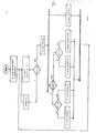
- the determination of the network or consumer period interval J or j as a function of the corresponding synchronization angle can be seen in particular from the flow chart.
- the method according to the invention is accessible to a tendon according to a further advantageous embodiment:
- the numbers X, Y or x, y are increased or decreased by the number N, the numbers x, y by n.
- n and N are positive integers between zero and essentially half of the number of network phases or consumer phases.
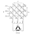
- Figure 1 shows the circuit of the direct converter for an M-phase network and an m-phase consumer.
- the current-carrying thyristor pair T X, y and T x, Y is clearly highlighted by means of black symbols.
- the ignition conditions of the individual thyristors can be determined as a function of the network or consumer synchronization angle PHI or phi.
- blocking times tau can also be introduced in the exemplary embodiments for the case of line-commutation, the upper time limit of the consumer period interval j being reduced by tau, with the result that the time period for the firing of thyristors is reduced.
- the consumer voltage can be controlled by shifting the network synchronization angle PHI with respect to the fundamental oscillation of the chained network voltage u I, II , by changing the control angle A in accordance with equation (2) above in conjunction with equation (1) above.
- the output voltage was reduced in accordance with the output frequency, since this relation is typical for the operation of electrical induction machines.
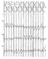
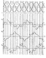
- the vertical, dashed lines and the four time axes crossing in Figures 3 and 4 indicate the ignition times of the corresponding thyristors, whereby the blocking time tau was taken into account to reduce the harmonic content of the currents.
- the voltage or current curves achieved at f F run according to. Figure 6.
- the proposed commutation method should preferably be applied to a polygonally connected consumer. In such a case, the currents run in the consumer windings of the delta connection according to. Figure 2 (i 1,2 , i2,3 and i3 , 1 ) roughly as shown in Figure 6 g e- .
- the thyristors to be fired always have a positive anode-cathode voltage if the load phase angle psi is less than 60 °, ie its cosine is greater than 0.5.
- the advantage achieved with this is there in particular in that for wide areas of electrical drive technology (e.g.
- the converter operated with the method according to the invention does not require a device for detecting the current direction, unlike in all previously known direct converters with natural commutation, which, for example, use HALL-Wand-1s for current direction detection.
Landscapes
- Engineering & Computer Science (AREA)
- Power Engineering (AREA)
- Ac-Ac Conversion (AREA)
- Control Of Direct Current Motors (AREA)
Priority Applications (1)
| Application Number | Priority Date | Filing Date | Title |
|---|---|---|---|
| AT86100961T ATE68642T1 (de) | 1985-01-24 | 1986-01-24 | Verfahren zur natuerlichen, netz- oder verbrauchergefuehrten kommutierung. |
Applications Claiming Priority (2)
| Application Number | Priority Date | Filing Date | Title |
|---|---|---|---|
| DE3502204 | 1985-01-24 | ||
| DE19853502204 DE3502204A1 (de) | 1985-01-24 | 1985-01-24 | Direktumrichter mit natuerlicher kommutierung |
Publications (3)
| Publication Number | Publication Date |
|---|---|
| EP0189211A2 true EP0189211A2 (fr) | 1986-07-30 |
| EP0189211A3 EP0189211A3 (en) | 1987-10-14 |
| EP0189211B1 EP0189211B1 (fr) | 1991-10-16 |
Family
ID=6260571
Family Applications (1)
| Application Number | Title | Priority Date | Filing Date |
|---|---|---|---|
| EP86100961A Expired - Lifetime EP0189211B1 (fr) | 1985-01-24 | 1986-01-24 | Procédé de commutation naturelle pilotée par le réseau ou par la charge |
Country Status (3)
| Country | Link |
|---|---|
| EP (1) | EP0189211B1 (fr) |
| AT (1) | ATE68642T1 (fr) |
| DE (2) | DE3502204A1 (fr) |
Families Citing this family (3)
| Publication number | Priority date | Publication date | Assignee | Title |
|---|---|---|---|---|
| DE3913675C1 (en) * | 1989-04-26 | 1990-01-11 | Georg Dipl.-Ing. 8000 Muenchen De Hienz | Commutating arrangement, for frequency converter - has thyristors galvanically connected in pairs and antiparallel to each mains and consumer phase |
| DE19746797B4 (de) * | 1997-10-23 | 2012-05-24 | Siemens Ag | Verfahren zur Steuerung bidirektionaler Schalter in Stromrichtern |
| DE10051222A1 (de) * | 2000-10-16 | 2002-04-25 | Alstom Switzerland Ltd | Verfahren zum Betrieb eines Matrixkonverters sowie Matrixkonverter zur Durchführung des Verfahrens |
Family Cites Families (2)
| Publication number | Priority date | Publication date | Assignee | Title |
|---|---|---|---|---|
| US3585489A (en) * | 1969-06-20 | 1971-06-15 | Westinghouse Electric Corp | A low-frequency ac reference generator with inherently balanced controllable output voltage |
| EP0124302A3 (fr) * | 1983-04-06 | 1986-02-19 | Texas Instruments Incorporated | Convertisseur d'alimentation à courant alternatif |
-
1985
- 1985-01-24 DE DE19853502204 patent/DE3502204A1/de active Granted
-
1986
- 1986-01-24 AT AT86100961T patent/ATE68642T1/de not_active IP Right Cessation
- 1986-01-24 DE DE8686100961T patent/DE3681926D1/de not_active Expired - Lifetime
- 1986-01-24 EP EP86100961A patent/EP0189211B1/fr not_active Expired - Lifetime
Also Published As
| Publication number | Publication date |
|---|---|
| DE3502204A1 (de) | 1986-08-14 |
| EP0189211B1 (fr) | 1991-10-16 |
| DE3502204C2 (fr) | 1988-02-25 |
| EP0189211A3 (en) | 1987-10-14 |
| DE3681926D1 (de) | 1991-11-21 |
| ATE68642T1 (de) | 1991-11-15 |
Similar Documents
| Publication | Publication Date | Title |
|---|---|---|
| DE2151589C2 (de) | Anordnung zur Steuerung der Drehzahl eines dreiphasigen Drehstrommotors | |
| EP0334112B1 (fr) | Machine à induction actionnée au moyen d'un convertisseur à impulsions | |
| EP1336241B1 (fr) | Procede de commande d'un convertisseur matriciel | |
| DE2225609C2 (de) | Anordnung zur Steuerung der Drehzahl eines über einen statischen Umrichter mit variabler Spannung und dazu etwa mit proportionaler Frequenz gespeisten Mehrphasenwechselstrom-Asynchronmotors | |
| DE2224830A1 (de) | Vielseitig verwendbare Leistungskonverter mit einer Hochfrequenz verbindung | |
| WO2006000111A1 (fr) | Circuit commutateur polyphase pauvre en oscillations harmoniques | |
| DE2106310A1 (de) | Mehrphasen Leistungskonverterschaltung | |
| EP2034606B1 (fr) | Procédé destiné au fonctionnement d'une machine électrique rotative | |
| EP0373381B1 (fr) | Procédé de commande d'un onduleur triphasé | |
| DE3107654C2 (de) | Teilwicklungsschaltung zum Anfahren eines Drehstrommotors | |
| EP0189211B1 (fr) | Procédé de commutation naturelle pilotée par le réseau ou par la charge | |
| DE60132418T2 (de) | Verfahren und System zur Nullstrompegeldetektion in einem netzseitig-kommutierten Umrichter | |
| DE2030107A1 (fr) | ||
| DE2050787C3 (de) | Brückenwechselrichter mit Gleichstromkommutierung | |
| DE3035305C2 (de) | Wechselrichterschaltung für einen Dreiphasen-Synchronmotor | |
| DE2653871A1 (de) | Spannungsgenerator | |
| EP3531547B1 (fr) | Circuit de commande permettant de coupler une machine synchrone avec un réseau de tension et procédé de fonctionnement dudit circuit | |
| DE3014352A1 (de) | Schaltungsanordnung fuer ein- oder mehrphasige elektrische maschinen | |
| DE2909686C2 (fr) | ||
| DE2931878C2 (de) | Schaltungsanordnung zur Drehzahlregelung eines Dreiphasen-Asynchronmotors | |
| EP3853058A1 (fr) | Dispositif de commande conçu pour un onduleur, onduleur conçu pour un véhicule, véhicule et procédé pour faire fonctionner un onduleur | |
| DE1268264B (de) | Drehzahlgesteuerte Stromrichtermaschine | |
| DE2339809C3 (de) | Anordnung zur Steuerung der Drehzahl eines über Thyristoren gesteuerten Drehstrom-Synchronmotors | |
| AT349578B (de) | Steuerschaltung fuer einen in der drehzahl einstellbaren, kommutatorlosen induktionsmotor | |
| AT376531B (de) | Selbstgefuehrter mehrpuls-stromrichter |
Legal Events
| Date | Code | Title | Description |
|---|---|---|---|
| PUAI | Public reference made under article 153(3) epc to a published international application that has entered the european phase |
Free format text: ORIGINAL CODE: 0009012 |
|
| AK | Designated contracting states |
Kind code of ref document: A2 Designated state(s): AT CH DE FR GB LI |
|
| PUAL | Search report despatched |
Free format text: ORIGINAL CODE: 0009013 |
|
| AK | Designated contracting states |
Kind code of ref document: A3 Designated state(s): AT CH DE FR GB LI |
|
| 17P | Request for examination filed |
Effective date: 19871210 |
|
| 17Q | First examination report despatched |
Effective date: 19900314 |
|
| GRAA | (expected) grant |
Free format text: ORIGINAL CODE: 0009210 |
|
| AK | Designated contracting states |
Kind code of ref document: B1 Designated state(s): AT CH DE FR GB LI |
|
| PG25 | Lapsed in a contracting state [announced via postgrant information from national office to epo] |
Ref country code: GB Effective date: 19911016 |
|
| REF | Corresponds to: |
Ref document number: 68642 Country of ref document: AT Date of ref document: 19911115 Kind code of ref document: T |
|
| REF | Corresponds to: |
Ref document number: 3681926 Country of ref document: DE Date of ref document: 19911121 |
|
| PG25 | Lapsed in a contracting state [announced via postgrant information from national office to epo] |
Ref country code: AT Effective date: 19920124 |
|
| PG25 | Lapsed in a contracting state [announced via postgrant information from national office to epo] |
Ref country code: LI Effective date: 19920131 Ref country code: CH Effective date: 19920131 |
|
| EN | Fr: translation not filed | ||
| PG25 | Lapsed in a contracting state [announced via postgrant information from national office to epo] |
Ref country code: FR Effective date: 19920306 |
|
| GBV | Gb: ep patent (uk) treated as always having been void in accordance with gb section 77(7)/1977 [no translation filed] | ||
| PLBE | No opposition filed within time limit |
Free format text: ORIGINAL CODE: 0009261 |
|
| STAA | Information on the status of an ep patent application or granted ep patent |
Free format text: STATUS: NO OPPOSITION FILED WITHIN TIME LIMIT |
|
| REG | Reference to a national code |
Ref country code: CH Ref legal event code: PL |
|
| PG25 | Lapsed in a contracting state [announced via postgrant information from national office to epo] |
Ref country code: DE Effective date: 19921001 |
|
| 26N | No opposition filed | ||
| REG | Reference to a national code |
Ref country code: FR Ref legal event code: ST |