EP0189231A1 - Ecran pour protéger les yeux contre la lumière intense tel qu'un masque à soudure - Google Patents
Ecran pour protéger les yeux contre la lumière intense tel qu'un masque à soudure Download PDFInfo
- Publication number
- EP0189231A1 EP0189231A1 EP86200078A EP86200078A EP0189231A1 EP 0189231 A1 EP0189231 A1 EP 0189231A1 EP 86200078 A EP86200078 A EP 86200078A EP 86200078 A EP86200078 A EP 86200078A EP 0189231 A1 EP0189231 A1 EP 0189231A1
- Authority
- EP
- European Patent Office
- Prior art keywords
- screen
- switch
- shield
- protective shield
- guides
- Prior art date
- Legal status (The legal status is an assumption and is not a legal conclusion. Google has not performed a legal analysis and makes no representation as to the accuracy of the status listed.)
- Withdrawn
Links
- 230000001681 protective effect Effects 0.000 title claims description 21
- 239000011521 glass Substances 0.000 claims abstract description 14
- 230000002441 reversible effect Effects 0.000 claims abstract description 4
- 238000003466 welding Methods 0.000 claims description 4
- 230000005540 biological transmission Effects 0.000 claims description 2
- 230000037431 insertion Effects 0.000 claims 1
- 238000003780 insertion Methods 0.000 claims 1
- 210000003811 finger Anatomy 0.000 description 11
- 238000011109 contamination Methods 0.000 description 2
- 230000000994 depressogenic effect Effects 0.000 description 2
- 239000000463 material Substances 0.000 description 2
- 229920003023 plastic Polymers 0.000 description 2
- 239000004033 plastic Substances 0.000 description 2
- 241000397426 Centroberyx lineatus Species 0.000 description 1
- 238000004140 cleaning Methods 0.000 description 1
- 230000000881 depressing effect Effects 0.000 description 1
- 239000013013 elastic material Substances 0.000 description 1
- 230000002349 favourable effect Effects 0.000 description 1
- 239000012530 fluid Substances 0.000 description 1
- 210000004247 hand Anatomy 0.000 description 1
- 210000003128 head Anatomy 0.000 description 1
- 239000002184 metal Substances 0.000 description 1
- 230000002093 peripheral effect Effects 0.000 description 1
- 239000004753 textile Substances 0.000 description 1
- 210000003813 thumb Anatomy 0.000 description 1
Images
Classifications
-
- A—HUMAN NECESSITIES
- A61—MEDICAL OR VETERINARY SCIENCE; HYGIENE
- A61F—FILTERS IMPLANTABLE INTO BLOOD VESSELS; PROSTHESES; DEVICES PROVIDING PATENCY TO, OR PREVENTING COLLAPSING OF, TUBULAR STRUCTURES OF THE BODY, e.g. STENTS; ORTHOPAEDIC, NURSING OR CONTRACEPTIVE DEVICES; FOMENTATION; TREATMENT OR PROTECTION OF EYES OR EARS; BANDAGES, DRESSINGS OR ABSORBENT PADS; FIRST-AID KITS
- A61F9/00—Methods or devices for treatment of the eyes; Devices for putting in contact-lenses; Devices to correct squinting; Apparatus to guide the blind; Protective devices for the eyes, carried on the body or in the hand
- A61F9/04—Eye-masks ; Devices to be worn on the face, not intended for looking through; Eye-pads for sunbathing
- A61F9/06—Masks, shields or hoods for welders
- A61F9/061—Masks, shields or hoods for welders with movable shutters, e.g. filter discs; Actuating means therefor
-
- Y—GENERAL TAGGING OF NEW TECHNOLOGICAL DEVELOPMENTS; GENERAL TAGGING OF CROSS-SECTIONAL TECHNOLOGIES SPANNING OVER SEVERAL SECTIONS OF THE IPC; TECHNICAL SUBJECTS COVERED BY FORMER USPC CROSS-REFERENCE ART COLLECTIONS [XRACs] AND DIGESTS
- Y10—TECHNICAL SUBJECTS COVERED BY FORMER USPC
- Y10S—TECHNICAL SUBJECTS COVERED BY FORMER USPC CROSS-REFERENCE ART COLLECTIONS [XRACs] AND DIGESTS
- Y10S200/00—Electricity: circuit makers and breakers
- Y10S200/02—Body attached switches
Definitions
- This invention relates to a protective shield to protect the eyes against vivid light, such as a welders mask, helmet or window, with an only slightly transparent screen such as a welding glass, with means for moving this screen by an electric motor to make it slide in its own plane between a position in a light transparent opening in the body of the shield and a position to free said opening for light transmission therethrough and to a hand switch particularly adapted for use therewith.
- Such a shield is known, e.g. from US patent specification 3,833,936.
- an electric motor mounted in the body of the shield with its axis parallel to the direction of movement of the screen.
- a gear train with bevelled and other gear wheels connects the drive spindle of this motor to two pinions one at each side of the screen and each one in engagement with a toothed rack on the screen at the same side thereof.
- This mechanism is rather complicated and comprises a considerable number of rather expensive parts, there have to be two racks and the mechanism is vulnerable as to contamination, in particular between the several gear wheels, which would cause stiff running. There is much friction between the screen and its guides. All this means that relatively high energy requirements have to be met.
- This invention aims at improving such protective shields with respect to the considerations given above and to this end such a shield is, according to the invention, characterized in that the electric motor has a toothed or friction pinion in direct contact with a toothed or friction rack on the screen, the guide means in the shield along at least one of said edges being taken up in the shield in a manner so as to be easily detachable therefrom.
- the invention also relates to details of the guide and drive means as will be explained below.
- the electric motor is also easily removable and insertable by being taken up by a carrier, which is slidable frictionally in guides in the body of the shield so as to be easily removable from and insertable into the shield.
- a protective shield according to the invention is preferably characterized in that the screen has.a protruding part close to each end thereof as seen in its sliding direction, there being a switch in the shield body cooperating with said protruding parts so that, when the screen reaches one end position, one of the protruding parts contacts said switch to move it into one position and when said screen reaches the other end position the other protruding part moves the switch into the other position, said switch being taken up in an electric circuit to energize the electric motor to move the screen, there being a two-way switch operable by the user, taken up with said switch in the shield body, also being a two-way switch, in a double throw circuit in the opposite energizing leads for the reversible electric motor, so that the motor is de - energized in each terminal position of one of the switches in one of the terminal positions of the other switch which, when put in its other terminal position, energizes the
- a hand operated electric switch is according to the invention preferred over other types of switches, such as foot or mouth operated switches giving difficulties as to hindrance, space available inside or outside the shield, hygiene and risk of wrong operation by disturbing factors. But also hand operated switches give problems.
- the user e.g. the welder, also has to use his hands for other purposes, such as for the welding itself, for keeping his own body in the desired position, for positioning workpieces, for operating a light hammer to remove scales from the weld etc.
- the concerning switch may be carried by the shield, e.g. the welder's mask, or by an electrode holder or other part which the user has to handle.
- This invention also aims at bringing improvement in these respects and in view thereof it is according to the invention preferred to use a hand operated switch having a switch body and a brace, with a space between them adapted to take up a human finger between the switch body and the brace for carrying the switch by said finger.
- Such a switch may have a switch body which is so flat, narrow and thin that a working glove may be worn over it without discomfort.
- the brace may even form an inherent part of a glove.
- the brace may be rigid or flexible. In both cases it is preferred to choose sizes and shapes for brace and switch body so that the space between brace and switch body is so narrow and/or of such a shape that the switch has two comfortable equilibrium positions, one in which the feeling side of the finger rests on the switch body and the other one having the switch body on the back side of the finger, the switch being turnable on the finger between these position. With the switch at the back of the finger it is possible for the user e.g. to use a hammer or other tool requiring the exertion of forces thereon by hand without operating the switch.
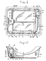
- Casing 1 has a rectangular opening with edge 2.
- the opening is closed by a transparent spatter glass 4 enclosed between L-shaped guides 3 at the outside of casing 1.
- Resilient strips 13 urge the glass 4 resiliently forwardly into contact with the front edges of the guides 3.
- the guide edges 3 are interrupted so that the glass 4 may easily be moved slidingly out of the mask in order to be cleaned or replaced by another glass.
- the resilient strips 13 and the space within the L-shaped guides 3 allow spatter glass (or plastics) plates 4 of different thicknesses to be used.
- the closed face of the casing 1 may carry a series of solar cells not shown in Figs 1 and 2 but indicated as 40 in Fig.
- spatter glass 4 for charging a chargeable battery 27 to be described, and these solar cells may be protected by the same spatter glass 4, then having a much larger surface (height in Fig. 1), or by a separate spatter glass, which may be guided by similar guides as the guides 3 in the same way as glass 4, also being urged forwardly by resilient strips 13 in said guides and removable and replaceable by sliding through the open end of the guides 3 as described for glass 4.
- an only slightly transparent screen 5 such as a welder's glass, movable up and down (in Fig. 1) from a position to leave the opening 2 entirely free (as in Fig. 1) to a position to cover this opening entirely and thus protect the eyes of the welder during welding.
- This screen 5 is connected to guide rods 6a and 6b. Thereto the right hand edge of this screen (in Fig. 1) carries a fork 8 engaging with its tongs one to each side of rod 6a, said fork being part of a strip 9 connected to screen 5.
- each rod 6a, 6b has a supporting bracket 16a, 16b, 16c, 16d, frictionally taken up between two opposite take-up parts 17a, 17b, 17c, 17d, rigidly united with casing 1.
- the brackets 16a to d may be snapped into the space between each two take-up parts 17a to d and be removed therefrom under friction by movements perpendicularly to the plane of Fig. 1.
- a reversible electric motor 15 is taken up between the top leg 18 and the bottom leg 19 of a carrier taken up frictionally for up and down movement (as seen in Fig. 1) between the swallow-tail guides of a carrier part 20 in casing 1.
- Leg 19 also carries a two-way slide switch 23.
- the slidable operating part 24 thereof is operated by protrusions 25, one at each end (upper and lower end as seen in Fig. 1) of the screen 5. These protrusions are preferably somewhat elastic or covered with elastic material to operate switch 23 more flexibly.
- Electric leads 26 connect this switch to the electric system and the electric motor is connected by electric leads 21 to this system in a manner to be described below.
- the spindle 14 of the electric motor 15 carries a pinion 12, which is in driving engagement with a toothed rack 11 integral with strip 10 on screen 5.
- a chargeable battery 27 is taken up slidingly between guides 28 in casing 1 and is taken up in the electric circuit by electric leads 29. Battery 27 can be moved by sliding between those guides so as to be removed, cleaned and replaced easily.
- the screen 5 has top and bottom edges, which are thickened so as to protrude somewhat in the direction of the eye when looking at Fig. 1. When the screen is in the top or bottom position, one of these strips engages over one of these thickened edges to arrest the screen, which is particularly useful to prevent the screen from falling down when in the top position.
- the electric motor 15 may be so as to help in keeping the screen in position by magnetical positioning of its rotor, but as a very light electric motor is sufficient, it is better not to rely thereon fully for such arresting.
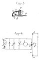
- brace 33 is substantially rigid, it is preferably of oval shape, wider than high, so that the brace fits the finger but can be turned round thereon to have switch casing 31 and button 32 rest either at the back (top) side of the finger or at the touch side thereof. Also when the brace 33 is flexible, those two positions may be stable in view of the rather flat form of switch body 31 as the human fingers perpendicularly to the nail are thinner than in the width direction.
- the motor 15 In the position shown the motor 15 is energized because a circuit is closed through switch 31 and the sliding switch 23 in the casing 1 and through battery 27. Motor 15 will thus rotate, so that pinion 12 will move screen 5 in one of the directions indicated by double arrow 43.
- the protrusions 25 on the screen are positioned so that operating part 24 is positioned in the path thereof.
- one of the protrusions 25, e.g. the bottom one in Fig. 4 will contact part 24 and will move it from the full line position of the switch in Fig. 4 to the dotted line position. Thereby the electric current to motor 15 is interrupted and thus it stops.
- button 32 of switch 31 By one movement of button 32 of switch 31, either depressing or allowing it to move upwardly resiliently, motor 15 is energized during a very short period to move the screen 5 to the opposite position, after which the motor is made dead. It is a matter of choice whether the screen 5 is in position before window 2 when button 32 is depressed or when button 32 is free to take up its top position.
- Battery 27 is connected through a diode 41 to the set of solar cells 40 generating a charging current for charging it.
- Diode 41 prevents flow from the battery in the wrong direction through the solar cells 40.
- the charging device for the battery is preferably of the type with built-in current limiter.
- the rack 11 and pinion 12 may be replaced by a friction strip and cooperating friction wheel.
- the fork 8 on screen 5 may be replaced by a lug like lugs 7a, 7b.
Landscapes
- Health & Medical Sciences (AREA)
- Ophthalmology & Optometry (AREA)
- Engineering & Computer Science (AREA)
- Biomedical Technology (AREA)
- Heart & Thoracic Surgery (AREA)
- Vascular Medicine (AREA)
- Life Sciences & Earth Sciences (AREA)
- Animal Behavior & Ethology (AREA)
- General Health & Medical Sciences (AREA)
- Public Health (AREA)
- Veterinary Medicine (AREA)
- Operating, Guiding And Securing Of Roll- Type Closing Members (AREA)
Applications Claiming Priority (4)
| Application Number | Priority Date | Filing Date | Title |
|---|---|---|---|
| NL8500129A NL8500129A (nl) | 1985-01-18 | 1985-01-18 | Bescherminrichting voor de ogen tegen felle lichtverschijnselen, zoals een laskap. |
| NL8500129 | 1985-01-18 | ||
| NL8503315 | 1985-11-29 | ||
| NL8503315A NL8503315A (nl) | 1985-11-29 | 1985-11-29 | Handbediende schakelaar en laskap of dergelijke met zulk een schakelaar. |
Publications (1)
| Publication Number | Publication Date |
|---|---|
| EP0189231A1 true EP0189231A1 (fr) | 1986-07-30 |
Family
ID=26646011
Family Applications (1)
| Application Number | Title | Priority Date | Filing Date |
|---|---|---|---|
| EP86200078A Withdrawn EP0189231A1 (fr) | 1985-01-18 | 1986-01-17 | Ecran pour protéger les yeux contre la lumière intense tel qu'un masque à soudure |
Country Status (2)
| Country | Link |
|---|---|
| US (1) | US4679254A (fr) |
| EP (1) | EP0189231A1 (fr) |
Cited By (3)
| Publication number | Priority date | Publication date | Assignee | Title |
|---|---|---|---|---|
| CN107097034A (zh) * | 2017-07-01 | 2017-08-29 | 张帝 | 一种金属生产焊接设备 |
| US9956118B2 (en) | 2014-09-15 | 2018-05-01 | 3M Innovative Properties Company | Personal protective system tool communication adapter |
| CN111106594A (zh) * | 2019-11-14 | 2020-05-05 | 天津市中力神盾电子科技有限公司 | 脱扣器及浪涌保护器 |
Families Citing this family (5)
| Publication number | Priority date | Publication date | Assignee | Title |
|---|---|---|---|---|
| USD324588S (en) | 1989-06-22 | 1992-03-10 | Metzger Sidney C | Lens carriage for welding hoods |
| USD322493S (en) | 1989-08-24 | 1991-12-17 | Metzger Sidney C | Welding hood lens support |
| US5930047A (en) * | 1995-04-21 | 1999-07-27 | Xelux Holding Ag | Anti-glare device |
| WO2006015455A1 (fr) * | 2004-07-30 | 2006-02-16 | Branko Milicevic | Verre coloré télécommandé et à moteur électrique s’ouvrant et se fermant sur un masque de soudage |
| JP4613101B2 (ja) * | 2005-06-06 | 2011-01-12 | 矢崎総業株式会社 | 電源遮断装置 |
Citations (7)
| Publication number | Priority date | Publication date | Assignee | Title |
|---|---|---|---|---|
| DE455648C (de) * | 1927-01-06 | 1928-02-07 | Carl Brinkhaus Dr | Gesichtsschutzvorrichtung gegen Licht- und Waermestrahlen bei autogener oder elektrischer Metallbearbeitung |
| CH224784A (fr) * | 1942-02-13 | 1942-12-15 | Goy Emmanuel | Dispositif de protection pour ouvriers soudeurs. |
| GB878847A (en) * | 1959-05-14 | 1961-10-04 | Felix Sonnberger | Improvements in and relating to welders protective shields |
| US3484156A (en) * | 1967-06-22 | 1969-12-16 | American Allsafe Co | Welding goggles with removable protective lens cover |
| US3540058A (en) * | 1968-06-20 | 1970-11-17 | Roberto C Lo Giudice | Welder mask |
| US3833936A (en) * | 1973-01-05 | 1974-09-10 | Guidice R Lo | Welder{40 s mask |
| US3838247A (en) * | 1974-03-25 | 1974-09-24 | Sioux Steam Cleaner Corp | Welding helmet |
Family Cites Families (4)
| Publication number | Priority date | Publication date | Assignee | Title |
|---|---|---|---|---|
| GB704714A (en) * | 1952-02-14 | 1954-02-24 | Anglo Iranian Oil Co Ltd | Improvements relating to welders' helmets |
| DE2550559C3 (de) * | 1975-11-11 | 1981-07-16 | Technisch Bureau A.B.O.F. 1972 B.V., 6545 Nijmegen | Schutzvorrichtung, für Arbeiten in Bereichen stark schwankender Lichtintensität |
| US4510625A (en) * | 1981-10-22 | 1985-04-16 | Nobuo Mizuki | Light-shielding protective mask |
| IT1212639B (it) * | 1982-03-08 | 1989-11-30 | Fantin Lino Ora Yes Helrets S | Chiusura di visiere di caschi dispositivo motorizzato integrali. elettricamente per l'apertura e la |
-
1986
- 1986-01-17 EP EP86200078A patent/EP0189231A1/fr not_active Withdrawn
- 1986-01-17 US US06/819,680 patent/US4679254A/en not_active Expired - Fee Related
Patent Citations (7)
| Publication number | Priority date | Publication date | Assignee | Title |
|---|---|---|---|---|
| DE455648C (de) * | 1927-01-06 | 1928-02-07 | Carl Brinkhaus Dr | Gesichtsschutzvorrichtung gegen Licht- und Waermestrahlen bei autogener oder elektrischer Metallbearbeitung |
| CH224784A (fr) * | 1942-02-13 | 1942-12-15 | Goy Emmanuel | Dispositif de protection pour ouvriers soudeurs. |
| GB878847A (en) * | 1959-05-14 | 1961-10-04 | Felix Sonnberger | Improvements in and relating to welders protective shields |
| US3484156A (en) * | 1967-06-22 | 1969-12-16 | American Allsafe Co | Welding goggles with removable protective lens cover |
| US3540058A (en) * | 1968-06-20 | 1970-11-17 | Roberto C Lo Giudice | Welder mask |
| US3833936A (en) * | 1973-01-05 | 1974-09-10 | Guidice R Lo | Welder{40 s mask |
| US3838247A (en) * | 1974-03-25 | 1974-09-24 | Sioux Steam Cleaner Corp | Welding helmet |
Cited By (5)
| Publication number | Priority date | Publication date | Assignee | Title |
|---|---|---|---|---|
| US9956118B2 (en) | 2014-09-15 | 2018-05-01 | 3M Innovative Properties Company | Personal protective system tool communication adapter |
| US11090192B2 (en) | 2014-09-15 | 2021-08-17 | 3M Innovative Properties Company | Personal protective system tool communication adapter |
| CN107097034A (zh) * | 2017-07-01 | 2017-08-29 | 张帝 | 一种金属生产焊接设备 |
| CN107097034B (zh) * | 2017-07-01 | 2018-11-27 | 宁波经济技术开发区恒阳机械有限公司 | 一种金属生产焊接设备 |
| CN111106594A (zh) * | 2019-11-14 | 2020-05-05 | 天津市中力神盾电子科技有限公司 | 脱扣器及浪涌保护器 |
Also Published As
| Publication number | Publication date |
|---|---|
| US4679254A (en) | 1987-07-14 |
Similar Documents
| Publication | Publication Date | Title |
|---|---|---|
| US4679254A (en) | Protective shield for a welders mask | |
| US4006334A (en) | Safety switch for power tool | |
| ES295850U (es) | Aparato manual para la higiene corporal, especialmente la higiene dental y bucal | |
| ES8300450A1 (es) | Aparato para depilar con cera, especialmente para la cara . | |
| US4969266A (en) | Dry-shaving apparatus comprising a slidable shutter | |
| GB2165480B (en) | Handle attachment for a hand-held device | |
| EP0398430B1 (fr) | Rasoir électrique | |
| AU5028899A (en) | Electric razor | |
| AU522893B2 (en) | Separable handle for cleaner | |
| JPS53113191A (en) | Slowwdown device for dental hand tool holder | |
| US4109132A (en) | Automatic welding mask shutter lens system | |
| GB2013981B (en) | Push button mechanism for controlling a contact unit | |
| US4510625A (en) | Light-shielding protective mask | |
| CN112045286A (zh) | 一种电焊夹钳的防护与焊条的自动更换设备 | |
| JPS61203961A (ja) | 保護シ−ルド及び手動電気スイツチ | |
| CN215937761U (zh) | 一种牙线棒及牙线盒组件 | |
| AU644018B2 (en) | Blade handle | |
| NL8503315A (nl) | Handbediende schakelaar en laskap of dergelijke met zulk een schakelaar. | |
| ATE33782T1 (de) | Rasiereinrichtung. | |
| GB2065909A (en) | Welding shield | |
| DE3273605D1 (en) | Trigger operated tool handle switch | |
| CN220477721U (zh) | 一种防护效果好的焊接面罩 | |
| CN217192226U (zh) | 一种具备紧急防护功能的折弯机 | |
| CN219049122U (zh) | 一种椭圆形医用点状激光发射装置 | |
| EP0310885A3 (en) | Electric switch gear |
Legal Events
| Date | Code | Title | Description |
|---|---|---|---|
| PUAI | Public reference made under article 153(3) epc to a published international application that has entered the european phase |
Free format text: ORIGINAL CODE: 0009012 |
|
| AK | Designated contracting states |
Kind code of ref document: A1 Designated state(s): AT BE CH DE FR GB IT LI LU NL SE |
|
| 17P | Request for examination filed |
Effective date: 19870126 |
|
| 17Q | First examination report despatched |
Effective date: 19880916 |
|
| STAA | Information on the status of an ep patent application or granted ep patent |
Free format text: STATUS: THE APPLICATION IS DEEMED TO BE WITHDRAWN |
|
| 18D | Application deemed to be withdrawn |
Effective date: 19890328 |