EP0189259A2 - Selbsverstärkende Scheibenbremsen - Google Patents
Selbsverstärkende Scheibenbremsen Download PDFInfo
- Publication number
- EP0189259A2 EP0189259A2 EP86300139A EP86300139A EP0189259A2 EP 0189259 A2 EP0189259 A2 EP 0189259A2 EP 86300139 A EP86300139 A EP 86300139A EP 86300139 A EP86300139 A EP 86300139A EP 0189259 A2 EP0189259 A2 EP 0189259A2
- Authority
- EP
- European Patent Office
- Prior art keywords
- plate
- pilot
- actuator
- lugs
- brake
- Prior art date
- Legal status (The legal status is an assumption and is not a legal conclusion. Google has not performed a legal analysis and makes no representation as to the accuracy of the status listed.)
- Withdrawn
Links
Images
Classifications
-
- F—MECHANICAL ENGINEERING; LIGHTING; HEATING; WEAPONS; BLASTING
- F16—ENGINEERING ELEMENTS AND UNITS; GENERAL MEASURES FOR PRODUCING AND MAINTAINING EFFECTIVE FUNCTIONING OF MACHINES OR INSTALLATIONS; THERMAL INSULATION IN GENERAL
- F16D—COUPLINGS FOR TRANSMITTING ROTATION; CLUTCHES; BRAKES
- F16D55/00—Brakes with substantially-radial braking surfaces pressed together in axial direction, e.g. disc brakes
- F16D55/02—Brakes with substantially-radial braking surfaces pressed together in axial direction, e.g. disc brakes with axially-movable discs or pads pressed against axially-located rotating members
- F16D55/04—Brakes with substantially-radial braking surfaces pressed together in axial direction, e.g. disc brakes with axially-movable discs or pads pressed against axially-located rotating members by moving discs or pads away from one another against radial walls of drums or cylinders
- F16D55/14—Brakes with substantially-radial braking surfaces pressed together in axial direction, e.g. disc brakes with axially-movable discs or pads pressed against axially-located rotating members by moving discs or pads away from one another against radial walls of drums or cylinders with self-tightening action, e.g. by means of coacting helical surfaces or balls and inclined surfaces
-
- F—MECHANICAL ENGINEERING; LIGHTING; HEATING; WEAPONS; BLASTING
- F16—ENGINEERING ELEMENTS AND UNITS; GENERAL MEASURES FOR PRODUCING AND MAINTAINING EFFECTIVE FUNCTIONING OF MACHINES OR INSTALLATIONS; THERMAL INSULATION IN GENERAL
- F16D—COUPLINGS FOR TRANSMITTING ROTATION; CLUTCHES; BRAKES
- F16D2125/00—Components of actuators
- F16D2125/18—Mechanical mechanisms
- F16D2125/20—Mechanical mechanisms converting rotation to linear movement or vice versa
- F16D2125/34—Mechanical mechanisms converting rotation to linear movement or vice versa acting in the direction of the axis of rotation
- F16D2125/36—Helical cams, Ball-rotating ramps
Definitions
- This invention relates to self-energising disc brakes of the kind in which rotatable friction discs provided with linings of friction material are adapted to be brought into engagement with spaced opposed radial surfaces in a housing by pressure plates located between the friction discs and centred by stationary pilot lugs, balls or rollers are located in co-operating oppositely inclined angularly spaced recesses in the adjacent faces of the pressure plates, and the application of the brake is initiated by moving the pressure plates angularly in opposite directions, the pressure plates then moving apart by a tendency for the balls or rollers to ride up ramps defined by the edges of the recesses, so that the pressure plates move into engagement with the friction discs which are urged into engagement with the radial surfaces, the pressure plates being carried round with the friction discs until one is arrested by the engagement of a lug on the plate with a drag-taking stop abutment in the housing, and the continued angular movement of the other pressure plate providing a servo action.
- Our invention is also concerned with the construction
- Self-energising brakes of the kind set forth may be dry or they may be of the liquid cooled type, and suck brakes are commonly used in tractors and like vehicles and are hereinafter called brakes of the kind set forth.
- the pressure plates are moved angularly in opposite directions to initiate application of the brake by brake-applying means applying a brake-applying force between a pair of radial actuator lugs on the plate.
- the lugs may be pivotally connected to the outer ends of a pair of toggle links of which the inner ends are coupled to a pull-rod which is adapted to be withdrawn radially from the brake to draw the toggle links and the lugs towards each other.
- an hydraulic actuator acts between the actuator lugs in order to separate them.
- the actuator lugs project outwardly from the edges of the plates of which regions at the edges of the plates are machined locally to provide pilots for co-operation with the stationary pilot lugs on the housing.
- each plate comprises a member of annular outline provided at at least three angularly spaced locations with pilots which project radially from its outer edge for co-operation with the stationary pilot lugs on the housing, and an actuator lug is disposed adjacent to one of the pilots so that when the two pressure plates are superimposed in the brake the actuator lugs are so arranged that a brake-applying force applied to the actuator lugs moves the plates angularly in opposite directions, and the actuator lug and the adjacent pilot on at least one of the plates are formed by a common ear which is integral with and projects from the outer edge of the plate in both radial and circumferential directions.
- Such ears increase the strength of the actuator lugs for a given material.
- the actuator lugs and the adjacent pilots on each plate are formed by a common ear so that the brake is provided with a pair of pressure plates of similar construction.
- the actuator lugs may be separated by a double- ended hydraulic actuator which acts between abutment faces at adjacent ends of the actuator lugs.
- the diameter of the pilots is increased substantially so that the pilots all project from outer edge of the plate by substantial distance.
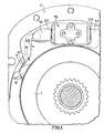
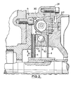
- the brake illustrated in the drawings is of a spreading type in which three rotatable friction discs 1 slidably keyed for axial movement on a rotatable shaft are provided on opposite sides with linings of friction material adapted to be brought into engagement with spaced opposed radial surfaces 2, 3 in a housing 4 by an actuator assembly constituted by a pair of pressure plates 5, 6 located between an adjacent pair of the discs 1 and centred by three angularly spaced stationary pilot lugs of which only one is shown at 7.
- the pilot lugs 7 extend circumferentially for substantially arcuate distances.
- Balls 8 are located in co-operating oppositely inclined recesses 10 in the adjacent faces of the pressure plates 5, 6.
- An intermediate plate 9 is disposed between the friction discs 1 of the pair disposed between the plate 6 and the surface 3.
- the application of the brake is initiated by moving the pressure plates 5, 6 angularly in opposite directions which causes the pressure plates 5, 6 to move axially relatively away from each other due to the tendency for the balls 8 to ride up ramps defined by the end faces of the recesses 10. This urges the friction discs 1 into engagement with the faces 2 and 3 in the housing 4.
- the pressure plates 5, 6 are then carried round with the discs until one is arrested by the engagement of a lug on a respective plate with a drag-taking abutment, as will hereinafter be described, whereafter continued angular movement of the other plate, hereinafter referred to as the "servo plate" provides a servo action.
- the brake is applied mechanically for parking or in an emergency by a pull-rod (not shown) which extends through a radial opening in the housing 4 and is coupled to the outer ends of a pair of toggle links of which the inner ends are pivotally connected to respective pressure plates.
- a pull-rod (not shown) which extends through a radial opening in the housing 4 and is coupled to the outer ends of a pair of toggle links of which the inner ends are pivotally connected to respective pressure plates.
- the brake is applied hydraulically by an hydraulic actuator 15 which acts between actuator lugs 17 and 16 on the respective pressure plates 5, 6.
- the lugs 17 and 16 are displaced angularly from the toggle links.
- the actuator 15 comprises a cylinder 20 having an open-ended longitudinal through-bore 21 in which work a pair of oppositely acting pistons 22, 23 for engagement with the lugs 16 and 17.
- Each piston 22, 23 may work through a seal adjacent to the adjacent outer end of the cylinder 20 and carry a seal adjacent to its inner end.
- a pressure space defined in bore 21 between adjacent inner ends of the pistons 22 and 23 is connected to a master cylinder through a passage 27.
- the housing 4 comprises a casing 30 of bell- shaped outline, and an end plate 31 closing the open end of the casing 30.
- the braking surfaces 2 and 3 are defined by the inner faces of the casing 30 and of the plate 31, respectively.
- Each pressure plate 5, 6 is provided with three angularly spaced pilots, of which only one pilot 40, 41 on each respective plate 5, 6 is shown.
- the three pilots project by substantial distances from the outer edges of the plates 5 and 6.
- the two pilots 40 and 41 extend circumferentially for distances which are relatively small in comparison with the circumferential length of the pilot lug 7 with which they co-operate.
- the pilot 41 and the lug 16 are combined together to comprise a common ear 45 which is integral with the plate 6 and of which the minimum radial dimension is only slightly less than the distance by which the pilot 41 projects from the outer edge of the plate 6.
- the ear 45 enhances the strength of the lug 16 for a given material.
- the two plates 5 and 6 are therefore similar in construction with the pilot 41 of greater length being integral with the actuator lug 16, and the pilot 40 of shorter length being spaced from the pilot 41 by substantially 120°.
- the "servo plate” tends to swing towards the pilot lug 7 with which the shorter pilot 40 co-operates.
- Arranging for the length of the pilot 40 to be short in comparison with the length of the pilot lug 7 reduces the frictional resistance to continued rotation of the "servo plate” to produce the servo on self-energising action.
- the torque taking abutment which arrests the angular movement of one of the pressure plates 5 and 6 is spaced angularly from the other pilot lugs 7 with which the pilots 40 and 41 co-operate, and is located diametrically opposite the hydraulic actuator 15.
- This pilot lug, or torque pin may be positioned at a radius of the brake which is smaller than the radius of the two other pilot lugs.
- the said two other pilot lugs 7 are located at 2 o'clock and 10 o'clock with respect to the torque taking abutment.
Landscapes
- Engineering & Computer Science (AREA)
- General Engineering & Computer Science (AREA)
- Mechanical Engineering (AREA)
- Braking Arrangements (AREA)
Applications Claiming Priority (2)
| Application Number | Priority Date | Filing Date | Title |
|---|---|---|---|
| GB858501221A GB8501221D0 (en) | 1985-01-17 | 1985-01-17 | Self-energising disc brakes |
| GB8501221 | 1985-01-17 |
Publications (2)
| Publication Number | Publication Date |
|---|---|
| EP0189259A2 true EP0189259A2 (de) | 1986-07-30 |
| EP0189259A3 EP0189259A3 (de) | 1987-05-20 |
Family
ID=10573009
Family Applications (1)
| Application Number | Title | Priority Date | Filing Date |
|---|---|---|---|
| EP86300139A Withdrawn EP0189259A3 (de) | 1985-01-17 | 1986-01-10 | Selbsverstärkende Scheibenbremsen |
Country Status (3)
| Country | Link |
|---|---|
| EP (1) | EP0189259A3 (de) |
| GB (1) | GB8501221D0 (de) |
| IN (1) | IN166056B (de) |
Family Cites Families (3)
| Publication number | Priority date | Publication date | Assignee | Title |
|---|---|---|---|---|
| GB1030312A (en) * | 1963-01-11 | 1966-05-18 | Girling Ltd | Improvements in disc brakes |
| US3343632A (en) * | 1965-07-12 | 1967-09-26 | Lambert & Brake Corp | Self-adjusting disc brake |
| GB2031083B (en) * | 1978-09-26 | 1982-08-11 | Lucas Industries Ltd | Spreading disc brakes for vehicles |
-
1985
- 1985-01-17 GB GB858501221A patent/GB8501221D0/en active Pending
-
1986
- 1986-01-10 EP EP86300139A patent/EP0189259A3/de not_active Withdrawn
- 1986-01-16 IN IN23/MAS/86A patent/IN166056B/en unknown
Also Published As
| Publication number | Publication date |
|---|---|
| IN166056B (de) | 1990-03-03 |
| EP0189259A3 (de) | 1987-05-20 |
| GB8501221D0 (en) | 1985-02-20 |
Similar Documents
| Publication | Publication Date | Title |
|---|---|---|
| US4653614A (en) | Self-energizing disc brakes | |
| US5012901A (en) | Self-energizing disc brakes | |
| EP0136434B1 (de) | Scheibenbremse | |
| US6264009B1 (en) | Multi-stage wet disc brake | |
| EP0040027A1 (de) | Scheibenbremsen | |
| US4736820A (en) | Self-energizing disc brakes | |
| US4795003A (en) | Self-energizing disc brakes | |
| US4685541A (en) | Self-energizing disc brakes | |
| US4067417A (en) | Self-energizing applied wedge actuator | |
| EP0209271A2 (de) | Selbstverstärkende Scheibenbremsen | |
| GB2031082A (en) | Spreading disc brakes for vehicles | |
| EP0189259A2 (de) | Selbsverstärkende Scheibenbremsen | |
| US5033591A (en) | Disc brakes for vehicles | |
| US4702351A (en) | Self-energizing disc brakes | |
| US4422533A (en) | Sealing means for hydraulic brake actuators | |
| EP0316070A1 (de) | Selbstverstärkend wirkende Scheibenbremse | |
| EP0192395A1 (de) | Selbstverstärkende Scheibenbremse | |
| EP0188339A2 (de) | Selbstverstärkende Scheibenbremsen | |
| US4768625A (en) | Self-energizing disc brakes | |
| EP0304168A1 (de) | Selbstverstärkend wirkende Scheibenbremse | |
| EP0224341A1 (de) | Selbstverstärkend wirkende Scheibenbremse | |
| US4796730A (en) | Self-energizing disc brakes | |
| EP0265173A2 (de) | Selbstverstärkende Scheibenbremsen | |
| EP0208465A2 (de) | Selbstverstärkende Scheibenbremsen | |
| US4703836A (en) | Self-energising disc brakes with links of different lengths |
Legal Events
| Date | Code | Title | Description |
|---|---|---|---|
| PUAI | Public reference made under article 153(3) epc to a published international application that has entered the european phase |
Free format text: ORIGINAL CODE: 0009012 |
|
| AK | Designated contracting states |
Kind code of ref document: A2 Designated state(s): DE FR GB IT |
|
| PUAL | Search report despatched |
Free format text: ORIGINAL CODE: 0009013 |
|
| AK | Designated contracting states |
Kind code of ref document: A3 Designated state(s): DE FR GB IT |
|
| 17P | Request for examination filed |
Effective date: 19871026 |
|
| 17Q | First examination report despatched |
Effective date: 19880928 |
|
| STAA | Information on the status of an ep patent application or granted ep patent |
Free format text: STATUS: THE APPLICATION IS DEEMED TO BE WITHDRAWN |
|
| 18D | Application deemed to be withdrawn |
Effective date: 19890516 |
|
| RIN1 | Information on inventor provided before grant (corrected) |
Inventor name: PARRY, DAVID Inventor name: PRICE, ANTHONY GEORGE |