EP0189333A2 - Transducteur sismique marin - Google Patents
Transducteur sismique marin Download PDFInfo
- Publication number
- EP0189333A2 EP0189333A2 EP86300535A EP86300535A EP0189333A2 EP 0189333 A2 EP0189333 A2 EP 0189333A2 EP 86300535 A EP86300535 A EP 86300535A EP 86300535 A EP86300535 A EP 86300535A EP 0189333 A2 EP0189333 A2 EP 0189333A2
- Authority
- EP
- European Patent Office
- Prior art keywords
- transducer
- diaphragm
- piston
- transducer according
- marine seismic
- Prior art date
- Legal status (The legal status is an assumption and is not a legal conclusion. Google has not performed a legal analysis and makes no representation as to the accuracy of the status listed.)
- Withdrawn
Links
Images

Classifications
-
- G—PHYSICS
- G01—MEASURING; TESTING
- G01V—GEOPHYSICS; GRAVITATIONAL MEASUREMENTS; DETECTING MASSES OR OBJECTS; TAGS
- G01V1/00—Seismology; Seismic or acoustic prospecting or detecting
- G01V1/02—Generating seismic energy
- G01V1/133—Generating seismic energy using fluidic driving means, e.g. highly pressurised fluids; using implosion
- G01V1/135—Generating seismic energy using fluidic driving means, e.g. highly pressurised fluids; using implosion by deforming or displacing surfaces of enclosures, e.g. by hydraulically driven vibroseis™
Definitions
- This invention relates to a marine seismic transducer for use in generating sound underwater.
- Marine seismic transducers which generate sound by vibration are known but such known transducers have up until now used moving pistons as the active surface area, by which we mean that the moving pistons have acted directly upon the water into which the sound is to be transmitted. It is reported that such transducers can produce excessive pressures due to concentrated flow paths and that the efficiency of the transducers is reduced because of cavitation and swirling.
- U.S. Patent Specification No. 3676840 discloses a marine seismic transducer provided with two signal-radiating hollow shells interconnected by a hydraulic cylinder for causing relative outward movement between the shells, the edges of the shells being connected to each other by means of a flexible hollow torus pressurized to a pressure slightly greater than the external pressure plus the difference in pressures internally and externally of the transducer.
- the torus is not intended to and does not function as the vibration source.
- a marine seismic transducer in which there is provided a vibration source which comprises a flexible sound-transmitting diaphragm which is arranged to act directly upon the water into which the sound is to be transmitted.
- the diaphragm is in the form of a generally cylindrical sleeve, the edges of the sleeve being secured to a body of the transducer.
- a large active surface area can be created.
- the power required to transmit a sound wave through the water is proportional to the square of the active surface area and thus, in the case of a conventional prior art marine transducer, is proportional to ⁇ / 4 X D 2 where D is the diameter of the piston or to 2 x ⁇ / 4 D 2 when two opposed pistons are employed. It will readily be appreciated that by employing a generally cylindrical sleeve of the same diameter and having a length equal to its diameter the active surface is twice that of such opposed pistons.
- the generally cylindrical sleeve construction it becomes possible to streamline the transducer more effectively, which will thus reduce the possibility of cavitation occuring.
- it is a pressure wave rather than a velocity wave which is required to be transmitted through the water, it can be expected that better efficiency will derive from the small but more uniform movement over a large surface area (afforded by the present inventicn) by comparison with a large movement over a small surface area (prior art transducer).
- the flexible diaphragm need not be cylindrical and may, for example, be conical, frusto-conical, toroidal or spheroidal (e.g. spherical or part spherical) in shape.
- a further advantage of the transducer of the present invention is that the pressure within the transducer may be kept above the ambient pressure of the seawater. If the diaphragm is pre- pressurized and a hydraulically operated piston within the transducer is used to cause expansion and contraction of the diaphragm, only one supply is required, the external pressure being used to effect the return stroke of the piston.
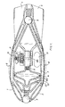
- a marine seismic transducer 1 comprises a streamlined outer casing 2, provided at its front end with a spring-loaded one-way valve 3 and at its rear end with guide fins 4 and a further spring-loaded one-way valve 5.
- a cylinder 7 and a lightweight double piston 8 (formed from e.g. duralumin).
- the double piston 8 comrises two axially arranged pistons 8A and 8B, piston 8A being a high pressure, small surface area piston acted upon by hydraulic fluid and pistcn 8B being a low pressure large surface area piston acting upon seawater within the transducer 1.
- Any suitable circuitry may be employed to reciprocate the piston 8 within the cylinder 7; in the arrangenent shown a hydraulic main valve 9 is employed, operated by hydraulic fluid (e.g. oil or water) supplied from an external source not shown.
- the main valve 9 controls the movement of piston 8A which piston is itself a double sided piston each side being of equal surface area.
- the hydraulic main valve 9 is controlled by an electrically operated pilot valve 10.
- a return line (also not shown) is provided to return the hydraulic fluid to the source.
- the space behind the piston 8 is filled with air at ambient or above ambient pressure (to balance or to pre-pressurize the diaphragm 6 and to act as a cushion for the return stroke of the piston 8) supplied by an air line from a low pressure compressor.
- Accumulators for damping surge during charge and discharge of the cylinder are provided one of which, the discharge accumulator, is shown at 11.
- the accumulators have the effect of smoothing the output at low frequencies and of absorbing excess energy at high pressures.
- Sealing means 14 are provided about the periphery of piston 8B to ensure sealed sliding engagement between cylinder 7 and piston 8B.
- the transducer operates as follows. Water is caused to fill a chamber 12 which communicates with the inner surface of sleeve 6. The working surface 13 of piston 8B is thus able to act upon the water chamber 12.
- main valve 9 acts upon piston 8A to allow hydraulic fluid to advance the piston rapidly (to the left in the drawing) thus causing a pulse of high pressure in the water in chamber 12. This pulse causes the flexible sleeve 6 to expand and to transmit a sound pulse into the water surrounding the transducer 1.
- the return stroke of piston 8 is effected by means of main valve 9 and may be assisted by utilizing ambient pressure and the contraction of sleeve 6.
- Valve 3 can be employed to fill the transducer upon its being lowered in the water, whilst valve 5 acts as an energency relief valve in case of excessive pressures within the transducer. It is envisaged that by suitable selection of spring strengths in valves 3 and 5 the transducer could be rendered self- propelled, the action of piston 8 causing periodic ingress and egress of water respectively through valves 3 and 5.
- FIG. 1 In the alternative embodiment shown in Fig. 2 of the accompanying drawings (in which parts corresponding to those in Fig. 1 are correspondingly designated), a different hydraulic arrangement is employed from that of Fig. 1.
- An electrically operated pilot valve 10 operates a three way hydraulic valve 15.
- This valve 15 supplies high pressure hydraulic fluid to one side only of piston 8A; in other words, the valve 15 is capable of driving piston 8A in one direction only.
- the return stroke of the double piston 8 is effected by the external water pressure, by contraction of the flexible sleeve 6 from its momentarily expanded state and by means of coil spring 16.
- the hydraulic fluid which acts upon piston 8A is discharged via the three way valve 15 either to a return line or, if the hydraulic fluid is seawater, directly into the sea. It will be observed that in addition to the discharge accumulator 11, a charge accumulator 17 is shown as well as air supply line 18 and high pressure seawater supply line 19.
- the transducer of the present invention be capable of operating at frequencies from about 10 Herz up to approximately 200 Hertz and that the frequency be swept up or down during operation.
- the amplitude of the sound transmitted by the transducer of the present invention is satisfactory for use as a siesmic vibration source.
Landscapes
- Engineering & Computer Science (AREA)
- Remote Sensing (AREA)
- Physics & Mathematics (AREA)
- Life Sciences & Earth Sciences (AREA)
- General Physics & Mathematics (AREA)
- Geology (AREA)
- General Life Sciences & Earth Sciences (AREA)
- Acoustics & Sound (AREA)
- Geophysics (AREA)
- Environmental & Geological Engineering (AREA)
- Buildings Adapted To Withstand Abnormal External Influences (AREA)
- Transducers For Ultrasonic Waves (AREA)
- Piezo-Electric Transducers For Audible Bands (AREA)
- Investigating Or Analyzing Materials By The Use Of Ultrasonic Waves (AREA)
- Apparatuses For Generation Of Mechanical Vibrations (AREA)
- Measuring Fluid Pressure (AREA)
- Diaphragms For Electromechanical Transducers (AREA)
- Electrophonic Musical Instruments (AREA)
Applications Claiming Priority (2)
| Application Number | Priority Date | Filing Date | Title |
|---|---|---|---|
| GB858501954A GB8501954D0 (en) | 1985-01-25 | 1985-01-25 | Marine transducer |
| GB8501954 | 1985-01-25 |
Publications (2)
| Publication Number | Publication Date |
|---|---|
| EP0189333A2 true EP0189333A2 (fr) | 1986-07-30 |
| EP0189333A3 EP0189333A3 (fr) | 1986-12-30 |
Family
ID=10573422
Family Applications (2)
| Application Number | Title | Priority Date | Filing Date |
|---|---|---|---|
| EP86300536A Withdrawn EP0190861A3 (fr) | 1985-01-25 | 1986-01-27 | Vibrateur sismique marin |
| EP86300535A Withdrawn EP0189333A3 (fr) | 1985-01-25 | 1986-01-27 | Transducteur sismique marin |
Family Applications Before (1)
| Application Number | Title | Priority Date | Filing Date |
|---|---|---|---|
| EP86300536A Withdrawn EP0190861A3 (fr) | 1985-01-25 | 1986-01-27 | Vibrateur sismique marin |
Country Status (3)
| Country | Link |
|---|---|
| EP (2) | EP0190861A3 (fr) |
| GB (1) | GB8501954D0 (fr) |
| NO (2) | NO860275L (fr) |
Cited By (3)
| Publication number | Priority date | Publication date | Assignee | Title |
|---|---|---|---|---|
| GB2230859A (en) * | 1989-04-21 | 1990-10-31 | British Gas Plc | Seismic pulse generation |
| US5270985A (en) * | 1989-04-21 | 1993-12-14 | British Gas Plc | Seismic pulse generation |
| EP3032283A1 (fr) * | 2014-12-12 | 2016-06-15 | Fugro N.V. | Source sismique tolérante à la pression |
Families Citing this family (1)
| Publication number | Priority date | Publication date | Assignee | Title |
|---|---|---|---|---|
| US9995834B2 (en) * | 2013-05-07 | 2018-06-12 | Pgs Geophysical As | Variable mass load marine vibrator |
Family Cites Families (5)
| Publication number | Priority date | Publication date | Assignee | Title |
|---|---|---|---|---|
| US3376949A (en) * | 1966-12-08 | 1968-04-09 | Texas Instruments Inc | Water hammer marine seismic source |
| US3690403A (en) * | 1970-01-02 | 1972-09-12 | Texas Instruments Inc | Acoustic energy source utilizing the water-hammer phenomenon |
| US3721311A (en) * | 1970-03-11 | 1973-03-20 | Mandrel Industries | Marine seismic source employing the water-hammer effect |
| US3740708A (en) * | 1971-12-27 | 1973-06-19 | Texaco Inc | Seismic pneumatic energy source with bubble eliminator and signal oscillation attenuator |
| US4396088A (en) * | 1981-02-06 | 1983-08-02 | Exxon Production Research Co. | Flexible marine seismic source |
-
1985
- 1985-01-25 GB GB858501954A patent/GB8501954D0/en active Pending
-
1986
- 1986-01-27 NO NO860275A patent/NO860275L/no unknown
- 1986-01-27 NO NO860276A patent/NO860276L/no unknown
- 1986-01-27 EP EP86300536A patent/EP0190861A3/fr not_active Withdrawn
- 1986-01-27 EP EP86300535A patent/EP0189333A3/fr not_active Withdrawn
Cited By (6)
| Publication number | Priority date | Publication date | Assignee | Title |
|---|---|---|---|---|
| GB2230859A (en) * | 1989-04-21 | 1990-10-31 | British Gas Plc | Seismic pulse generation |
| GB2230859B (en) * | 1989-04-21 | 1993-02-10 | British Gas Plc | Seismic pulse generation |
| US5270985A (en) * | 1989-04-21 | 1993-12-14 | British Gas Plc | Seismic pulse generation |
| EP3032283A1 (fr) * | 2014-12-12 | 2016-06-15 | Fugro N.V. | Source sismique tolérante à la pression |
| NL2013968B1 (en) * | 2014-12-12 | 2016-10-11 | Fugro N V | Pressure tolerant seismic source. |
| US10416325B2 (en) | 2014-12-12 | 2019-09-17 | Fugro N.V. | Pressure tolerant seismic source |
Also Published As
| Publication number | Publication date |
|---|---|
| EP0190861A2 (fr) | 1986-08-13 |
| GB8501954D0 (en) | 1985-02-27 |
| NO860276L (no) | 1986-07-28 |
| NO860275L (no) | 1986-07-28 |
| EP0189333A3 (fr) | 1986-12-30 |
| EP0190861A3 (fr) | 1986-12-30 |
Similar Documents
| Publication | Publication Date | Title |
|---|---|---|
| US4578784A (en) | Tunable marine seismic source | |
| US4409681A (en) | Transducer | |
| US6226989B1 (en) | Wave energy converter | |
| US6230840B1 (en) | Marine vibrator | |
| EP1660368B1 (fr) | Systeme de controle de la flottabilite | |
| NO814443L (no) | Marin seismisk energikilde | |
| US3978940A (en) | Acoustic source | |
| US4030063A (en) | Ultra low frequency acoustic generator | |
| JPS6253400B2 (fr) | ||
| GB2107868A (en) | Air release control in seismic energy source air gun | |
| US3205969A (en) | Energy conversion and power amplification system | |
| GB1571790A (en) | Apparatus for extracting powers waves on water | |
| US3554527A (en) | Shock absorber | |
| US3433202A (en) | Impact-energized sound source | |
| CA1155537A (fr) | Canon a air comprime a mecanisme de detente interne | |
| JPH0343596B2 (fr) | ||
| WO1992001875A1 (fr) | Systeme isolant les vibrations pour un support de charge | |
| US3403374A (en) | Underwater hydrodynamic acoustic projector | |
| JPS5871082A (ja) | 流体圧作動媒体と外気との間にシ−ル装置を備える衝撃装置 | |
| CN112530392A (zh) | 一种多模态宽带大功率指向性发射纵振水声换能器 | |
| US5894451A (en) | Impulsive snap-through acoustic pulse generator | |
| US3773008A (en) | Fender device for ships and other boats | |
| NO860275L (no) | Transduser. | |
| AU2003229816A1 (en) | Percussion device with a transmission element compressing an elastic energy storing material | |
| US3246289A (en) | Resonant underwater hydrodynamic acoustic projector |
Legal Events
| Date | Code | Title | Description |
|---|---|---|---|
| PUAI | Public reference made under article 153(3) epc to a published international application that has entered the european phase |
Free format text: ORIGINAL CODE: 0009012 |
|
| AK | Designated contracting states |
Kind code of ref document: A2 Designated state(s): FR GB NL |
|
| PUAL | Search report despatched |
Free format text: ORIGINAL CODE: 0009013 |
|
| AK | Designated contracting states |
Kind code of ref document: A3 Designated state(s): FR GB NL |
|
| 17P | Request for examination filed |
Effective date: 19870209 |
|
| STAA | Information on the status of an ep patent application or granted ep patent |
Free format text: STATUS: THE APPLICATION IS DEEMED TO BE WITHDRAWN |
|
| 18D | Application deemed to be withdrawn |
Effective date: 19880802 |
|
| RIN1 | Information on inventor provided before grant (corrected) |
Inventor name: BREUGELMANS, JACOBUS |