EP0189497A1 - Dispositif pour l'insertion d'au moins un fil de trame dans les métiers à tisser - Google Patents
Dispositif pour l'insertion d'au moins un fil de trame dans les métiers à tisser Download PDFInfo
- Publication number
- EP0189497A1 EP0189497A1 EP85100856A EP85100856A EP0189497A1 EP 0189497 A1 EP0189497 A1 EP 0189497A1 EP 85100856 A EP85100856 A EP 85100856A EP 85100856 A EP85100856 A EP 85100856A EP 0189497 A1 EP0189497 A1 EP 0189497A1
- Authority
- EP
- European Patent Office
- Prior art keywords
- thread
- weft
- weft thread
- tensioning device
- arrangement according
- Prior art date
- Legal status (The legal status is an assumption and is not a legal conclusion. Google has not performed a legal analysis and makes no representation as to the accuracy of the status listed.)
- Granted
Links
- 238000003780 insertion Methods 0.000 title claims abstract description 12
- 230000037431 insertion Effects 0.000 title claims abstract description 12
- 238000009941 weaving Methods 0.000 claims abstract description 8
- 230000033001 locomotion Effects 0.000 claims description 17
- 230000033764 rhythmic process Effects 0.000 claims description 5
- 230000008859 change Effects 0.000 claims description 2
- 238000010304 firing Methods 0.000 description 3
- 230000007246 mechanism Effects 0.000 description 2
- 230000032258 transport Effects 0.000 description 2
- 235000014676 Phragmites communis Nutrition 0.000 description 1
- 230000001133 acceleration Effects 0.000 description 1
- 230000008901 benefit Effects 0.000 description 1
- 238000011161 development Methods 0.000 description 1
- 230000018109 developmental process Effects 0.000 description 1
- 239000004744 fabric Substances 0.000 description 1
- 238000000034 method Methods 0.000 description 1
- 230000008569 process Effects 0.000 description 1
- 230000001360 synchronised effect Effects 0.000 description 1
Images


Classifications
-
- D—TEXTILES; PAPER
- D03—WEAVING
- D03D—WOVEN FABRICS; METHODS OF WEAVING; LOOMS
- D03D47/00—Looms in which bulk supply of weft does not pass through shed, e.g. shuttleless looms, gripper shuttle looms, dummy shuttle looms
- D03D47/34—Handling the weft between bulk storage and weft-inserting means
Definitions
- the invention relates to an arrangement for inserting at least one weft thread for weaving machines, in particular rapier projectile weaving machines, with a first weft thread tensioning device and .. a weft thread transfer device for holding the weft thread until it is transferred to a weft thread insertion device.
- the weft thread builds up in front of the projectile and it can happen that the weft thread end is inclined to the projectile before it is completely closed and is not taken over by the projectile and a so-called loser arises or that the end of the thread gets between the knocking nose of the launcher and the projectile and is squeezed when firing.
- the invention has for its object to provide a weft thread tensioning device of the type defined in the introduction, whereby these disadvantageous phenomena cannot occur.
- This object is achieved according to the invention by the features specified in the characterizing part of claim 1.
- the subclaims relate to advantageous further developments.
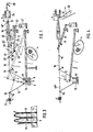
- FIG. 1 shows an arrangement for inserting eight weft threads in alternating operation according to the sample program, which consists of a weft thread tensioning device I and a weft thread tensioning device II.
- the tensioning device I is described below with reference to FIG. 2.
- the tensioning device I has a thread tensioner 1 in the form of a bracket which can be rotated about an axis 2.
- the thread tensioner 1 is guided with a roller 3 on a control disk 4 which is driven by the main shaft of the weaving machine.
- a crossbar 5 of the thread tensioner 1 swings in the machine rhythm across a group 6 of weft threads, each of which originates from a supply spool (not shown).
- the crossbar is provided with eight thread troughs.
- Furthermore, on both sides of the crossbar 5 there is a carrier 11 and 12, each with eight thread eyelets 13 and 14.
- FIG. 3 shows three of the eight holding elements which are fastened on the carrier 8 can hold deflected weft.
- the holding elements fastened on the carrier 9 are designated 19 in FIG. 1.
- the weft thread tensioning device II has eight thread tensioners 25 in the form of a lever with a thread trough 26 which can be rotated about an axis 27. Both on the side of each thread trough there is a thread eyelet 28 and 29 which are fastened on supports 30 and 31 respectively.
- the weft thread family 6 passes through the tensioning device II and a transmitter nozzle 32, the mouth 33 of which ends in the firing position in front of a gripper projectile. Only the thread clamp 34 is drawn from the projectile.
- the transmitter nozzle 32 is fed with compressed air via a line 35.
- each weft thread passes through the eyelet 28, the thread trough 26 in the thread tensioner concerned, the eyelet 29 and one of the eight weft thread guide channels in the donor nozzle 32.
- each thread tensioner 25 is synchronized with the thread tensioner 1 by an associated motor 37 actuated so that the selected thread tensioner 25 is moved up and down between a deflected position 25 ′ and a release position 25 ′′.
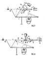
- Fig. 1 The position shown in Fig. 1 is taken as the starting point for the following explanation of the operation of the arrangement. All weft threads are deflected by thread tensioners 1 and 25. The weft threads deflected by the crossbar 5 are held in this position by the holding elements 18 and 19. All weft threads in both tensioning devices I and II are tensioned by pulling the compressed air flowing through the transmitter nozzle 32. The thread clamp 34 is open. When the selected weft thread is inserted - the weft thread 16 is again considered here as an example - the associated thread tensioner 25 initially swings clockwise, so that the weft thread can stretch freely into the position 16 'by the tensile force of the nozzle 32.
- the nozzle 32 blows the end 16 "of the weft thread into the thread clamp 34 of the projectile.
- the weft thread moves forward over a length x. This length is referred to here as the transfer length.
- the thread clamp 34 is now closed. The position is as shown in FIG. 4 shown.
- the thread tensioner 1 of the thread tensioning device I was simultaneously lifted from the control disk 4.
- the thread tensioner 1 has reached the position 1 '.
- the projectile is launched into the shed by a launcher mechanism 38.
- the weft 16 is pulled out of the holding elements 18 and 19.
- the thread brake 17 was opened so that the weft thread with the required entry length is drawn off the supply spool and inserted into the shed.
- the control disk 4 continuously moves the thread tensioner 1 upward, so that the weft thread can stretch freely into the position 16 '"under the influence of the tensile force of the projectile 32.
- the weft threads which are not to be entered remain clamped in their holding elements
- the corresponding thread tensioners of the thread tensioning devices II of the weft threads not to be inserted remain in their deflected position.
- the thread tensioner becomes 1 lowered by the control disk 4 so that the weft thread remains stretched.
- An edge thread clamp on both sides of the shed takes over the weft thread.
- the weft thread is cut through on the weft side by scissors 39 and released on the catch side by the projectile by opening the thread clamp 34.
- the thread is struck by the reed.
- the weft thread is deflected further by the thread tensioner 1, which further lowers and additionally by the thread tensioner 25, which also lowers, until its end lies within the mouth 33 of the nozzle 32. While the thread tensioner 1 with the weft thread to the low moved position, the thread is clamped between the holding elements 18 and 19.
- a transport device picks up the projectile ejected from the trap and transports it back to the launch site outside the shed.
- the projectile is opened by the projectile opener and at the same time swung by a projectile lifter in front of the nozzle 32 so that it is ready to take up the next weft. The position is then again as in FIG. 1.
- FIG. 5 shows an exemplary embodiment, the holding elements 40 and 41 for the weft threads reaching up to the height of the stretched weft threads 42 ′ or even slightly beyond.
- Such long holding elements brake the weft thread practically during its entire insertion movement. Due to the friction experienced by the weft thread, the weft thread is stretched evenly and not jerkily during the entry process, so that it is not excessively stressed.
- the arrangement with a thread tensioner 44 consists of a first tensioning device III with a thread tensioner 44 and a second tensioning device IV.
- the tensioning device IV has a thread tensioner 45 in the form of an egg double lever, which is rotatable about a fixed point 46 and is attached to it free end is provided with a thread eyelet 47 for the weft thread.
- the other end of the thread tensioner 45 is connected to an actuating rod 48 of an actuating motor 49.
- the first tensioning device III and the tensioning device IV thus have the thread eyelets 47 in common.
- the arrangement works in such a way that the transfer of the weft thread 50 to be inserted to the thread clamp of the projectile takes place by a counterclockwise rotation of the thread tensioner 45, so that its part 45 'moves the weft thread from the position 47' to the right by means of the thread eyelet 47 Layer 47 "relocated. There is therefore a partial extension or forward movement of the weft thread, so that the thread length x is released for transfer to the projectile.
- the tensioning devices III and IV are pivoted back into their deflected positions.
- a pivot point 55 of a thread tensioner 56 of a tensioning device V is selected such that the thread eyelet 57 of the thread tensioner lies in a position 57 'below a transmitter nozzle 58 at the end of the release movement of the tensioning device.
- a tensioning device VI for each weft thread has on the one hand three deflecting bodies 65, 66 and 67 below a weft thread 68 and on the other hand two deflecting bodies 69 and 70 which are fastened to an actuating rod 71 of a servomotor 72.
- the deflecting bodies 69 and 70 are located between the deflecting bodies 65, 66 and 66, 67, respectively, so that two loops 73 and 74 are formed and the weft thread end 68 lies in the mouth of a donor nozzle 75.
- the actuating rod 71 is raised from the low position 71 'by the servomotor 72, so that the two loops 73 and 74 stretch and give a total of the transfer lengths x to the projectile.
- both tensioning devices are pivoted back into their deflected position.
- FIG. 9 shows an exemplary embodiment of an arrangement for inserting the weft threads in a two-weft or mixed change operation, with two weft threads being inserted alternately or alternately according to a specific sample program.
- An insertion device is provided for each weft thread 85 or 86.
- the insertion device 87 for the weft thread 85 consists of a tensioning device VII and a tensioning device VIII.
- the insertion device 88 for the weft thread 86 consists of a tensioning device IX and a. Clamping device X. Both entry devices 87 and 88 work alternately or in accordance with the sample program, as previously described for the other embodiments.
- the arrangement can also be rotated by 180, i.e. the thread deflection occurs upwards instead of downwards.
Landscapes
- Engineering & Computer Science (AREA)
- Textile Engineering (AREA)
- Looms (AREA)
Priority Applications (5)
| Application Number | Priority Date | Filing Date | Title |
|---|---|---|---|
| DE8585100856T DE3564596D1 (en) | 1985-01-28 | 1985-01-28 | Arrangement for the insertion of at least one weft thread into looms |
| EP85100856A EP0189497B1 (fr) | 1985-01-28 | 1985-01-28 | Dispositif pour l'insertion d'au moins un fil de trame dans les métiers à tisser |
| US06/817,423 US4649965A (en) | 1985-01-28 | 1986-01-09 | Picking arrangement for a weaving machine |
| SU864007952A SU1454260A3 (ru) | 1985-01-28 | 1986-01-17 | Устройство дл прокладывани по меньшей мере одной уточной нити на бесчелночном ткацком станке преимущественно с микропрокладчиками |
| JP61011231A JPS61174446A (ja) | 1985-01-28 | 1986-01-23 | 織機の緯糸よこ入れ機構 |
Applications Claiming Priority (1)
| Application Number | Priority Date | Filing Date | Title |
|---|---|---|---|
| EP85100856A EP0189497B1 (fr) | 1985-01-28 | 1985-01-28 | Dispositif pour l'insertion d'au moins un fil de trame dans les métiers à tisser |
Publications (2)
| Publication Number | Publication Date |
|---|---|
| EP0189497A1 true EP0189497A1 (fr) | 1986-08-06 |
| EP0189497B1 EP0189497B1 (fr) | 1988-08-24 |
Family
ID=8193260
Family Applications (1)
| Application Number | Title | Priority Date | Filing Date |
|---|---|---|---|
| EP85100856A Expired EP0189497B1 (fr) | 1985-01-28 | 1985-01-28 | Dispositif pour l'insertion d'au moins un fil de trame dans les métiers à tisser |
Country Status (5)
| Country | Link |
|---|---|
| US (1) | US4649965A (fr) |
| EP (1) | EP0189497B1 (fr) |
| JP (1) | JPS61174446A (fr) |
| DE (1) | DE3564596D1 (fr) |
| SU (1) | SU1454260A3 (fr) |
Cited By (1)
| Publication number | Priority date | Publication date | Assignee | Title |
|---|---|---|---|---|
| EP0617153A1 (fr) * | 1993-03-26 | 1994-09-28 | Sulzer RàTi Ag | Procédé pour influencer le mouvement d'un fil de trame tiré d'une bobine de réserve vers le dispositif d'insertion de trame d'un métier à tisser et métier à tisser pour l'exécution de ce procédé |
Families Citing this family (3)
| Publication number | Priority date | Publication date | Assignee | Title |
|---|---|---|---|---|
| BE1003558A3 (nl) * | 1989-09-19 | 1992-04-21 | Picanol Nv | Blaasinrichting voor inslagdraden bij weefmachines. |
| WO2017081711A1 (fr) * | 2015-11-11 | 2017-05-18 | P.T.M.T. S.R.L | Système commandé d'alimentation en fil de trame dans un métier à tisser |
| ITUB20155496A1 (it) * | 2015-11-11 | 2017-05-11 | Pezzoli Miria | Sistema controllato di alimentazione di filo di trama in un telaio |
Citations (5)
| Publication number | Priority date | Publication date | Assignee | Title |
|---|---|---|---|---|
| GB353764A (en) * | 1929-09-23 | 1931-07-30 | Teeag Textil Finanz A G | Improvements in looms with nipping shuttles |
| FR1260351A (fr) * | 1960-06-16 | 1961-05-05 | Sulzer Ag | Dispositif de tension de la matière de trame à insérer dans la foule |
| FR2343066A1 (fr) * | 1976-03-01 | 1977-09-30 | Cheboxarsky Mashstr Zavod | Mecanisme de compensation de la longueur du fil de trame sur un metier a tisser sans navette |
| FR2466548A1 (fr) * | 1979-09-27 | 1981-04-10 | Cretin Louis Atel | Dispositif de retirage de trame apres insertion, pour une machine a tisser avec reserve de trame fixe |
| EP0090878A1 (fr) * | 1982-04-07 | 1983-10-12 | GebràDer Sulzer Aktiengesellschaft | Dispositif de tension de la trame pour métiers à tisser, plus particulièrement pour les métiers à projectiles |
Family Cites Families (1)
| Publication number | Priority date | Publication date | Assignee | Title |
|---|---|---|---|---|
| US2589429A (en) * | 1945-11-24 | 1952-03-18 | Sulzer Ag | Device for tensioning the weft thread in looms |
-
1985
- 1985-01-28 DE DE8585100856T patent/DE3564596D1/de not_active Expired
- 1985-01-28 EP EP85100856A patent/EP0189497B1/fr not_active Expired
-
1986
- 1986-01-09 US US06/817,423 patent/US4649965A/en not_active Expired - Fee Related
- 1986-01-17 SU SU864007952A patent/SU1454260A3/ru active
- 1986-01-23 JP JP61011231A patent/JPS61174446A/ja active Pending
Patent Citations (5)
| Publication number | Priority date | Publication date | Assignee | Title |
|---|---|---|---|---|
| GB353764A (en) * | 1929-09-23 | 1931-07-30 | Teeag Textil Finanz A G | Improvements in looms with nipping shuttles |
| FR1260351A (fr) * | 1960-06-16 | 1961-05-05 | Sulzer Ag | Dispositif de tension de la matière de trame à insérer dans la foule |
| FR2343066A1 (fr) * | 1976-03-01 | 1977-09-30 | Cheboxarsky Mashstr Zavod | Mecanisme de compensation de la longueur du fil de trame sur un metier a tisser sans navette |
| FR2466548A1 (fr) * | 1979-09-27 | 1981-04-10 | Cretin Louis Atel | Dispositif de retirage de trame apres insertion, pour une machine a tisser avec reserve de trame fixe |
| EP0090878A1 (fr) * | 1982-04-07 | 1983-10-12 | GebràDer Sulzer Aktiengesellschaft | Dispositif de tension de la trame pour métiers à tisser, plus particulièrement pour les métiers à projectiles |
Cited By (2)
| Publication number | Priority date | Publication date | Assignee | Title |
|---|---|---|---|---|
| EP0617153A1 (fr) * | 1993-03-26 | 1994-09-28 | Sulzer RàTi Ag | Procédé pour influencer le mouvement d'un fil de trame tiré d'une bobine de réserve vers le dispositif d'insertion de trame d'un métier à tisser et métier à tisser pour l'exécution de ce procédé |
| US5423355A (en) * | 1993-03-26 | 1995-06-13 | Sulzer Rueti Ag | Method and apparatus for limiting stresses in weft yarn advancing towards a weft insertion mechanism |
Also Published As
| Publication number | Publication date |
|---|---|
| JPS61174446A (ja) | 1986-08-06 |
| US4649965A (en) | 1987-03-17 |
| EP0189497B1 (fr) | 1988-08-24 |
| SU1454260A3 (ru) | 1989-01-23 |
| DE3564596D1 (en) | 1988-09-29 |
Similar Documents
| Publication | Publication Date | Title |
|---|---|---|
| DE3781707T2 (de) | Verfahren und vorrichtung zum klemmen, festhalten und vorfuehren von schussfaeden bei greiferwebmaschinen. | |
| CH654601A5 (de) | Schussfadenspannvorrichtung fuer webmaschinen, insbesondere greiferpojektil-webmaschinen. | |
| DE3016192A1 (de) | Elektronischer schussfadenwaechter an einer webmaschine mit greiferschuetzen | |
| EP0189497B1 (fr) | Dispositif pour l'insertion d'au moins un fil de trame dans les métiers à tisser | |
| DE2160998A1 (de) | Vorrichtung zum eintragen von schussfaeden an mit ortsfesten vorratsspulen versehenen webmaschinen | |
| EP0268550B1 (fr) | Tendeur de fils pour machine textile | |
| DE3220064C2 (fr) | ||
| DE2206239C3 (de) | SchuBfadenwechselvorrichtung für Webmaschinen mit Schußfadenführern und ortsfest angeordneten Vorratsspulen | |
| DE2344123A1 (de) | Schuetzenloser webstuhl | |
| DE3812966A1 (de) | Greiferwebmaschine | |
| CH219904A (de) | Schussfadenzubringervorrichtung für einen mit Greifereintragsvorrichtung arbeitenden Webstuhl. | |
| CH646397A5 (de) | Fadenzufuehrvorrichtung zum intermittierenden zufuehren von fadenmaterial unter spannung. | |
| DE2716322A1 (de) | Schuetzenloser webstuhl | |
| DE3124358A1 (de) | "greifer-webmaschine" | |
| CH418249A (de) | Farbenwechselapparat für schützenlose Webmaschinen | |
| DE2707827A1 (de) | Mechanismus zur kompensierung der schussfadenlaenge fuer eine schuetzenlose webmaschine | |
| EP0150231B1 (fr) | Métier à tisser | |
| DE3532638A1 (de) | Greifvorrichtung fuer schuetzenlose webstuehle | |
| DE1815186C (de) | Einrichtung zum Vorlegen und Festhalten eines Schußfadens fur Webmaschinen, bei denen jeder Schußfaden einzeln von einer außerhalb des Webfaches angeordneten Vorratsspule durch Eintragorgane in das Webfach einfuhrbar ist | |
| CH671412A5 (fr) | ||
| DD243304B1 (de) | Vorrichtung zur schussfadenpositionierung an greiferwebmachinen | |
| DE2734598C2 (de) | Verfahren und Vorrichtung zum Bewickeln von Schußfadenträgern einer Wellenfach-Webmaschine | |
| DE1535604C (de) | Schneid und Klemmvorrichtung fur Na delwebmaschinen mit Entnahme des Schußfa dens von orfsfesten Spulen | |
| DE2624141C3 (de) | Verfahren zum Herstellen eines Gewebes auf einer Webmaschine, sowie Vorrichtung zur Durchführung des Verfahrens | |
| DE602425C (de) | Verfahren und Vorrichtung zum Weben mit zwei Kettenfadensystemen |
Legal Events
| Date | Code | Title | Description |
|---|---|---|---|
| PUAI | Public reference made under article 153(3) epc to a published international application that has entered the european phase |
Free format text: ORIGINAL CODE: 0009012 |
|
| AK | Designated contracting states |
Kind code of ref document: A1 Designated state(s): AT BE CH DE FR GB IT LI LU NL SE |
|
| RBV | Designated contracting states (corrected) |
Designated state(s): DE FR IT |
|
| 17P | Request for examination filed |
Effective date: 19861108 |
|
| 17Q | First examination report despatched |
Effective date: 19880129 |
|
| ITF | It: translation for a ep patent filed | ||
| GRAA | (expected) grant |
Free format text: ORIGINAL CODE: 0009210 |
|
| AK | Designated contracting states |
Kind code of ref document: B1 Designated state(s): DE FR IT |
|
| REF | Corresponds to: |
Ref document number: 3564596 Country of ref document: DE Date of ref document: 19880929 |
|
| ET | Fr: translation filed | ||
| PGFP | Annual fee paid to national office [announced via postgrant information from national office to epo] |
Ref country code: FR Payment date: 19890112 Year of fee payment: 5 |
|
| ITTA | It: last paid annual fee | ||
| PGFP | Annual fee paid to national office [announced via postgrant information from national office to epo] |
Ref country code: DE Payment date: 19890228 Year of fee payment: 5 |
|
| PLBE | No opposition filed within time limit |
Free format text: ORIGINAL CODE: 0009261 |
|
| STAA | Information on the status of an ep patent application or granted ep patent |
Free format text: STATUS: NO OPPOSITION FILED WITHIN TIME LIMIT |
|
| 26N | No opposition filed | ||
| PG25 | Lapsed in a contracting state [announced via postgrant information from national office to epo] |
Ref country code: DE Effective date: 19901002 |
|
| PG25 | Lapsed in a contracting state [announced via postgrant information from national office to epo] |
Ref country code: FR Effective date: 19950731 |
|
| REG | Reference to a national code |
Ref country code: FR Ref legal event code: ST |
|
| PG25 | Lapsed in a contracting state [announced via postgrant information from national office to epo] |
Ref country code: FR Effective date: 19900131 |