EP0189560B1 - Zahnradmaschine (Pumpe oder Motor) - Google Patents
Zahnradmaschine (Pumpe oder Motor) Download PDFInfo
- Publication number
- EP0189560B1 EP0189560B1 EP85115455A EP85115455A EP0189560B1 EP 0189560 B1 EP0189560 B1 EP 0189560B1 EP 85115455 A EP85115455 A EP 85115455A EP 85115455 A EP85115455 A EP 85115455A EP 0189560 B1 EP0189560 B1 EP 0189560B1
- Authority
- EP
- European Patent Office
- Prior art keywords
- bushings
- pair
- cavities
- line
- gear machine
- Prior art date
- Legal status (The legal status is an assumption and is not a legal conclusion. Google has not performed a legal analysis and makes no representation as to the accuracy of the status listed.)
- Expired
Links
- 230000003628 erosive effect Effects 0.000 description 3
- 238000007789 sealing Methods 0.000 description 2
- 238000004519 manufacturing process Methods 0.000 description 1
- 239000002245 particle Substances 0.000 description 1
Images
Classifications
-
- F—MECHANICAL ENGINEERING; LIGHTING; HEATING; WEAPONS; BLASTING
- F04—POSITIVE - DISPLACEMENT MACHINES FOR LIQUIDS; PUMPS FOR LIQUIDS OR ELASTIC FLUIDS
- F04C—ROTARY-PISTON, OR OSCILLATING-PISTON, POSITIVE-DISPLACEMENT MACHINES FOR LIQUIDS; ROTARY-PISTON, OR OSCILLATING-PISTON, POSITIVE-DISPLACEMENT PUMPS
- F04C2/00—Rotary-piston machines or pumps
- F04C2/08—Rotary-piston machines or pumps of intermeshing-engagement type, i.e. with engagement of co-operating members similar to that of toothed gearing
- F04C2/082—Details specially related to intermeshing engagement type machines or pumps
- F04C2/086—Carter
Definitions
- the invention relates to a gear machine according to the preamble of the main claim.
- a recess is formed in each socket of a pair of sockets, in such a way that a web remains between two adjacent recesses.
- the recesses extend up to an imaginary straight line that connects the two bushing centers.
- the gear machine according to the invention with the characterizing features of the main claim has the advantage that it is not only easy to manufacture, but that the erosion phenomena mentioned are reduced and thus the efficiency of the machine is improved.
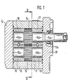
- Figure 1 shows a longitudinal section through a gear pump
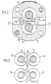
- Figure 2 shows a section along 11-11 of Figure 1
- Figure 3 shows a detail.
- the gear pump has a housing 10 with an interior 11, which is sealed by housing covers 12, 13.
- housing covers 12, 13 In the interior 11 of the housing, two toothed wheels 14, 15 mesh in external engagement, the shaft journals 14a, 14b and 15a, 15b of which are mounted in bearing bushes 16 to 19.
- a through hole 13a is formed in the cover 13, through which the drive shaft 14c of the drive shaft penetrates to the outside.
- each bush has a flat side running in its longitudinal direction, with which flat sides the bushes abut one another.
- the line of engagement E of the gear wheels is also entered in FIG.
- a tapered groove-shaped recess 24 is formed, which is relatively flat, has a connection to the low pressure bore 21 and extends almost to an imaginary straight line G, which connects the two gear shaft centers.
- the recess 24 does not touch the parting line 23.
- a similar recess 25 is formed in the bushing 19, but with the difference that it is obliquely opposite the part 24 with respect to the parting line 23 and is connected to the high-pressure bore 22.
- FIG. 3 shows a top view of the two pairs of bushings, each from the gear side surface.
- the lower pair of sockets 16, 18 is shown tilted by 180 °, so that it can now be understood that the recess 26 is connected to the low-pressure bore, the recess 27 to the high-pressure bore. If you place the two pairs of sockets on top of one another, the recesses 24 to 27 do not lie one above the other, but laterally offset from one another. This idea is facilitated by the engagement lines E shown in FIG. 3.
- the recesses serve to bring pressure medium from grooves 30, 40, which have a triangular cross-section and run in the housing, also from the side to the gearwheels and, in particular, to discharge so-called squeezing oil, ie. H. Oil that forms when the tooth and tooth gap mesh so that excessive pressure is avoided.
- squeezing oil ie. H. Oil that forms when the tooth and tooth gap mesh so that excessive pressure is avoided.
Landscapes
- Engineering & Computer Science (AREA)
- Mechanical Engineering (AREA)
- General Engineering & Computer Science (AREA)
- Rotary Pumps (AREA)
Description
- Die Erfindung geht aus von einer Zahnradmaschine nach der Gattung des Hauptanspruchs. Bei einer derartigen, z. B. aus der DE-A 2510496, bekannten Maschine ist in jeder Buchse eines Buchsenpaares eine Ausnehmung ausgebildet, und zwar derart, daß zwischen zwei benachbarten Ausnehmungen ein Steg stehen bleibt. Die Ausnehmungen erstrecken sich bis nahe an eine gedachte Gerade, welche die beiden Buchsenmitten miteinander verbindet. Es hat sich nun gezeigt, daß bei einer derartigen Ausbildung im Bereich der Eingriffslinie Erosionserscheinungen auftreten, wenn sich Schmutzpartikelchen im Öl befinden, was sehr häufig der Fall ist. Dies führt zu Leckölströmungen und dadurch zu einem verringerten volumetrischen Wirkungsgrad.
- Hierzu ist noch zu bemerken, daß nach der - GB-A-1148651 eine Zahnradpumpe bekannt ist bei welcher auf einer Seite der Zahnräder Dicht platten angeordnet sind. Diese Dichtplatten, und auch auf der anderen Seite die Buchsen haben je nur eine Ausnehmung vermittels welcher die Zahnlücken gefüllt werden. Eine Angabe hinsichtlich ihrer Anordnung in Bezug auf die Eingriffslinie Fehlt aber.
- Die erfindungsgemäße Zahnradmaschine mit den kennzeichnenden Merkmalen des Hauptanspruchs hat demgegenüber den Vorteil, daß sie nicht nur einfach in der Herstellung ist, sondern daß die genannten Erosionserscheinungen verringert werden und damit der Wirkungsgrad der Maschine verbessert wird.
- Ein Ausführungsbeispiel der Erfindung ist in der Zeichnung dargestellt und in der nachfolgenden Beschreibung näher erläutert. Es zeigen Figur 1 einen Längsschnitt durch eine Zahnradpumpe, Figur 2 einen Schnitt längs 11-11 nach Figur 1, Figur 3 eine Einzelheit.
- Die Zahnradpumpe weist ein Gehäuse 10 auf mit einem Innenraum 11 auf, das durch Gehäusedeckel 12, 13 dicht verschlossen ist. Im Innenraum 11 des Gehäuses kämmen zwei Zahnräder 14, 15 im Außeneingriff, deren Wellenzapfen 14a, 14b bzw. 15a, 15b in Lagerbuchsen 16 bis 19 gelagert sind. Im Deckel 13 ist eine Durchgangsbohrung 13a ausgebildet, durch welche der Antriebsschaft 14c der Antriebswelle nach außen dringt.
- In den Innenraum 11 des Gehäuses 10 dringen in Höhe der Zahnräder zwei Bohrungen ein, nämlich eine Niederdruckbohrung 21 und eine Hochdruckbohrung 22. Diese beiden Bohrungen verlaufen achsgleich zueinander. Wie die Figur 2 zeigt, hat jede Buchse eine in ihrer Längsrichtung verlaufende flache Seite, mit welchen Flachseiten die Buchsen aneinanderliegen. Dort ergibt sich eine Trennfuge 23. In Figur 2 ist auch die Eingriffslinie E der Zahnräder eingetragen. An der der Zahnradseitenfläche zugewandten Stirnfläche der Buchse 17 ist eine spitz zulaufende nutförmige Ausnehmung 24 ausgebildet, die verhältnismäßig flach ist, Verbindung zur Niederdruckbohrung 21 hat und sich fast bis zu einer gedachten Geraden G erstreckt, die die beiden Zahnradwellenmitten miteinander verbindet. Die Ausnehmung 24 berührt jedoch nicht die Trennfuge 23-Eine ebensolche Ausnehmung 25 ist in der Buchse 19 ausgebildet, jedoch mit dem Unterschied, daß sie - bezogen auf die Trennfuge 23 - der Ausnehmung 24 schräg gegenüberliegt und mit der Hochdruckbohrung 22 in Verbindung steht.
- Ebensolche Ausnehmungen 26, 27 sind an den Buchsen 16, 18 ausgebildet, jedoch mit dem Unterschied, daß die Ausnehmung 26 mit der Niederdruckbohrung 21 und die Ausnehmung 27 mit der Hochdruckbohrung 22 in Verbindung steht. Die Figur 3 zeigt eine Draufsicht auf die beiden Buchsenpaare jeweils von der Zahnradseitenfläche her. Dabei ist das untere Buchsenpaar 16, 18 um 180° gekippt dargestellt, so daß nun zu verstehen ist, daß die Ausnehmung 26 mit der Niederdruckbohrung, die Ausnehmung 27 mit der Hochdruckbohrung in Verbindung steht. Wenn man also die beiden Buchsenpaare aufeinanderlegt, so liegen die Ausnehmungen 24 bis 27 nicht übereinander, sondern seitlich versetzt zueinander. Erleichtert wird diese Vorstellung durch die in Figur 3 eingezeichneten Eingriffslinien E.
- Die Ausnehmungen dienen dazu, Druckmittel aus Nuten 30, 40, welche dreieckförmigen Querschnitt haben und im Gehäuse verlaufen, auch von der Seite her an die Zahnräder heranzubringen und vor allem sogenanntes Quetschöl abzuführen, d. h. Öl, das sich beim Ineinandergreifen von Zahn und Zahnlücke bildet, so daß Drucküberhöhungen vermieden werden.
Claims (2)
Applications Claiming Priority (2)
| Application Number | Priority Date | Filing Date | Title |
|---|---|---|---|
| DE19853500673 DE3500673A1 (de) | 1985-01-11 | 1985-01-11 | Zahnradmaschine (pumpe oder motor) |
| DE3500673 | 1985-01-11 |
Publications (2)
| Publication Number | Publication Date |
|---|---|
| EP0189560A1 EP0189560A1 (de) | 1986-08-06 |
| EP0189560B1 true EP0189560B1 (de) | 1989-04-26 |
Family
ID=6259585
Family Applications (1)
| Application Number | Title | Priority Date | Filing Date |
|---|---|---|---|
| EP85115455A Expired EP0189560B1 (de) | 1985-01-11 | 1985-12-05 | Zahnradmaschine (Pumpe oder Motor) |
Country Status (2)
| Country | Link |
|---|---|
| EP (1) | EP0189560B1 (de) |
| DE (2) | DE3500673A1 (de) |
Families Citing this family (3)
| Publication number | Priority date | Publication date | Assignee | Title |
|---|---|---|---|---|
| DE19915784C2 (de) * | 1999-04-08 | 2001-03-01 | Fresenius Medical Care De Gmbh | Zahnradpumpe, insbesondere für medizinische Zwecke |
| DE102017112699A1 (de) * | 2017-06-08 | 2018-12-13 | Schwäbische Hüttenwerke Automotive GmbH | Außenzahnradpumpe |
| US11060559B2 (en) * | 2018-06-11 | 2021-07-13 | Eaton Intelligent Power Limited | Bi-metallic journal bearing with additive manufactured sleeve |
Family Cites Families (4)
| Publication number | Priority date | Publication date | Assignee | Title |
|---|---|---|---|---|
| DE366152C (de) * | 1922-12-30 | Bbc Brown Boveri & Cie | Einrichtung zur Vermeidung der Quetschwirkung bei Zahnrad-OElpumpen | |
| US2865302A (en) * | 1955-05-18 | 1958-12-23 | Thompson Prod Inc | Pressure-loaded gear pump |
| GB1148651A (en) * | 1965-04-24 | 1969-04-16 | Armstrong Patents Co Ltd | Improvements in and relating to gear pumps |
| DE2510496C3 (de) * | 1975-03-11 | 1978-07-20 | Robert Bosch Gmbh, 7000 Stuttgart | Zahnradmaschine (Pumpe oder Motor) |
-
1985
- 1985-01-11 DE DE19853500673 patent/DE3500673A1/de not_active Withdrawn
- 1985-12-05 DE DE8585115455T patent/DE3569788D1/de not_active Expired
- 1985-12-05 EP EP85115455A patent/EP0189560B1/de not_active Expired
Also Published As
| Publication number | Publication date |
|---|---|
| EP0189560A1 (de) | 1986-08-06 |
| DE3500673A1 (de) | 1986-07-17 |
| DE3569788D1 (en) | 1989-06-01 |
Similar Documents
| Publication | Publication Date | Title |
|---|---|---|
| DE1906057C3 (de) | Rotationskolbenmaschine mit Schraubenrotor und Dichtungszahnrad | |
| DE3400594A1 (de) | Stroemungsmaschine | |
| EP0093917B1 (de) | Reversierbare Zahnradmaschine (Pumpe oder Motor) | |
| DE2411492A1 (de) | Zahnradpumpe | |
| DE2303413A1 (de) | Zahnrad-kraftmaschine | |
| DE102004021216B4 (de) | Hochdruck-Innenzahnradmaschine mit mehrfacher hydrostatischer Lagerung pro Hohlrad | |
| EP0754859A2 (de) | Zahnrad mit Bohrung | |
| EP0189560B1 (de) | Zahnradmaschine (Pumpe oder Motor) | |
| DE3048984A1 (de) | Rotationslaufradpumpe oder -motor | |
| DE1264958B (de) | Zahnradpumpe oder -motor | |
| DE1653810C3 (de) | Zahnradpumpe | |
| DE4338875C2 (de) | Reversierbare Innenzahnradmaschine (Pumpe oder Motor) | |
| DE4124466C2 (de) | Zahnradmaschine (Pumpe oder Motor) | |
| DE3605246C2 (de) | Zahnradmaschine (Pumpe oder Motor) | |
| DE4217160C2 (de) | Zahnradmaschine (Pumpe oder Motor) | |
| DE2414760A1 (de) | Zahnradpumpe | |
| DE2701303C3 (de) | Hydraulische Zahnradmaschine | |
| DE2443600A1 (de) | Zahnradmaschine | |
| DE3701099A1 (de) | Zahnradmaschine (pumpe oder motor) | |
| EP0291722B1 (de) | Zahnradmaschine (Pumpe oder Motor) | |
| DE4345269C2 (de) | Innenzahnradmaschine (Pumpe oder Motor) | |
| EP0614011B1 (de) | Zahnradmaschine (Pumpe oder Motor) | |
| DE7500496U (de) | Ahnradmaschine (pumpe oder motor) | |
| EP0062747B1 (de) | Hydraulischer Zahnradmotor | |
| DE19746769C1 (de) | Sichellose Innenzahnradmaschine |
Legal Events
| Date | Code | Title | Description |
|---|---|---|---|
| PUAI | Public reference made under article 153(3) epc to a published international application that has entered the european phase |
Free format text: ORIGINAL CODE: 0009012 |
|
| AK | Designated contracting states |
Kind code of ref document: A1 Designated state(s): DE FR GB IT |
|
| 17P | Request for examination filed |
Effective date: 19860904 |
|
| 17Q | First examination report despatched |
Effective date: 19871126 |
|
| GRAA | (expected) grant |
Free format text: ORIGINAL CODE: 0009210 |
|
| AK | Designated contracting states |
Kind code of ref document: B1 Designated state(s): DE FR GB IT |
|
| GBT | Gb: translation of ep patent filed (gb section 77(6)(a)/1977) | ||
| REF | Corresponds to: |
Ref document number: 3569788 Country of ref document: DE Date of ref document: 19890601 |
|
| ET | Fr: translation filed | ||
| ITF | It: translation for a ep patent filed | ||
| PLBE | No opposition filed within time limit |
Free format text: ORIGINAL CODE: 0009261 |
|
| STAA | Information on the status of an ep patent application or granted ep patent |
Free format text: STATUS: NO OPPOSITION FILED WITHIN TIME LIMIT |
|
| 26N | No opposition filed | ||
| ITTA | It: last paid annual fee | ||
| PGFP | Annual fee paid to national office [announced via postgrant information from national office to epo] |
Ref country code: GB Payment date: 19931125 Year of fee payment: 9 |
|
| PGFP | Annual fee paid to national office [announced via postgrant information from national office to epo] |
Ref country code: FR Payment date: 19931230 Year of fee payment: 9 |
|
| PG25 | Lapsed in a contracting state [announced via postgrant information from national office to epo] |
Ref country code: GB Effective date: 19941205 |
|
| GBPC | Gb: european patent ceased through non-payment of renewal fee |
Effective date: 19941205 |
|
| PG25 | Lapsed in a contracting state [announced via postgrant information from national office to epo] |
Ref country code: FR Effective date: 19950831 |
|
| REG | Reference to a national code |
Ref country code: FR Ref legal event code: ST |
|
| PGFP | Annual fee paid to national office [announced via postgrant information from national office to epo] |
Ref country code: DE Payment date: 19960222 Year of fee payment: 11 |
|
| PG25 | Lapsed in a contracting state [announced via postgrant information from national office to epo] |
Ref country code: DE Effective date: 19970902 |