EP0189566A2 - Installation de commutation avec un dispositif de limitation de courant et de court-circuit prévu dans l'alimentation - Google Patents
Installation de commutation avec un dispositif de limitation de courant et de court-circuit prévu dans l'alimentation Download PDFInfo
- Publication number
- EP0189566A2 EP0189566A2 EP85115689A EP85115689A EP0189566A2 EP 0189566 A2 EP0189566 A2 EP 0189566A2 EP 85115689 A EP85115689 A EP 85115689A EP 85115689 A EP85115689 A EP 85115689A EP 0189566 A2 EP0189566 A2 EP 0189566A2
- Authority
- EP
- European Patent Office
- Prior art keywords
- short
- current
- circuit
- switch
- current limiting
- Prior art date
- Legal status (The legal status is an assumption and is not a legal conclusion. Google has not performed a legal analysis and makes no representation as to the accuracy of the status listed.)
- Withdrawn
Links
Images

Classifications
-
- H—ELECTRICITY
- H02—GENERATION; CONVERSION OR DISTRIBUTION OF ELECTRIC POWER
- H02B—BOARDS, SUBSTATIONS OR SWITCHING ARRANGEMENTS FOR THE SUPPLY OR DISTRIBUTION OF ELECTRIC POWER
- H02B1/00—Frameworks, boards, panels, desks, casings; Details of substations or switching arrangements
- H02B1/24—Circuit arrangements for boards or switchyards
Definitions
- the invention relates to a switchgear assembly with a central current limiting and short-circuiting device provided in the feed, a superfast short-circuiting device and a circuit breaker, and with feeder switches provided in the outgoers, the busbar sections being coupled via a tie switch in the case of multiple feeds.
- Switchgear for the distribution of electrical energy in industrial and public networks is required, inter alia, to ensure a high level of supply reliability and safe operation.
- a fully insulated high-voltage switchgear is known from DE-AS 1 690 739, 21 c, 42/03, in which the effort required for the switches is to be reduced.
- the busbar of this high-voltage switchgear is fed via a circuit breaker, and the switches via which the outlets are connected to the busbar are fast-switching isolating switches that can be switched off during a currentless pause by locking against the circuit breaker, which can be opened by briefly opening the circuit breaker is generated by means of a storage drive for short interruption.
- Switchgear can be simplified due to the use of fast-switching disconnectors instead of load-break switches, but it has the disadvantage that there are brief interruptions in the outgoers in which no operating or interference currents can be switched when operating circuits are required. For numerous consumers, such as B.. Such short interruptions are not acceptable for fluorescent lamps and process computers.
- the invention seeks to remedy this.
- the invention solves the problem of creating a switchgear in which the current limiting and short-circuiting device provided in the feed and the feeder switches provided in the outlets as well as the superfast short-circuiter in the feed thus influence
- short-circuit currents, inrush and starting currents as well as fault currents, which have a fixed multiple value of the nominal current of the respective outgoing circuit have switch
- fault currents that are smaller than the specified multiple of the nominal current of the respective feeder and arcing faults can be safely controlled by the fact that each central current limiting and short-circuit device provided in an infeed, which has a reduced sensitivity for inrush and starting currents , a logic operation of automatic matching is carried out, which on the one hand is connected via an information line and a logic module assigned to each outlet with the current detection as a component of the fault current sensor also assigned to each outlet, in such a way that in the case of fault currents that
- the outgoing switch that switches off these fault currents can be controlled directly by the current detector as part of the fault current sensor via the logic module to switch off the fault current.
- a circuit breaker or a circuit breaker can be provided instead of the circuit breaker located in the respective infeed, while the outgoers and tie switches are advantageously circuit breakers.
- the current limiting and short-circuiting device In order to reduce the threshold value for the response of the current limiting and short-circuiting device, in a further embodiment of the invention it is provided with fixed short-circuit windings which can be switched off.
- the current limiting and short-circuiting device has, in addition to a stationary coil lying in the current path of the infeed, a movable short-circuit cylinder which can be influenced by the current flowing through this coil and which is firmly connected to a contact rod which is operatively connected to a fixed earth contact, with the threshold value for being reduced the response of the current limiting and short-circuit device, the threshold value for the start of the movement of the short-circuit cylinder can be reduced.
- the current limiting and short-circuiting device is designed without a short-circuiting part and the automatic coupling first enables the coupling switch and then the outgoing switch of the faulty outlet to be triggered. Regardless of how now.
- the short-circuiting part of the current limiting and short-circuiting device can therefore be dispensed with in this configuration of the switching devices used.
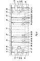
- the operating current flows through the circuit breaker 3, the fixed coil 8, the commutation contact 6 and via the contact rod 7 to the busbar 4.
- the principle of the current limiting and short-circuiting device 1; 2 is based on the fact that, in the event of a fault, an electrodynamic drive system fed by the fault current, consisting of the fixed coil 8 and the movable short-circuit cylinder 10, switches on the limiting impedance 5 in such a way that the contact rod 7 rigidly connected to the short-circuit cylinder 10 opens the commutation contact 6 and the current now flows via the circuit breaker 3, the fixed coil 8 and via the limiting impedance to the busbar 4.
- the movement of the movable short-circuit cylinder 10 continues until, after a switching path, the contact rod 7 has ground Contact 12 comes into contact and, when the switching device 13 is closed, the busbar 4 is grounded. If the earth contact 12 is present and the switching device 13 is closed, the current limiting and short-circuiting device 1 operates; 2 as current limiters and short-circuiters; however, if the earth contact 12 is not present or the switching device 13 is open, the current limiting and short-circuiting device 1 operates; 2 only as a current limiter.
- the automatic adaptation 37 of the current limiting .. and short-circuiting device has on the one hand the task of increasing the sensitivity of the response of the short-circuit cylinder 10 in the event of low-current faults and, on the other hand, reducing the sensitivity to inrush and starting currents.
- the switchgear assembly 14 is provided in addition to the current limiting and short-circuiting device 1; Equipped with super fast short closers 38 2, so that here too via the fast Störlichtbogenerkennung as part of the leak sensor 39, a logic device 40 and a 'Informationa réelle 41, a logical operation performing any current limiting and short-circuit device 1; 2 assigned automatic adaptation 37 receives the information required for the logical linkage, so that the current path of the superfast short-circuiter 38 after the reaction time of the current limiting and short-circuiting device 1; 2 is relieved and the circuit breaker 3 switches off the arcing fault.
- the tie switch 17 can operate the current limiting and short-circuit device 1; 2 as a current limiter and short-circuiter at the same time as the relevant outgoing switch 24; 25; 26; 27 of the corresponding faulty outlet 20; 21; 22; 23 are opened and thus one of the busbar sections 18; 19 are supplied again.
Landscapes
- Engineering & Computer Science (AREA)
- Power Engineering (AREA)
- Emergency Protection Circuit Devices (AREA)
Applications Claiming Priority (2)
| Application Number | Priority Date | Filing Date | Title |
|---|---|---|---|
| DD271877 | 1984-12-28 | ||
| DD27187784A DD233251A1 (de) | 1984-12-28 | 1984-12-28 | Verfahren zum betrieb von elektroenergieanlagen mit einer zentralen strombegrenzungs- und kurzschliessereinrichtung |
Publications (2)
| Publication Number | Publication Date |
|---|---|
| EP0189566A2 true EP0189566A2 (fr) | 1986-08-06 |
| EP0189566A3 EP0189566A3 (fr) | 1988-05-04 |
Family
ID=5564235
Family Applications (1)
| Application Number | Title | Priority Date | Filing Date |
|---|---|---|---|
| EP85115689A Withdrawn EP0189566A3 (fr) | 1984-12-28 | 1985-12-10 | Installation de commutation avec un dispositif de limitation de courant et de court-circuit prévu dans l'alimentation |
Country Status (2)
| Country | Link |
|---|---|
| EP (1) | EP0189566A3 (fr) |
| DD (1) | DD233251A1 (fr) |
Cited By (1)
| Publication number | Priority date | Publication date | Assignee | Title |
|---|---|---|---|---|
| DE102009031647A1 (de) * | 2009-07-03 | 2011-01-05 | Moeller Gmbh | Strombegrenzungsvorrichtung |
Family Cites Families (3)
| Publication number | Priority date | Publication date | Assignee | Title |
|---|---|---|---|---|
| DE1440894A1 (de) * | 1962-12-13 | 1969-03-20 | Concordia Sprecher Schalt | Elektrischer Schalter |
| DE1690739B1 (de) * | 1965-08-27 | 1970-06-18 | Siemens Ag | Vollisolierte Hochspannungsschaltanlage |
| DE2157103A1 (de) * | 1971-11-12 | 1973-05-17 | Siemens Ag | Vollisolierte hochspannungsschaltanlage |
-
1984
- 1984-12-28 DD DD27187784A patent/DD233251A1/de not_active IP Right Cessation
-
1985
- 1985-12-10 EP EP85115689A patent/EP0189566A3/fr not_active Withdrawn
Cited By (1)
| Publication number | Priority date | Publication date | Assignee | Title |
|---|---|---|---|---|
| DE102009031647A1 (de) * | 2009-07-03 | 2011-01-05 | Moeller Gmbh | Strombegrenzungsvorrichtung |
Also Published As
| Publication number | Publication date |
|---|---|
| DD233251A1 (de) | 1986-02-19 |
| EP0189566A3 (fr) | 1988-05-04 |
Similar Documents
| Publication | Publication Date | Title |
|---|---|---|
| DE69216179T2 (de) | Elektrisches Leistungsversorgungssystem | |
| DE19601540C2 (de) | Elektrisches Verteilungssystem | |
| EP3091550B1 (fr) | Dispositif de commutation hybride | |
| EP3510618B1 (fr) | Disjoncteur | |
| EP3639353B1 (fr) | Impédance pour controler des courants de défaut dans un convertisseur c.c.h.t. | |
| EP3635851B1 (fr) | Unité de convertisseur de courant | |
| EP0247289A1 (fr) | Contrôle d'erreur d'une dérivation de transformateur moyenne tension | |
| DE1965504C3 (de) | Metallumschlossene elektrische Trennvorrichtung für hohe Spannung | |
| DE69213082T2 (de) | Gasisolierter Trennschalter und Schaltvorrichtung | |
| DE69122078T2 (de) | Leistungseinführungssystem | |
| DE2208432A1 (de) | Leistungsschalter für Hochspannungssysteme | |
| EP0261606A2 (fr) | Circuit de protection | |
| DE2712232A1 (de) | Verfahren zur ausserbetriebnahme eines pols einer hgue-station | |
| DE2817207C2 (fr) | ||
| DE3784682T2 (de) | Wechselstromleistungsschaltkreis und sicherung dafuer. | |
| DE4108049C2 (de) | Schutzsystem für Nieder-, Mittel- oder Hochspannungsnetze mit hierarchisch gegliederten Netzebenen | |
| DE3709664C2 (fr) | ||
| CH675321A5 (en) | Heavy current switch with anti-magnetic encapsulation | |
| DD215427A1 (de) | Schaltanlage zur verteilung von elektroenergie sowie verfahren zum betreiben der schaltanlage | |
| EP3437169A1 (fr) | Agencement de circuits à fonction de déconnexion à minimum ou maximum de tension pour la protection de consommateurs, raccordés à un réseau polyphasés | |
| EP0504463B1 (fr) | Circuit pour alimentation en courant | |
| EP4213175B1 (fr) | Disjoncteur basse tension avec circuit imprime et prise de tension et procédé de montage | |
| DE102022118372B4 (de) | Anordnung zum Unterbrechen von Strom in einer Hochspannungsleitung und Verfahren zum Betreiben einer solchen Anordnung | |
| LU505555B1 (de) | Trennschalter | |
| DD233251A1 (de) | Verfahren zum betrieb von elektroenergieanlagen mit einer zentralen strombegrenzungs- und kurzschliessereinrichtung |
Legal Events
| Date | Code | Title | Description |
|---|---|---|---|
| PUAI | Public reference made under article 153(3) epc to a published international application that has entered the european phase |
Free format text: ORIGINAL CODE: 0009012 |
|
| AK | Designated contracting states |
Kind code of ref document: A2 Designated state(s): AT BE DE FR GB IT NL SE |
|
| RAP1 | Party data changed (applicant data changed or rights of an application transferred) |
Owner name: VEB ELEKTROPROJEKT UND ANLAGENBAU BERLIN |
|
| PUAL | Search report despatched |
Free format text: ORIGINAL CODE: 0009013 |
|
| AK | Designated contracting states |
Kind code of ref document: A3 Designated state(s): AT BE DE FR GB IT NL SE |
|
| 17P | Request for examination filed |
Effective date: 19880506 |
|
| 18W | Application withdrawn |
Withdrawal date: 19880722 |
|
| STAA | Information on the status of an ep patent application or granted ep patent |
Free format text: STATUS: THE APPLICATION HAS BEEN WITHDRAWN |
|
| R18W | Application withdrawn (corrected) |
Effective date: 19880722 |
|
| RIN1 | Information on inventor provided before grant (corrected) |
Inventor name: MISCHNICK, ULRICH, DIPL.-ING. Inventor name: GERLACH, HORST, DR.-ING. |