EP0189582A2 - Dispositif pour saisir et détacher le début d'une bobine - Google Patents
Dispositif pour saisir et détacher le début d'une bobine Download PDFInfo
- Publication number
- EP0189582A2 EP0189582A2 EP85116342A EP85116342A EP0189582A2 EP 0189582 A2 EP0189582 A2 EP 0189582A2 EP 85116342 A EP85116342 A EP 85116342A EP 85116342 A EP85116342 A EP 85116342A EP 0189582 A2 EP0189582 A2 EP 0189582A2
- Authority
- EP
- European Patent Office
- Prior art keywords
- web
- gripper
- bobbin
- roller
- leg
- Prior art date
- Legal status (The legal status is an assumption and is not a legal conclusion. Google has not performed a legal analysis and makes no representation as to the accuracy of the status listed.)
- Granted
Links
Images


Classifications
-
- B—PERFORMING OPERATIONS; TRANSPORTING
- B65—CONVEYING; PACKING; STORING; HANDLING THIN OR FILAMENTARY MATERIAL
- B65H—HANDLING THIN OR FILAMENTARY MATERIAL, e.g. SHEETS, WEBS, CABLES
- B65H19/00—Changing the web roll
- B65H19/10—Changing the web roll in unwinding mechanisms or in connection with unwinding operations
- B65H19/105—Opening of web rolls; Removing damaged outer layers; Detecting the leading end of a closed web roll
-
- B—PERFORMING OPERATIONS; TRANSPORTING
- B65—CONVEYING; PACKING; STORING; HANDLING THIN OR FILAMENTARY MATERIAL
- B65H—HANDLING THIN OR FILAMENTARY MATERIAL, e.g. SHEETS, WEBS, CABLES
- B65H16/00—Unwinding, paying-out webs
Definitions
- the invention relates to a device for detecting the start of a web of paper, textile, plastic and / or metal foil wound on a core into a bobbin for the purpose of further processing on a downstream machine, preferably a packaging machine.
- the invention has for its object to provide a device for detecting and releasing the beginning of a web wound on a core into a bobbin for further processing on a downstream machine, which preferably prepares automatically delivered bobbins for further processing without manual activities.
- the solution to this problem by the invention is characterized in that at least two rollers are rotatably mounted on a support plate, one roller of which is driven by a motor, that a gripper-like gripper is provided which detects the beginning of the web defined on the bobbin for the purpose of securing the transportation can be adjusted resiliently against the circumference of the bobbin and one leg of which is designed as a scraper for driving under the beginning of the web or an adhesive strip defining the beginning of the web and the other leg for controlling the beginning of the web or the adhesive strip can be pressed in a controlled manner against the leg designed as a scraper, and that the gripper is movably supported by an approximately tangential movement relative to the bobbin and the detected path start at the same timely rotation of the bobbin on the rollers feeds a cutting device, the cutting edge of which detects the detected beginning of the path and which holds the new beginning of the path thus created until it is taken over by a transport device.
- the bobbin feed, the changing of the bobbins and the threading of the respective start of the path can take place automatically and without manual intervention, so that not only is the loading of heavy bobbins by hand, but also the cumbersome threading is eliminated.
- the device according to the invention has a simple structure and high functional reliability, so that it can also be used reliably in modern high-performance machines. It is suitable for processing a wide variety of web materials and web dimensions without the basic structure having to be changed.
- the support plate with the rollers and the motor can be pivoted between a horizontal receiving position and a vertical working position. This simplifies the feeding of the bobbins to the device according to the invention, since they can be applied from above to the support plate located in the horizontal receiving position.
- three rollers are arranged on the support plate, of which one roller is adjustably mounted on the support plate for pressing against the circumference of the respective bobbin.
- the adjustable roller can, according to the invention, be rotatably mounted on a swivel arm which can be swiveled between a receiving position and a working position by means of a pressure medium cylinder.
- the bobbin to be processed is placed on the support plate when the roller is pivoted into the receiving position and then aligned by moving the swivel arm into the working position before the supporting plate is pivoted into the vertical working position, for example by means of a pressure medium cylinder.
- the motor driving the roller by means of a marking recognizing the beginning of the web when the bobbin held between the rollers rotates Sensor controlled.
- the marking can also be attached to the circumference of the bobbin or formed by the adhesive strip to determine the start of the path.
- the gripper with its leg designed as a scraper can be lifted against a stop against spring force for tangential contact with the circumference of the bobbin. This ensures that the gripper rests reliably on the circumference of the bobbin during its gripping movement.
- the gripper is preferably arranged on a support arm movable by a pressure medium cylinder.
- this support arm is pivotally mounted at one end and on the other end with a bearing pin for pivotable mounting of the gripper and with the stop for the gripper.
- the movable leg of the gripper can be designed either as a rigid component which can be pivoted about a pivot point by means of a pressure medium cylinder or as a drivable take-off roller.
- a predeterminable length of the bobbin web can be drawn off before the cutting process by driving this take-off roller, for example a length corresponding to a complete bobbin circumference, whereby dirt or damage to the web are removed.
- a predeterminable length of the web can be cut off, which is greater than the length of the pulling-off movement of the gripper if, according to a further feature of the invention, the gripper can be transferred into an end position lying below the cutting device, in which detects the start of the web by a pair of driven transport rollers and is pulled off by a predetermined length after opening the gripper.
- the cutting device of the device according to the invention is preferably equipped with a pair of jaws which can be pressed resiliently against one another for holding the web separated by the cutting edge in order to hold the newly created beginning of the web until it has been taken over by corresponding components of the downstream transport device.
- This transport device can be part of the downstream packaging machine or part of an additional device with which the opened bobbin the further processing carried out at a remote location.
- the invention proposes to assign to the gripper two suction cups that can be placed on the surface of the web next to the centrally defined start of the web to lift the outer corners of the beginning of the web before being gripped by the gripper.
- These suction cups which are controlled in accordance with the movement of the gripper, have the effect that, on the one hand, the leg of the gripper, designed as a scraper, reliably engages under the defined path start and, on the other hand, this path start is reliably grasped by the movable leg.
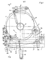
- a support plate 3 can be pivoted between a horizontal receiving position and a vertical working position by means of a bearing axis 2.
- the working position of the support plate 3 is shown in Figures 1 and 2 with solid lines.
- the horizontal recording position is indicated in Fig.2 with dash-dotted lines.
- Figures 1 and 2 also show a pressure medium cylinder 4 arranged on the base frame 1, the piston rod 4a of which is connected to the support plate 3 via a lever 4b fastened to the bearing axis 2.
- the piston rod 4a holds the support plate 3 in the working position drawn in solid lines in FIG. 2;
- the support plate 3 In the retracted position of the piston rod 4a, the support plate 3 is pivoted into the horizontal receiving position, which is shown in dash-dot lines in FIG.
- rollers 5a, 5b and 5c are rotatably mounted on the support plate 3. While the rollers 5a and 5b are fixedly arranged on the support plate 3, the roller 5c is located at the pivotable end of a swivel arm 6 which can be actuated by a pressure medium cylinder 7. Through this pressure medium cylinder 7, the swivel arm 6 with the Roller 5c can be pivoted from a pick-up position shown in broken lines in FIG. 1 into a working position drawn with solid lines.
- the rollers 5a, 5b and 5c serve to hold and store a bobbin B, which is placed from above onto the support plate 3 located in the horizontal receiving position.
- the bobbin can, for example, assume the position indicated by dash-dotted lines in FIG.
- the roller 5c is pressed against the circumference of the bobbin B, which in this way is moved by the force of the pressure medium cylinder 7 into the final position shown in solid lines in FIG. 1, in which it is on the rollers 5a and 5b is present. Only after this alignment, the support plate 3 is pivoted into the vertical working position with the aid of the pressure medium cylinder 4.
- the core K used to transport the bobbin B, on which the web of the bobbin B is wound, can be seen in FIG.
- the roller 5b can be driven by a motor 8 which is flanged to the rear of the support plate 3.
- a motor 8 which is flanged to the rear of the support plate 3.
- the roller 5b By the drive of the roller 5b indicated by arrows in FIG. 1, the bobbin B resting on the rollers 5a and 5b is rotated in the direction of the arrow until a sensor 9 detects the start of the web A.
- This detection can be done by additional markings on the circumference of the bobbin.
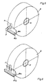
- a self-adhesive strip S can also serve as a marking according to FIG. 3, by means of which the beginning of the web A is fixed to the position of the reel B located underneath.
- a gripper 10 of which a first exemplary embodiment is shown in FIGS. 1 to 4, is used to release the start of the path A.
- This gripper 10 comprises a leg designed as a scraper 10a for tangential contact with the circumference of the bobbin B and a movable leg 10b which can be pressed by a pressure medium cylinder 10c onto the leg designed as a scraper 10a as soon as it detects the beginning of the web A or the self-adhesive strip S. Has.
- the gripper 10 is moved by an approximately tangential movement relative to the bobbin B, which is thereby rotated at the same time.
- the gripper 10 is pivotally mounted on the front end of a support arm 11, which in turn is pivoted on a bearing pin 11a on the base frame 1.
- the pivoting of the support arm 11 is carried out by a pressure medium cylinder 12 which is arranged on a boom la of the base frame 1.
- Fig.l shows this support arm 11 with solid lines in the active position and with dash-dotted lines in a retracted position.
- the illustration also shows the pivotable mounting of the gripper 10 by means of a bearing pin 11b at the front end of the support arm 11.
- This embodiment enables the leg of the gripper 10, designed as a scraper 10a, to be securely placed on the outer circumference of the bobbin B for the purpose of grasping and releasing the start of the path A.
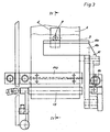
- FIG 4 is the lower position with dash-dotted lines of the gripper 10 moved with the aid of the support arm 11.
- This illustration also shows that a cutting device is arranged in the region between the two end positions of the gripper 10, with the aid of which the beginning of the web A pulled off the reel B is cut off, so that a new beginning of the web A1 is formed.
- the cutting device 14 consists of a cutting edge 14a which interacts with a recess in a pair of clamping jaws 14b, 14c.
- the clamping jaw 14c is resiliently supported with respect to the base part, so that when the pair of clamping jaws 14b, 14c are pressed together (as shown in dash-dotted lines in FIG. 4), the beginning of the web A is held between the clamping jaws 14b and 14c and at the same time the cutting edge 14a into Notch of the jaw 14b occurs. In this way, the front part of the beginning of the web A is cut off.
- the newly formed path start A1 is held by the upper part of the pair of jaws 14b, 14c.
- FIGS shows such a pair of transport rollers 15 which, after the gripper 10 has been moved into the lower end position, can be converted into the active position by a pressure medium cylinder 15a and, when it is driven, pulls off the start of web A in the desired length while simultaneously rotating the reel B, so that the separating cut made by the cutting edge 14a of the cutting device 14 can take place at any desired point.
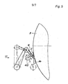
- the movable leg 10b of the gripper 10 is formed by a drivable pull-off roller 10d, so that the pair of transport rollers 15 according to FIG. 4 can be omitted if a larger length of the web start A is to be cut off.
- the embodiment according to FIG. 5 also shows, in connection with FIGS. 6 and 7, the arrangement of suction cups 16 laterally next to the centrally defined web start A. These suction cups 16 lift off the outer corners of the web start A before being gripped by the gripper 10, as shown in FIG this is shown in particular in FIG. 7 and FIG. 8 without the suction device 16 being shown.
- the vacuum required to suck in the corners of the start of the web A is generated in a suitable manner.
- the suction cups 16 can also be moved in a controlled manner according to FIG. 5 and only pressed onto the surface of the bobbin B for the required point in time.
- FIG. 8 it can be seen that when the suction cups 16 are used, the scraper 10a of the gripper 10 is provided with a central recess for the self-adhesive strip S.
- 9 shows a perspective view of the effect of the sensor 9, which in this case detects the self-adhesive strip S.
Landscapes
- Replacement Of Web Rolls (AREA)
- Sanitary Thin Papers (AREA)
Priority Applications (1)
| Application Number | Priority Date | Filing Date | Title |
|---|---|---|---|
| AT85116342T ATE47578T1 (de) | 1985-01-29 | 1985-12-20 | Vorrichtung zum erfassen und loesen des anfangs einer bobine. |
Applications Claiming Priority (2)
| Application Number | Priority Date | Filing Date | Title |
|---|---|---|---|
| DE19853502808 DE3502808A1 (de) | 1985-01-29 | 1985-01-29 | Vorrichtung zum erfassen und loesen des anfangs einer bobine |
| DE3502808 | 1985-01-29 |
Publications (3)
| Publication Number | Publication Date |
|---|---|
| EP0189582A2 true EP0189582A2 (fr) | 1986-08-06 |
| EP0189582A3 EP0189582A3 (en) | 1988-02-03 |
| EP0189582B1 EP0189582B1 (fr) | 1989-10-25 |
Family
ID=6260994
Family Applications (1)
| Application Number | Title | Priority Date | Filing Date |
|---|---|---|---|
| EP85116342A Expired EP0189582B1 (fr) | 1985-01-29 | 1985-12-20 | Dispositif pour saisir et détacher le début d'une bobine |
Country Status (4)
| Country | Link |
|---|---|
| US (1) | US4688736A (fr) |
| EP (1) | EP0189582B1 (fr) |
| AT (1) | ATE47578T1 (fr) |
| DE (2) | DE3502808A1 (fr) |
Cited By (8)
| Publication number | Priority date | Publication date | Assignee | Title |
|---|---|---|---|---|
| EP0227951A3 (en) * | 1985-11-28 | 1988-08-03 | Sanjo Machine Works Ltd. | Apparatus for continuously supplying sheets from supply rolls |
| EP0331634A1 (fr) * | 1988-02-25 | 1989-09-06 | Fabriques De Tabac Reunies S.A. | Procédé et appareil d'ouverture d'une bobine faite d'une bande de papier |
| WO1995029116A1 (fr) * | 1994-04-26 | 1995-11-02 | Massey University | Perfectionnements apportes a l'application d'un ruban adhesif |
| EP0692444A1 (fr) * | 1994-07-14 | 1996-01-17 | KOENIG & BAUER-ALBERT AKTIENGESELLSCHAFT | Matériau pour la fixation du début d'un rouleau de bande de papier |
| DE10219179A1 (de) * | 2002-04-29 | 2003-11-13 | Koenig & Bauer Ag | Vorrichtung zur Vorbereitung einer Materialrolle |
| DE10343451A1 (de) * | 2003-09-19 | 2005-04-14 | Voith Paper Patent Gmbh | Vorrichtung zum Entfernen von Lagen eines Wickels von einem Wickeltambour |
| DE10343452A1 (de) * | 2003-09-19 | 2005-04-14 | Voith Paper Patent Gmbh | Vorrichtung zum Entfernen von Lagen eines Wickels einer Faserstoffbahn von einer Wickeltrommel |
| WO2018172400A1 (fr) * | 2017-03-22 | 2018-09-27 | Philip Morris Products S.A. | Procédé de retrait d'une étiquette adhésive d'une bobine et appareil pour détacher une étiquette adhésive d'une partie d'extrémité d'une feuille enroulée en une bobine |
Families Citing this family (12)
| Publication number | Priority date | Publication date | Assignee | Title |
|---|---|---|---|---|
| US4911374A (en) * | 1986-01-21 | 1990-03-27 | Philip Morris Incorporated | System and method for use in delaminating bobbins of paper material |
| US4821972A (en) * | 1986-01-21 | 1989-04-18 | Philip Morris Incorporated | System and method for use in handling and delaminating bobbins of paper material |
| IT1238288B (it) * | 1990-03-27 | 1993-07-12 | Gd Spa | Dispositivo per l'asportazione di una fascetta adesiva di chiusura da una bobina di materiale in nastro. |
| IT1245766B (it) * | 1991-02-26 | 1994-10-14 | Gd Spa | Metodo e dispositivo per il taglio di una fascetta adesiva di chiusura di una bobina di materiale in nastro. |
| IT1257624B (it) * | 1992-01-09 | 1996-02-01 | Gd Spa | Dispositivo per il prelievo del capo del nastro di una bobina nuova ed il suo trasferimento ad una successiva stazione operativa |
| DE4212095C1 (fr) * | 1992-04-10 | 1993-08-19 | Man Roland Druckmaschinen Ag, 6050 Offenbach, De | |
| JP3127655B2 (ja) * | 1993-03-22 | 2001-01-29 | ソニー株式会社 | 変調装置及び復調装置 |
| DE10343420A1 (de) * | 2003-09-19 | 2005-04-14 | Voith Paper Patent Gmbh | Vorrichtung und Verfahren zum Entfernen von Ausschuss einer Materialbahn von einem Wickeltambour |
| DE10343446A1 (de) * | 2003-09-19 | 2005-04-14 | Voith Paper Patent Gmbh | Verfahren und Vorrichtung zur Entnahme mindestens eines Streifens von einem Wickel einer Materialbahn auf einem Wickeltambour |
| DE10343423A1 (de) * | 2003-09-19 | 2005-04-14 | Voith Paper Patent Gmbh | Vorrichtung und Verfahren zum Entfernen von Ausschuss einer Materialbahn von einem Wickeltambour |
| DE10343454A1 (de) * | 2003-09-19 | 2005-04-14 | Voith Paper Patent Gmbh | Anordnung mit einem Wickeltambour |
| DE102022128890A1 (de) * | 2022-11-01 | 2024-05-02 | Körber Technologies Gmbh | Anordnung zum automatischen Beladen einer Verbindungseinheit mit Bobinen |
Family Cites Families (8)
| Publication number | Priority date | Publication date | Assignee | Title |
|---|---|---|---|---|
| US1425076A (en) * | 1920-12-29 | 1922-08-08 | Dwight Fisk J | Reel |
| US2880778A (en) * | 1956-09-13 | 1959-04-07 | United States Steel Corp | Apparatus for pulling the end from a coil of strip |
| US3010672A (en) * | 1959-09-01 | 1961-11-28 | Jr Owen S Cecil | Coil opener and uncoiler |
| GB948723A (en) * | 1961-10-12 | 1964-02-05 | Beteiligungs & Patentverw Gmbh | Unwinding device for reels of strip material |
| GB1247296A (en) * | 1968-09-13 | 1971-09-22 | Hitachi Ltd | A method of and an apparatus for detecting the position of the end of a coil of strip material |
| US3767133A (en) * | 1970-09-09 | 1973-10-23 | Komatsu Mfg Co Ltd | Method of auto-loading of coiled material in blanking line |
| DE2361300A1 (de) * | 1973-12-08 | 1975-06-12 | Agfa Gevaert Ag | Klebemaschine und schneidevorrichtung |
| EP0048125B1 (fr) * | 1980-09-12 | 1984-08-29 | DAVY McKEE (POOLE) LIMITED | Appareil pour détecter la position de l'extrémité extérieure d'un bobinage de matériel en bande |
-
1985
- 1985-01-29 DE DE19853502808 patent/DE3502808A1/de not_active Withdrawn
- 1985-12-20 EP EP85116342A patent/EP0189582B1/fr not_active Expired
- 1985-12-20 AT AT85116342T patent/ATE47578T1/de not_active IP Right Cessation
- 1985-12-20 DE DE8585116342T patent/DE3573914D1/de not_active Expired
-
1986
- 1986-01-10 US US06/818,532 patent/US4688736A/en not_active Expired - Fee Related
Cited By (12)
| Publication number | Priority date | Publication date | Assignee | Title |
|---|---|---|---|---|
| EP0227951A3 (en) * | 1985-11-28 | 1988-08-03 | Sanjo Machine Works Ltd. | Apparatus for continuously supplying sheets from supply rolls |
| EP0331634A1 (fr) * | 1988-02-25 | 1989-09-06 | Fabriques De Tabac Reunies S.A. | Procédé et appareil d'ouverture d'une bobine faite d'une bande de papier |
| US4995406A (en) * | 1988-02-25 | 1991-02-26 | Fabriques De Tabac Reunies, S.A. | Apparatus and method for opening a reel of paper stripping |
| WO1995029116A1 (fr) * | 1994-04-26 | 1995-11-02 | Massey University | Perfectionnements apportes a l'application d'un ruban adhesif |
| EP0692444A1 (fr) * | 1994-07-14 | 1996-01-17 | KOENIG & BAUER-ALBERT AKTIENGESELLSCHAFT | Matériau pour la fixation du début d'un rouleau de bande de papier |
| DE10219179A1 (de) * | 2002-04-29 | 2003-11-13 | Koenig & Bauer Ag | Vorrichtung zur Vorbereitung einer Materialrolle |
| DE10219179B4 (de) * | 2002-04-29 | 2005-04-28 | Koenig & Bauer Ag | Vorrichtung zur Vorbereitung einer Materialrolle |
| DE10343451A1 (de) * | 2003-09-19 | 2005-04-14 | Voith Paper Patent Gmbh | Vorrichtung zum Entfernen von Lagen eines Wickels von einem Wickeltambour |
| DE10343452A1 (de) * | 2003-09-19 | 2005-04-14 | Voith Paper Patent Gmbh | Vorrichtung zum Entfernen von Lagen eines Wickels einer Faserstoffbahn von einer Wickeltrommel |
| WO2018172400A1 (fr) * | 2017-03-22 | 2018-09-27 | Philip Morris Products S.A. | Procédé de retrait d'une étiquette adhésive d'une bobine et appareil pour détacher une étiquette adhésive d'une partie d'extrémité d'une feuille enroulée en une bobine |
| RU2753967C2 (ru) * | 2017-03-22 | 2021-08-24 | Филип Моррис Продактс С.А. | Способ удаления клейкой этикетки с рулона и устройство для отделения клейкой этикетки от концевой части смотанного листа в рулоне |
| US11267669B2 (en) | 2017-03-22 | 2022-03-08 | Philip Morris Products S.A. | Method to remove an adhesive label from a bobbin and apparatus to detach an adhesive label from an end portion of a coiled sheet in a bobbin |
Also Published As
| Publication number | Publication date |
|---|---|
| EP0189582A3 (en) | 1988-02-03 |
| ATE47578T1 (de) | 1989-11-15 |
| EP0189582B1 (fr) | 1989-10-25 |
| US4688736A (en) | 1987-08-25 |
| DE3502808A1 (de) | 1986-07-31 |
| DE3573914D1 (en) | 1989-11-30 |
Similar Documents
| Publication | Publication Date | Title |
|---|---|---|
| EP0189582B1 (fr) | Dispositif pour saisir et détacher le début d'une bobine | |
| DE68904826T2 (de) | Verfahren und vorrichtung zum ersetzen von bahnfoermigem material in einer zufuehrvorrichtung fuer bahnfoermiges material. | |
| DE3751440T2 (de) | Vorrichtung zum Befestigen einer Ersatzbahn an eine sich bewegende Bahn. | |
| EP0638499B1 (fr) | Méthode et dispositif pour relier des bandes de matière, en particulier de matière d'emballage | |
| EP0940360B1 (fr) | Méthode et dispositif pour le raccordement de bandes | |
| DE4003504A1 (de) | Verfahren und vorrichtung zum automatischen wechseln einer vollen wickelrolle gegen eine neue wickelhuelse | |
| DE2506930C2 (de) | Verfahren und Vorrichtung zum Bilden einer Fadenreserve aus dem Fadenende einer Textilspule | |
| DE3918552C2 (de) | Maschine zum Vorbereiten von Papierrollen für den Spleißvorgang | |
| DE3441205A1 (de) | Bobinenwechselvorrichtung | |
| DE2223557C2 (de) | Verfahren zum Aufbringen von Aufklebern auf eine Endlosbahn | |
| DE69505334T2 (de) | Produktionsmaschine mit Bahnrollenzufuhr und Abfuhr leerer Kernhülsen | |
| EP0300220A2 (fr) | Méthode d'enroulage d'une matière à enrouler, alimentée sans interruption, sur plusieurs noyaux de bobinage, ainsi que bobineuse à deux tambours | |
| DE4436719A1 (de) | Spleißer für bobinenartig aufgewickelte Verpackungsmaterialbahnen | |
| EP0453711A1 (fr) | Procédé pour retirer et déposer une pile de feuilles poinçonnée ou des piles en matière feuilletée similaires d'une pile entière et dispositif pour celui-ci | |
| EP0379861B1 (fr) | Dispositif pour joindre des feuilles | |
| DE8502204U1 (de) | Vorrichtung zum Erfassen und Lösen des Anfangs einer Bobine | |
| DE19845842A1 (de) | Verfahren und Vorrichtung zur Herstellung einer Garnwicklung auf einer Spule | |
| DE2855138C2 (de) | Vorrichtung zum Abschneiden eines Haltebandes | |
| DE3531731C1 (de) | Vorrichtung zum kontinuierlichen Zufuehren eines bandfoermigen Materials zu einer Verarbeitungsmaschine | |
| DE4211984C2 (de) | Vorrichtung zum Bearbeiten einer Fadenreserve | |
| DE3925988A1 (de) | Vorrichtung zum loesen des hinterwindungsfadens von der oberflaeche von kopsen | |
| CH617409A5 (en) | System for jogging material sheets to form a stack | |
| DE2836480B2 (de) | Vorrichtung zum Aufnehmen und Drehen eines Bandbundes | |
| EP0406581A1 (fr) | Dispositif pour couper une bande sur un rouleau d'inversement | |
| WO2004013024A2 (fr) | Procede, systeme et dispositif pour preparer un rouleau de bobinage en vue d'un remplacement automatique, pour saisir une bande de produit et pour amener une bande adhesive double face sur une surface |
Legal Events
| Date | Code | Title | Description |
|---|---|---|---|
| PUAI | Public reference made under article 153(3) epc to a published international application that has entered the european phase |
Free format text: ORIGINAL CODE: 0009012 |
|
| AK | Designated contracting states |
Kind code of ref document: A2 Designated state(s): AT BE CH DE FR GB IT LI LU NL SE |
|
| PUAL | Search report despatched |
Free format text: ORIGINAL CODE: 0009013 |
|
| AK | Designated contracting states |
Kind code of ref document: A3 Designated state(s): AT BE CH DE FR GB IT LI LU NL SE |
|
| RAP1 | Party data changed (applicant data changed or rights of an application transferred) |
Owner name: NIEPMANN TRAYLIFT TRANSPORTSYSTEME GMBH & CO. KG |
|
| 17P | Request for examination filed |
Effective date: 19880628 |
|
| 17Q | First examination report despatched |
Effective date: 19881017 |
|
| GRAA | (expected) grant |
Free format text: ORIGINAL CODE: 0009210 |
|
| ITF | It: translation for a ep patent filed | ||
| AK | Designated contracting states |
Kind code of ref document: B1 Designated state(s): AT BE CH DE FR GB IT LI LU NL SE |
|
| PG25 | Lapsed in a contracting state [announced via postgrant information from national office to epo] |
Ref country code: SE Effective date: 19891025 Ref country code: NL Effective date: 19891025 Ref country code: BE Effective date: 19891025 |
|
| REF | Corresponds to: |
Ref document number: 47578 Country of ref document: AT Date of ref document: 19891115 Kind code of ref document: T |
|
| ET | Fr: translation filed | ||
| GBT | Gb: translation of ep patent filed (gb section 77(6)(a)/1977) | ||
| REF | Corresponds to: |
Ref document number: 3573914 Country of ref document: DE Date of ref document: 19891130 |
|
| PG25 | Lapsed in a contracting state [announced via postgrant information from national office to epo] |
Ref country code: AT Effective date: 19891220 |
|
| PG25 | Lapsed in a contracting state [announced via postgrant information from national office to epo] |
Ref country code: LU Free format text: LAPSE BECAUSE OF NON-PAYMENT OF DUE FEES Effective date: 19891231 Ref country code: LI Effective date: 19891231 Ref country code: CH Effective date: 19891231 |
|
| NLV1 | Nl: lapsed or annulled due to failure to fulfill the requirements of art. 29p and 29m of the patents act | ||
| PLBE | No opposition filed within time limit |
Free format text: ORIGINAL CODE: 0009261 |
|
| STAA | Information on the status of an ep patent application or granted ep patent |
Free format text: STATUS: NO OPPOSITION FILED WITHIN TIME LIMIT |
|
| REG | Reference to a national code |
Ref country code: CH Ref legal event code: PL |
|
| 26N | No opposition filed | ||
| ITTA | It: last paid annual fee | ||
| REG | Reference to a national code |
Ref country code: GB Ref legal event code: 732E |
|
| REG | Reference to a national code |
Ref country code: FR Ref legal event code: TP |
|
| PGFP | Annual fee paid to national office [announced via postgrant information from national office to epo] |
Ref country code: GB Payment date: 19971103 Year of fee payment: 13 |
|
| PGFP | Annual fee paid to national office [announced via postgrant information from national office to epo] |
Ref country code: FR Payment date: 19971117 Year of fee payment: 13 |
|
| PGFP | Annual fee paid to national office [announced via postgrant information from national office to epo] |
Ref country code: DE Payment date: 19980218 Year of fee payment: 13 |
|
| PG25 | Lapsed in a contracting state [announced via postgrant information from national office to epo] |
Ref country code: GB Free format text: LAPSE BECAUSE OF NON-PAYMENT OF DUE FEES Effective date: 19981220 |
|
| GBPC | Gb: european patent ceased through non-payment of renewal fee |
Effective date: 19981220 |
|
| PG25 | Lapsed in a contracting state [announced via postgrant information from national office to epo] |
Ref country code: FR Free format text: LAPSE BECAUSE OF NON-PAYMENT OF DUE FEES Effective date: 19990831 |
|
| REG | Reference to a national code |
Ref country code: FR Ref legal event code: ST |
|
| PG25 | Lapsed in a contracting state [announced via postgrant information from national office to epo] |
Ref country code: DE Free format text: LAPSE BECAUSE OF NON-PAYMENT OF DUE FEES Effective date: 19991001 |