EP0189639A1 - Pompe à rouleaux, à palettes ou pompe rotative similaire - Google Patents
Pompe à rouleaux, à palettes ou pompe rotative similaire Download PDFInfo
- Publication number
- EP0189639A1 EP0189639A1 EP85307736A EP85307736A EP0189639A1 EP 0189639 A1 EP0189639 A1 EP 0189639A1 EP 85307736 A EP85307736 A EP 85307736A EP 85307736 A EP85307736 A EP 85307736A EP 0189639 A1 EP0189639 A1 EP 0189639A1
- Authority
- EP
- European Patent Office
- Prior art keywords
- portions
- rotation
- rotor
- inlet port
- cam surface
- Prior art date
- Legal status (The legal status is an assumption and is not a legal conclusion. Google has not performed a legal analysis and makes no representation as to the accuracy of the status listed.)
- Withdrawn
Links
- 238000012384 transportation and delivery Methods 0.000 claims description 7
- 230000007423 decrease Effects 0.000 claims description 4
- 239000012530 fluid Substances 0.000 claims description 4
- 238000006073 displacement reaction Methods 0.000 abstract 1
- 238000007789 sealing Methods 0.000 description 10
- 241001131688 Coracias garrulus Species 0.000 description 6
- 239000007788 liquid Substances 0.000 description 5
- 238000010276 construction Methods 0.000 description 3
- 230000006835 compression Effects 0.000 description 2
- 238000007906 compression Methods 0.000 description 2
- 230000004323 axial length Effects 0.000 description 1
- 230000007425 progressive decline Effects 0.000 description 1
- 238000005096 rolling process Methods 0.000 description 1
Images
Classifications
-
- F—MECHANICAL ENGINEERING; LIGHTING; HEATING; WEAPONS; BLASTING
- F04—POSITIVE - DISPLACEMENT MACHINES FOR LIQUIDS; PUMPS FOR LIQUIDS OR ELASTIC FLUIDS
- F04C—ROTARY-PISTON, OR OSCILLATING-PISTON, POSITIVE-DISPLACEMENT MACHINES FOR LIQUIDS; ROTARY-PISTON, OR OSCILLATING-PISTON, POSITIVE-DISPLACEMENT PUMPS
- F04C15/00—Component parts, details or accessories of machines, pumps or pumping installations, not provided for in groups F04C2/00 - F04C14/00
- F04C15/06—Arrangements for admission or discharge of the working fluid, e.g. constructional features of the inlet or outlet
-
- F—MECHANICAL ENGINEERING; LIGHTING; HEATING; WEAPONS; BLASTING
- F01—MACHINES OR ENGINES IN GENERAL; ENGINE PLANTS IN GENERAL; STEAM ENGINES
- F01C—ROTARY-PISTON OR OSCILLATING-PISTON MACHINES OR ENGINES
- F01C21/00—Component parts, details or accessories not provided for in groups F01C1/00 - F01C20/00
- F01C21/10—Outer members for co-operation with rotary pistons; Casings
- F01C21/104—Stators; Members defining the outer boundaries of the working chamber
- F01C21/106—Stators; Members defining the outer boundaries of the working chamber with a radial surface, e.g. cam rings
-
- F—MECHANICAL ENGINEERING; LIGHTING; HEATING; WEAPONS; BLASTING
- F04—POSITIVE - DISPLACEMENT MACHINES FOR LIQUIDS; PUMPS FOR LIQUIDS OR ELASTIC FLUIDS
- F04C—ROTARY-PISTON, OR OSCILLATING-PISTON, POSITIVE-DISPLACEMENT MACHINES FOR LIQUIDS; ROTARY-PISTON, OR OSCILLATING-PISTON, POSITIVE-DISPLACEMENT PUMPS
- F04C2/00—Rotary-piston machines or pumps
- F04C2/30—Rotary-piston machines or pumps having the characteristics covered by two or more groups F04C2/02, F04C2/08, F04C2/22, F04C2/24 or having the characteristics covered by one of these groups together with some other type of movement between co-operating members
- F04C2/34—Rotary-piston machines or pumps having the characteristics covered by two or more groups F04C2/02, F04C2/08, F04C2/22, F04C2/24 or having the characteristics covered by one of these groups together with some other type of movement between co-operating members having the movement defined in groups F04C2/08 or F04C2/22 and relative reciprocation between the co-operating members
- F04C2/344—Rotary-piston machines or pumps having the characteristics covered by two or more groups F04C2/02, F04C2/08, F04C2/22, F04C2/24 or having the characteristics covered by one of these groups together with some other type of movement between co-operating members having the movement defined in groups F04C2/08 or F04C2/22 and relative reciprocation between the co-operating members with vanes reciprocating with respect to the inner member
- F04C2/3446—Rotary-piston machines or pumps having the characteristics covered by two or more groups F04C2/02, F04C2/08, F04C2/22, F04C2/24 or having the characteristics covered by one of these groups together with some other type of movement between co-operating members having the movement defined in groups F04C2/08 or F04C2/22 and relative reciprocation between the co-operating members with vanes reciprocating with respect to the inner member the inner and outer member being in contact along more than one line or surface
- F04C2/3447—Rotary-piston machines or pumps having the characteristics covered by two or more groups F04C2/02, F04C2/08, F04C2/22, F04C2/24 or having the characteristics covered by one of these groups together with some other type of movement between co-operating members having the movement defined in groups F04C2/08 or F04C2/22 and relative reciprocation between the co-operating members with vanes reciprocating with respect to the inner member the inner and outer member being in contact along more than one line or surface the vanes having the form of rollers, slippers or the like
Definitions
- This invention relates to rotary pumps and more particularly concerns pumps of the kind comprising a housing accommodating a rotor provided with radial slots in which are mounted vanes, rollers or other forms of piston movable radially in the slots and engaging a circumferentially-extending cam surface provided internally of the housing, the housing further providing an inlet port and two or more outlet ports circumferentially spaced from each other and from the inlet port, so that rotation of the rotor causes fluid from the inlet port to be delivered to both or as the case may be all of said outlet ports.
- the profiles of said two portions are such that as two pistons move along said two portions respectively, which pistons jointly determine the instantaneous delivery through said one outlet port, the difference between the squares of the radii of said two portions relative to the axis of rotation of the rotor at the instantaneous points of contact of said two pistons with the two portions respectively is a constant.
- the two said radii may be constant, but in order to give improved sealing contact between the pistons and the cam surface it may be preferred in some cases to reduce the two radii progressively in the direction of rotation of the rotor.
- the invention also provides a pump of the kind referred to wherein said cam surface where it extends between the inlet port and the next adjacent outlet port in the direction of rotation of the rotor and/or between at least one pair of next adjacent outlet ports is circular in profile and is centred on the axis of rotation of the rotor.
- the part of the cam surface extending circumferentially between each port and each of the two next adjacent flanking ports is circular in profile and is centred on the axis of rotation of the rotor.
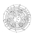
- the rotary pump shown is of the kind known as a roller pump and comprises a rotor 10 having in its periphery radially extending slots 11 which are equiangularly spaced about the axis of rotation 20 and in which are disposed rollers 12a to 12f respectively.
- the rollers are urged outwardly by centrifugal force into rolling engagement with the internal surface of a housing 13 surrounding the rotor, which surface is a cam surface controlling the inward and outward movement of the rollers as the rotor rotates.
- the rotor rotates anticlockwise as viewed in the drawing.
- an end member 13a of the housing provides an inlet port 14 and two outlet ports 15, 16 circumferentially spaced apart about the axis of the rotor and sealed with respect to each other.
- the adjacent edges of each adjacent pair of the ports are spaced apart by a distance not less than the distance between the points of contact of each pair of adjacent rollers with the cam surface, so that there is always at least one roller disposed between the said edges and forming a seal between them.
- Each of these sealing arcs is of circular profile centred on the axis of rotation 20 of the rotor, and the radii of these arcs are shown as R 1 , R 2 and R 3 respectively, R 1 being the radius of are 17 extending through angle ⁇ 1 between the inlet port 14 and the first outlet port 15, R 2 being the radius of arc 18 through angle ⁇ 5 extending between the two outlet ports 15, 16 and R 3 being the radius of arc 19 through angle &3 extending between the second outlet port 16 and the inlet port 14. Between arcs 19 and 17, i.e.
- Each of the ports instantaneously is sealed off from the other ports by two rollers which are in contact with the sealing arcs flanking the port.
- port 14 is sealed by rollers 12a and 12c (roller 12b being ineffective for that purpose) but 12c is also about to become a non-sealing roller and port 14 will then be sealed by rollers 12a and 12d and the instantaneous difference in the radii of their points of contact with the cam surface will then determine the instantaneous increase in volume open to the inlet port and hence the rate of flow of fluid through the inlet port.
- port 15 is sealed by rollers 12a and 12f which therefore determine the flow through the port
- port 16 is sealed by rollers 12e and 12d which therefore determine the flow through port 16.
- the length of arcs 17, 18 and 19 would be reduced and the number of non-sealing rollers (i.e. rollers in contact with the arcs 21, 22, 23) at any instant would be greater than in the illustrated construction.
- Ports 14, 15 and 16 are respectively in permanently open communication, through passages (not shown) in the end member 13a, with ports 14a, 15a and 16a. Ports 14a, 15a and 16a are opened and closed substantially simultaneously with their respective associated ports 14, 15 and 16.
- the instantaneous volume of liquid pumped through the first outlet 15 for a pump of axial length L is ⁇ (R 1 2 - R 2 2 ) x L x speed of rotation
- the required value of R 2 can therefore be calculated.
- the instantaneous volume of liquid pumped through the second outlet 16 is ⁇ (R22 - R 3 2 ) x L x speed rotation so that for a given output at the second outlet port, R 2 having been determined, R 3 can be calculated .
- the connecting arc 22 between sealing arcs 17 and 18 may, as in the case of arc 21 described above, provide a degree of over-filling and consequential pre-compression of the liquid over the length of the sealing arc 18.
- the sealing arc 19 may vary, if desired, from the circular profile described above, since the noise level at low pressure deliveries is less pronounced than at high pressure deliveries.
- the slots for the rollers in the pump shown in the drawings are divergent in an outward direction and the second output pressure at the second outlet should be higher than at the first outlet in order to avoid movement of the rollers across the width of the slots, but the slots may be parallel-sided.
- the invention is equally applicable to sliding vane pumps and other radially-moving piston type rotary pumps.
- the invention is also applicable to pumps of the kind referred to having an inlet port and more than two outlet ports spaced circumferentially and sealed from each other.
- R 1 does not remain constant over the length of the sealing arc, but for example gradually decreases thereby ensuring that the roller always remains in contact
- R 2 will also vary such that the instantaneous value of R 2 satisfies the formula:
- R 1 is kept constant and hence R 2 and R 3 are also constant.
Landscapes
- Engineering & Computer Science (AREA)
- Mechanical Engineering (AREA)
- General Engineering & Computer Science (AREA)
- Rotary Pumps (AREA)
- Details And Applications Of Rotary Liquid Pumps (AREA)
Applications Claiming Priority (2)
| Application Number | Priority Date | Filing Date | Title |
|---|---|---|---|
| GB848427354A GB8427354D0 (en) | 1984-10-30 | 1984-10-30 | Rotary pumps |
| GB8427354 | 1984-11-30 |
Publications (1)
| Publication Number | Publication Date |
|---|---|
| EP0189639A1 true EP0189639A1 (fr) | 1986-08-06 |
Family
ID=10568938
Family Applications (1)
| Application Number | Title | Priority Date | Filing Date |
|---|---|---|---|
| EP85307736A Withdrawn EP0189639A1 (fr) | 1984-10-30 | 1985-10-25 | Pompe à rouleaux, à palettes ou pompe rotative similaire |
Country Status (3)
| Country | Link |
|---|---|
| US (1) | US4659296A (fr) |
| EP (1) | EP0189639A1 (fr) |
| GB (1) | GB8427354D0 (fr) |
Cited By (3)
| Publication number | Priority date | Publication date | Assignee | Title |
|---|---|---|---|---|
| GB2334760A (en) * | 1997-10-16 | 1999-09-01 | Kit Systems Limited | Vane pumps or motors |
| FR3033609A1 (fr) * | 2015-03-09 | 2016-09-16 | Yves Gringoz | Guidage hydrostatique a report de pression |
| EP2625428A4 (fr) * | 2010-10-05 | 2017-10-18 | Magna Powertrain Inc. | Pompe à sortie double |
Families Citing this family (11)
| Publication number | Priority date | Publication date | Assignee | Title |
|---|---|---|---|---|
| US4828468A (en) * | 1985-02-25 | 1989-05-09 | Eaton Corporation | Balanced roller vane pump having reduced pressure pulses |
| DE8717456U1 (de) * | 1987-08-26 | 1988-12-29 | INTERATOM GmbH, 5060 Bergisch Gladbach | Rotationskolbenpumpe mit ungleichmäßiger Pumpleistung, insbesondere zur Ventilsteuerung von Verbrennungskraftmaschinen |
| RU2143570C1 (ru) * | 1999-06-03 | 1999-12-27 | Поляков Виктор Иванович | Двигатель полякова в.и., энергоблок теплоэлектростанции, топливоприготовительный агрегат, сепаратор газовый центробежный, центробежный парогазовый сепаратор, теплообменник трубчатый |
| GB9922360D0 (en) * | 1999-09-22 | 1999-11-24 | Hobourn Automotive Ltd | Improvements relating to pumps |
| US6857862B2 (en) | 2003-05-01 | 2005-02-22 | Sauer-Danfoss Inc. | Roller vane pump |
| US7299629B2 (en) * | 2004-02-18 | 2007-11-27 | Sauer-Danfoss Inc. | Charge/auxiliary circuit for reducing power losses in hydrostatic systems |
| US8113804B2 (en) * | 2008-12-30 | 2012-02-14 | Hamilton Sundstrand Corporation | Vane pump with rotating cam ring and increased under vane pressure |
| US8608465B2 (en) * | 2011-06-30 | 2013-12-17 | Peopleflo Manufacturing, Inc. | Positive-displacement rotary pump having a positive-displacement auxiliary pumping system |
| DE102018122306A1 (de) * | 2018-09-12 | 2020-03-12 | Fte Automotive Gmbh | Pumpenaggregat zur Bereitstellung eines Hydraulikdrucks zur Betätigung eines Aktors im Antriebsstrang eines Kraftfahrzeugs |
| DE102020105172A1 (de) * | 2020-02-27 | 2021-09-02 | Fte Automotive Gmbh | Drehschieberpumpe |
| RU2740235C1 (ru) * | 2020-09-07 | 2021-01-12 | Владимир Николаевич Благочиннов | Многоканальный роликовый насос |
Citations (4)
| Publication number | Priority date | Publication date | Assignee | Title |
|---|---|---|---|---|
| GB856687A (en) * | 1957-04-08 | 1960-12-21 | Hobourn Eaton Mfg Co Ltd | Improvements in rotary pumps |
| GB1178635A (en) * | 1967-01-03 | 1970-01-21 | Chrysler Corp | Improved Rotary Positive-Displacement Hydraulic Pump |
| US4080124A (en) * | 1974-11-04 | 1978-03-21 | Trw Inc. | Optimum porting configuration for a slipper seal pump |
| DE3219468A1 (de) * | 1981-05-25 | 1982-12-23 | Jidosha Kiki Co., Ltd., Tokyo | Oelpumpe |
Family Cites Families (3)
| Publication number | Priority date | Publication date | Assignee | Title |
|---|---|---|---|---|
| US2832199A (en) * | 1953-04-30 | 1958-04-29 | American Brake Shoe Co | Vane pump |
| US3025802A (en) * | 1957-04-08 | 1962-03-20 | Eaton Mfg Co | Rotary pump |
| US3066608A (en) * | 1960-11-22 | 1962-12-04 | William T Livermore | Multiple ported transmission pump |
-
1984
- 1984-10-30 GB GB848427354A patent/GB8427354D0/en active Pending
-
1985
- 1985-10-25 EP EP85307736A patent/EP0189639A1/fr not_active Withdrawn
- 1985-10-30 US US06/793,096 patent/US4659296A/en not_active Expired - Fee Related
Patent Citations (4)
| Publication number | Priority date | Publication date | Assignee | Title |
|---|---|---|---|---|
| GB856687A (en) * | 1957-04-08 | 1960-12-21 | Hobourn Eaton Mfg Co Ltd | Improvements in rotary pumps |
| GB1178635A (en) * | 1967-01-03 | 1970-01-21 | Chrysler Corp | Improved Rotary Positive-Displacement Hydraulic Pump |
| US4080124A (en) * | 1974-11-04 | 1978-03-21 | Trw Inc. | Optimum porting configuration for a slipper seal pump |
| DE3219468A1 (de) * | 1981-05-25 | 1982-12-23 | Jidosha Kiki Co., Ltd., Tokyo | Oelpumpe |
Cited By (3)
| Publication number | Priority date | Publication date | Assignee | Title |
|---|---|---|---|---|
| GB2334760A (en) * | 1997-10-16 | 1999-09-01 | Kit Systems Limited | Vane pumps or motors |
| EP2625428A4 (fr) * | 2010-10-05 | 2017-10-18 | Magna Powertrain Inc. | Pompe à sortie double |
| FR3033609A1 (fr) * | 2015-03-09 | 2016-09-16 | Yves Gringoz | Guidage hydrostatique a report de pression |
Also Published As
| Publication number | Publication date |
|---|---|
| US4659296A (en) | 1987-04-21 |
| GB8427354D0 (en) | 1984-12-05 |
Similar Documents
| Publication | Publication Date | Title |
|---|---|---|
| EP0189639A1 (fr) | Pompe à rouleaux, à palettes ou pompe rotative similaire | |
| US1771863A (en) | Rotary pump | |
| EP1320682B1 (fr) | Pompe a palettes a alimentation sous les palettes | |
| US8747085B2 (en) | Sliding vane pump with improved rotor profile | |
| US4484873A (en) | Through vane type rotary compressor with specific chamber configuration | |
| US4431389A (en) | Power transmission | |
| US4486150A (en) | Rotary pump and improved discharge port arrangement | |
| EP0058456A1 (fr) | Pompe ou moteur rotatif à palettes | |
| US3547562A (en) | Variable displacement vane pump | |
| US5738500A (en) | Variable displacement vane pump having low actuation friction cam seal | |
| US4432711A (en) | Vane pump with cylinder profile defined by cycloid curves | |
| CA2029609C (fr) | Elements obturateurs optimises accordes par impulsions pour pompe volumetrique | |
| US4551079A (en) | Rotary vane pump with two axially spaced sets of vanes | |
| EP0151983B1 (fr) | Pompe à palettes | |
| US5989002A (en) | Blocking-vane pump | |
| US3873246A (en) | Vane-type pump | |
| EP0057309B1 (fr) | Moteur à palettes coulissantes avec des moyens de poussée des palettes | |
| JP2601258B2 (ja) | 翼型又はローラー型の可変容量ポンプ | |
| US4511316A (en) | Positive displacement pumps | |
| US4025242A (en) | Vacuum pump oiling | |
| JP3865414B2 (ja) | ベーンポンプ | |
| KR102538954B1 (ko) | 로터리 압축기 | |
| CN112648180A (zh) | 叶片泵 | |
| US6425748B1 (en) | Positive displacement rotary pump | |
| US4529361A (en) | Vane pump having spokes with channel-shaped vanes |
Legal Events
| Date | Code | Title | Description |
|---|---|---|---|
| PUAI | Public reference made under article 153(3) epc to a published international application that has entered the european phase |
Free format text: ORIGINAL CODE: 0009012 |
|
| AK | Designated contracting states |
Kind code of ref document: A1 Designated state(s): AT DE FR GB IT SE |
|
| STAA | Information on the status of an ep patent application or granted ep patent |
Free format text: STATUS: THE APPLICATION IS DEEMED TO BE WITHDRAWN |
|
| 18D | Application deemed to be withdrawn |
Effective date: 19870209 |
|
| RIN1 | Information on inventor provided before grant (corrected) |
Inventor name: BRISTOW, IAN TREVOR |