EP0189708A1 - Générateur d'eau chaude à gaz - Google Patents
Générateur d'eau chaude à gaz Download PDFInfo
- Publication number
- EP0189708A1 EP0189708A1 EP85402597A EP85402597A EP0189708A1 EP 0189708 A1 EP0189708 A1 EP 0189708A1 EP 85402597 A EP85402597 A EP 85402597A EP 85402597 A EP85402597 A EP 85402597A EP 0189708 A1 EP0189708 A1 EP 0189708A1
- Authority
- EP
- European Patent Office
- Prior art keywords
- water
- jacket
- peripheral
- exchanger
- exchanger element
- Prior art date
- Legal status (The legal status is an assumption and is not a legal conclusion. Google has not performed a legal analysis and makes no representation as to the accuracy of the status listed.)
- Granted
Links
Images

Classifications
-
- F—MECHANICAL ENGINEERING; LIGHTING; HEATING; WEAPONS; BLASTING
- F24—HEATING; RANGES; VENTILATING
- F24H—FLUID HEATERS, e.g. WATER OR AIR HEATERS, HAVING HEAT-GENERATING MEANS, e.g. HEAT PUMPS, IN GENERAL
- F24H1/00—Water heaters, e.g. boilers, continuous-flow heaters or water-storage heaters
- F24H1/22—Water heaters other than continuous-flow or water-storage heaters, e.g. water heaters for central heating
- F24H1/40—Water heaters other than continuous-flow or water-storage heaters, e.g. water heaters for central heating with water tube or tubes
-
- F—MECHANICAL ENGINEERING; LIGHTING; HEATING; WEAPONS; BLASTING
- F24—HEATING; RANGES; VENTILATING
- F24H—FLUID HEATERS, e.g. WATER OR AIR HEATERS, HAVING HEAT-GENERATING MEANS, e.g. HEAT PUMPS, IN GENERAL
- F24H1/00—Water heaters, e.g. boilers, continuous-flow heaters or water-storage heaters
- F24H1/22—Water heaters other than continuous-flow or water-storage heaters, e.g. water heaters for central heating
- F24H1/24—Water heaters other than continuous-flow or water-storage heaters, e.g. water heaters for central heating with water mantle surrounding the combustion chamber or chambers
- F24H1/26—Water heaters other than continuous-flow or water-storage heaters, e.g. water heaters for central heating with water mantle surrounding the combustion chamber or chambers the water mantle forming an integral body
-
- F—MECHANICAL ENGINEERING; LIGHTING; HEATING; WEAPONS; BLASTING
- F24—HEATING; RANGES; VENTILATING
- F24H—FLUID HEATERS, e.g. WATER OR AIR HEATERS, HAVING HEAT-GENERATING MEANS, e.g. HEAT PUMPS, IN GENERAL
- F24H1/00—Water heaters, e.g. boilers, continuous-flow heaters or water-storage heaters
- F24H1/22—Water heaters other than continuous-flow or water-storage heaters, e.g. water heaters for central heating
- F24H1/44—Water heaters other than continuous-flow or water-storage heaters, e.g. water heaters for central heating with combinations of two or more of the types covered by groups F24H1/24 - F24H1/40
-
- F—MECHANICAL ENGINEERING; LIGHTING; HEATING; WEAPONS; BLASTING
- F24—HEATING; RANGES; VENTILATING
- F24H—FLUID HEATERS, e.g. WATER OR AIR HEATERS, HAVING HEAT-GENERATING MEANS, e.g. HEAT PUMPS, IN GENERAL
- F24H9/00—Details
- F24H9/0005—Details for water heaters
- F24H9/001—Guiding means
- F24H9/0015—Guiding means in water channels
Definitions
- the present invention relates to hot water generators heated with gas, liquefied gases or carbonated fuel oil and it aims to achieve a hot water generator of this type which is of economical construction.
- the invention also aims to avoid condensation in such a boiler in the chimney or combustion chamber which directly overcomes the burner.
- Yet another object of the present invention is to ensure, in the heat exchange circuit between the hot gases and the water, a circulation accelerated by the phenomenon of the thermo-siphon and to improve the heat exchange by one or several superheaters in which the. circulation is ensured, independently of the overall circulation of the water in the generator, by said thermo-siphon phenomenon.
- a gas boiler is described, the chimney of which is surrounded by a jacket which channels the water, taken from the periphery and from the base of a peripheral water reserve, up to a drawing-off basin located at the upper part of the reservoir, this drawing basin in direct communication with the upper part of the volume of water constituting the peripheral reserve.
- this peripheral jacket is provided in the chimney an axial channel fed at its base from the peripheral reserve and opening at its upper part into the drawing-off basin.
- the two circuits with circulation by thermo-siphon are therefore mounted in parallel with return of the water by diffusion in the volume of water of the peripheral reserve.
- FR-A-414223 describes a solid fuel boiler with, in the flow of hot gases, exchangers each consisting of a vertical tube with closed lower end in which is mounted a second axial tube open at its two ends, the upper ends of the two tubes being in communication with the water chamber to have a circulation by thermo-siphon with the descent of relatively cold water by the axial tube and the rise of the water heated by the peripheral jacket.
- each second exchanger element consists of an axial tube and a peripheral jacket and the arrival of water at this or these second exchanger elements takes place , from the top of the peripheral water jacket of the boiler, via the axial downflow tube of this second exchanger element and the outlet, from the top of the peripheral jacket of this second exchanger element, to an intermediate point in the circuit internal water circulation of the generator.
- the cylindrical boiler surrounds the central vertical chimney and is subdivided by walls into concentric cylindrical chambers communicating alternately at their high and low points, the arrival of the water to be heated or reheated taking place in the peripheral chamber and the departure of hot water at the high point of the most central chamber.
- the mass of water filling the boiler constitutes by itself the insulation, the largest part of the volume and the coldest being in contact with the outer wall.
- the walls other than that delimiting the central chimney which is in direct contact with the flame, remain at very low temperatures and they can be made of inexpensive materials such as plastics.
- the output of the second exchanger element (s) is connected to the high point of the second chamber of the boiler to ensure its mixing with water at medium temperature, the mixture remaining thermally insulated from the outside by the peripheral water jackets.
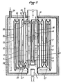
- the reference 1 designates the burner and the reference 2 s the chimney which surmounts the burner and in which the hot gases G circulate in the direction of the double arrows.
- a superheater designated by the general reference 3 which is constituted by a peripheral cylindrical tube 4 closed at its two ends and by a central tube 5 whose lower end is open.
- the chimney 2 is lined by a wall 6 so as to form in contact with the chimney 2 a water jacket 7.
- the boiler is delimited by a peripheral cylindrical casing 8 closed at its two ends and the internal volume is subdivided therefrom, in addition by the wall 6, by other concentric tubular walls 9 and 10 of so as to form water jackets in concentric chambers 11, 12 and 13.
- the tubular wall 6 is interrupted at a certain distance from the bottom of the casing 8 to provide a lower passage 14 between the chambers 11 and 6
- the wall 9 is interrupted at a certain distance from the upper wall of the casing 8 to provide an upper passage 15 between the chambers 11 and 12
- the wall 10 is interrupted at a certain distance from the bottom of the envelope to provide a lower passage 16 between the chambers 13 and 12.
- the central tube 5 of the superheater 3 is connected at its upper part by one or more tubes 17 with the high point of the central water jacket 7 while the high point of the peripheral water jacket 18 of the superheater 3 produced between the tubes 4 and 5 is connected, by one or more tubes 19, with the upper part of the chamber 11.
- the water to be heated arrives via the tube 20 connected to the upper part of the chamber 13 and the drawing is carried out by a tube 21.
- the water circulation is materialized by arrows with single point E.
- the water arrives by the tube 20 substantially at room temperature and descends into the chamber 13 at low speed given the large section of this chamber. It then passes through the passage 16 and goes back up into the chamber 12, passes at the top of the latter through the passage 15 and descends into the chamber 11 while heating by heat exchange through the wall 6 and also by injection of a current hot water from the superheater as explained below.
- the water passes into the chamber 6 through the passage 14 and circulates in the latter in the upward direction under the effect of the water withdrawal by the tube 21 and the phenomenon of thermo-siphon which takes birth in room 6 and in the superheater 3.
- the column of water in the chamber 6 heats up by direct exchange with the hot gases through the wall 2 and the part of the ascending current which is not withdrawn by the tube 21 is discharged by the tube or tubes. 17 in the central tube 5 of the superheater 3.
- This stream of water descends in the central tube 5 of the superheater and passes at the lower end of this tube in the peripheral chamber 18 where it is intensively heated by direct exchange through the wall 4, which results in an acceleration of the flow rate resulting from the thermo-siphon phenomenon and this flow rate is returned by the tube or tubes 19 to the top of the chamber 11.
- It therefore occurs under the effect of the thermo phenomenon -siphon which begins intensively in chambers 6 and 18 an internal circulation of hot water which is independent of the drawing flow.
- This circulation is ascending in the chamber 6, passes through the tubes 17, is descending in the tube 5 and ascending in the chamber 18, passes through the tubes 19 and is descending in the chamber 11 where the circulating volume mixes with a flow coming from chamber 12 equal to the drawing flow.
- FIG. 2 the same references have been used to designate the elements equivalent to those of FIG. 1.
- the essential difference resides in the fact that the generator is in a closed circuit, the hot water circuit of the generator being enclosed in a tank. constituted by a wall 22 surrounded by a thermal insulation layer 23, the sanitary water arriving via a pipe 24 which is preferably extended, as illustrated in phantom in the. Figure 2 in 24 ', to the bottom of the reserve and being withdrawn by a pipe 25.
- the concentric chambers 11, 12 and 13 which are embedded in the volume of water in the balloon are each constituted by two cylindrical walls 26 crimped or welded at their two ends.
- the wall 6 is also welded at its two ends to the outer surface of the wall 2 delimiting the chimney.
- the passages 14, 15, 16 at the successively high and low points between the concentric chambers are produced by tubes 27 distributed at the periphery. Circulation in the water circuit constituted by chambers 7, 11, 12 and 13 is done only under the effect of the phenomenon of thermo-siphon in chamber 7 and it is done from the interior chamber towards the exterior chamber with return .from the bottom of the peripheral chamber 13 to the bottom of the chamber 7 by tubes 27.
- the ascending flow in the chamber 7 which results solely from the thermo-siphon phenomenon is distributed between a pumped flow, as illustrated by arrow 28, at top of the chamber 11 and a flow through the tube 17 to the tube 5 of the superheater, flow which is induced by the phenomenon of thermo-siphon in said superheater, this flow being reinjected by the tube 19 with the flow 28 to ensure circulation in chambers 11, 12 and 13.
- the invention ensures natural circulation in the exchange circuit with c a speed in said circuit, all the more reduced as the temperature difference between the water of the generator and the water to be heated is more reduced which promotes the heat exchange.
Landscapes
- Engineering & Computer Science (AREA)
- Physics & Mathematics (AREA)
- Thermal Sciences (AREA)
- Chemical & Material Sciences (AREA)
- Combustion & Propulsion (AREA)
- Mechanical Engineering (AREA)
- General Engineering & Computer Science (AREA)
- Heat-Exchange Devices With Radiators And Conduit Assemblies (AREA)
- Resistance Heating (AREA)
- Electrophonic Musical Instruments (AREA)
- Gas Separation By Absorption (AREA)
- Engine Equipment That Uses Special Cycles (AREA)
Abstract
Description
- La présente invention concerne les générateurs d'eau chaude chauffés au gaz, aux gaz liquéfiés ou au fuel gazéifié et elle a pour but de réaliser un générateur d'eau chaude de ce type qui soit d'une construction économique.
- L'invention a également pour but d'éviter dans une telle chaudière la condensation dans la cheminée ou chambre de combustion qui surmonte directement le brûleur.
- Un autre but encore de la présente invention est d'assurer, dans le circuit d'échange thermique entre les gaz chauds et l'eau, une circulation accélérée par le phénomène du thermo-siphon et d'améliorer l'échange thermique par un ou plusieurs surchauffeurs dans lesquels la. circulation est assurée, de façon indépendante de la circulation d'ensemble de l'eau dans le générateur, par ledit phénomène de thermo-siphon.
- Dans GB-A-154476 est décrite une chaudière à gaz dont la cheminée est entourée par une chemise qui canalise l'eau, prélevée à la périphérie et à la base d'une réserve d'eau périphérique, jusqu'à un bassin de puisage situé à la partie haute du réservoir, ce bassin de puisage en communication directe avec la partie supérieure du volume d'eau constituant la réserve périphérique. En parallèle avec cette chemise périphérique est prévu dans la cheminée un canal axial alimenté à sa base à partir de la réserve périphérique et débouchant à sa partie haute dans le bassin de puisage. Les deux circuits à circulation par thermo-siphon sont donc montés en parallèle avec retour de l'eau par diffusion dans le volume d'eau de la réserve périphérique.
- FR-A-414223 décrit une chaudière à combustible solide avec, dans le flux des gaz chauds, des échangeurs constitués chacun par un tube vertical à extrémité inférieure fermée dans lequel est monté un deuxième tube axial ouvert à ses deux extrémités, les extrémités supérieures des deux tubes étant en communication avec la chambre d'eau pour avoir une circulation par thermo-siphon avec descente de l'eau relativement froide par le tube axial et remontée de l'eau réchauffée par la chemise périphérique.
- Aucun de ces deux brevets ne suggère de réaliser la chaudière de manière que la partie de l'échangeur montée dans la cheminée centrale et qui est de ce fait isolée contre toute déperdition par échange thermique avec l'ambiance et se trouve à la température la plus élevée, constitue un surchauffeur efficace.
- Conformément à l'invention dans un générateur d'eau chaude à gaz comportant une cheminée verticale dans laquelle les .gaz chauds circulent selon un courant ascendant, la paroi de cette cheminée délimitant une chemise d'eau périphérique dans laquelle l'eau à chauffer arrive au point bas pour être évacuée au point haut de ladite chemise avec au moins un deuxième élément échangeur monté verticalement dans ladite cheminée, chaque deuxième élément échangeur est constitué par un tube axial et une chemise périphérique et l'arrivée d'eau à ce ou ces deuxièmes éléments échangeurs se fait, depuis le sommet de la chemise d'eau périphérique de la chaudière, par le tube axial à circulation descendante de ce deuxième élément échangeur et la sortie, depuis le sommet de la chemise périphérique de ce deuxième élément échangeur, vers un point intermédiaire du circuit de circulation d'eau interne du générateur.
- Dans le cas d'un générateur d'eau chaude sanitaire fonctionnant en circuit ouvert avec une arrivée et une sortie d'eau reliées à la chaudière, la chaudière cylindrique entoure la cheminée verticale centrale et elle est subdivisée par des parois en chambres cylindriques concentriques communiquant alternativement en leurs points hauts et bas, l'arrivée de l'eau à chauffer ou réchauffer se faisant dans la chambre périphérique et le départ de l'eau chaude au point haut de la chambre la plus centrale. Avec cette réalisation, la masse d'eau remplissant la chaudière constitue par elle-même le calorifugeage, la partie la plus importante du volume et la plus froide se trouvant au contact de la paroi extérieure. Les parois autres que celle délimitant la cheminée centrale qui se trouve au contact direct de la flamme, restent à des températures très basse et elles peuvent être réalisées en des matériaux bon marché tels que les matières plastiques.
- Dans le cas du générateur d'eau chaude en circuit ouvert ci-dessus, la sortie du ou des deuxièmes éléments échangeurs est branchée au point haut de la deuxième chambre de la chaudière pour assurer son mélange avec de l'eau à température .moyenne, le mélange restant isolé thermiquement de l'extérieur par les chemises d'eau périphériques.
- L'invention sera décrite plus en détail ci-après dans son application à un générateur d'eau chaude à circuit ouvert et dans son application à un générateur d'eau chaude en circuit fermé avec échange thermique dans un ballon d'eau sanitaire, applications décrites à titre d'exemples avec référence aux dessins schématiques ci-annexés dans lesquels:
- La figure 1 est une coupe axiale schématique d'un générateur d'eau chaude à circuit ouvert
- et la figure 2 est une coupe axiale schématique d'un ballon d'eau chaude sanitaire dont le circuit fermé d'eau chaude est réalisé conformément à l'invention.
- Dans les dessins la référence 1 désigne le brûleur et la s référence 2 la cheminée qui surmonte le brûleur et dans laquelle les gaz chauds G circulent dans le sens des double- flèches. Au centre de la cheminée 2 est monté un surchauffeur désigné par la référence générale 3 lequel est constitué par un tube cylindrique périphérique 4 fermé à ses deux extrémités et par un tube central 5 dont l'extrémité inférieure est ouverte. Dans les deux modes de réalisation la cheminée 2 est doublée par une paroi 6 de manière à former au contact de la cheminée 2 une chemise d'eau 7.
- Dans le générateur d'eau chaude à circuit ouvert la chaudière est délimitée par une enveloppe cylindrique périphérique 8 fermée à ses deux extrémités et le volume intérieur en est subdivisé,outre par la paroi 6,par d'autres parois tubulaires concentriques 9 et 10 de manière à former des chemises d'eau dans des chambres concentriques 11, 12 et 13. La paroi tubulaire 6 est interrompue à une certaine distance du fond de l'enveloppe 8 pour ménager un passage inférieur 14 entre les chambres 11 et 6, la paroi 9 est interrompue à une certaine distance de la paroi supérieure de l'enveloppe 8 pour ménager un passage supérieur 15 entre les chambres 11 et 12 et la paroi 10 est interrompue à une certaine distance du fond de l'enveloppe pour ménager un passage inférieur 16 entre les chambres 13 et 12.
- Le tube central 5 du surchauffeur 3 est connecté à sa partie supérieure par un ou plusieurs tubes 17 avec le point haut de la chemise d'eau centrale 7 tandis que le point haut de la chemise d'eau périphérique 18 du surchauffeur 3 réalisée entre les tubes 4 et 5 est connecté, par un ou plusieurs tubes 19, avec la partie supérieure de la chambre 11.
- L'eau à chauffer arrive par le tube 20 connecté à la partie supérieure de la chambre 13 et le puisage s'effectue par un tube 21. La circulation de l'eau est matérialisée par des flèches à simple pointe E. L'eau arrive par le tube 20 sensiblement à la température de l'ambiance et descend dans la chambre 13 à faible vitesse étant donné la grande section de cette chambre. Elle passe ensuite par le passage 16 et remonte dans la chambre 12, passe au sommet de celle-ci par le passage 15 et redescend dans la chambre 11 en se réchauffant par échange thermique à travers la paroi 6 et également par injection d'un courant d'eau chaude provenant du surchauffeur comme expliqué ci-après. Au bas de la chambre 11 l'eau passe dans la chambre 6 par le passage 14 et circule dans celle-ci dans le sens ascendant sous l'effet du prélèvement d'eau par le tube 21 et du phénomène de thermo-siphon qui prend naissance dans la chambre 6 et dans le surchauffeur 3.
- En effet la colonne d'eau se trouvant dans la chambre 6 se réchauffe par échange direct avec les gaz chauds à travers la paroi 2 et la partie du courant ascendant qui n'est pas prélevée par le tube 21 est refoulée par le ou les tubes 17 dans le tube central 5 du surchauffeur 3. Ce courant d'eau descend dans le tube central 5 du surchauffeur et passe à l'extrémité inférieure de ce tube dans la chambre périphérique 18 où elle est chauffée de manière intense par échange direct à travers la paroi 4, ce qui entraîne une accélération du débit résultant du phénomène de thermo-siphon et ce débit est renvoyé par le ou les tubes 19 au sommet de la chambre 11. Il se produit donc sous l'effet du phénomène de thermo-siphon qui prend naissance de façon intense dans les chambres 6 et 18 une circulation interne de l'eau chaude qui est indépendante du débit de puisage. Cette circulation est ascendante dans la chambre 6, passe par les tubes 17, est descendante dans le tube 5 et ascendante dans la chambre 18, passe par les tubes 19 et est descendante dans la chambre 11 où le volume en circulation se mélange avec un débit provenant de la chambre 12 égal au débit de puisage.
- Du fait de ce fonctionnement, on obtient un meilleur échange thermique en raison de la vitesse d'écoulement, très supérieure à celle correspondant au simple débit de puisage, de l'eau au contact des parois léchées par les gaz chauds et une tendance à l'égalisation des températures en tous les points desdites parois. La partie de la chaudière où s'effectue cet échange thermique intense est calorifugée par la masse d'eau entrante qui circule dans les chambres 13 et 12 à une vitesse très faible du fait de la grande section de ces chambres et du débit réduit qui correspond au seul débit de puisage.
- Dans la figure 2 les mêmes références ont été utilisées pour désigner les éléments équivalents à ceux de la figure 1. La différence essentielle réside dans le fait que le générateur est en circuit fermé, le circuit d'eau chaude du générateur étant enfermé dans un ballon constitué par une paroi 22 entourée par une couche d'isolation thermique 23, l'eau sanitaire arrivant par une conduite 24 laquelle est de préférence prolongée, comme illustré en traits mixtes à la. figure 2 en 24', jusqu'au bas de la réserve et étant prélevée par une conduite 25. Les chambres concentriques 11, 12 et 13 qui sont noyées dans le volume d'eau du ballon sont constituées chacune par deux parois cylindriques 26 serties ou soudées à leurs deux extrémités. La paroi 6 est également soudée à ses deux extrémités sur la surface extérieure de la paroi 2 délimitant la cheminée. Les passages 14, 15, 16 aux points successivement haut et bas entre les chambres concentriques sont réalisés par des tubes 27 répartis à la périphérie. La circulation dans le circuit d'eau constitué par les chambres 7, 11, 12 et 13 se fait uniquement sous l'effet du phénomène de thermo-siphon dans la chambre 7 et elle se fait de la chambre intérieure vers la chambre extérieure avec retour.du bas de la chambre périphérique 13 au bas de la chambre 7 par des tubes 27. Le débit ascendant dans la chambre 7 qui résulte uniquement du phénomène de thermo-siphon se répartit entre un débit refoulé, comme illustré par la flèche 28, au sommet de la chambre 11 et un débit par le tube 17 vers le tube 5 du surchauffeur, débit qui est induit par le phénomène de thermo-siphon dans ledit surchauffeur, ce débit étant réinjecté par le tube 19 avec le débit 28 pour assurer la circulation dans les chambres 11, 12 et 13. Outre l'amélioration de l'échange thermique avec les gaz chauds résultant de la vitesse de circulation au contact des parois chauffées par les gaz ci-dessus décrite, l'invention assure une circulation naturelle dans le circuit d'échange avec une vitesse dans ledit circuit, d'autant plus réduite que la différence des températures entre l'eau du générateur et l'eau à chauffer est plus réduite ce qui favorise l'échange calorifique. Il est évident que les chambres 11, 12 et 13 et leurs tubes de connexion pourraient être remplacés par un serpentin raccordant les tubes 19 et 27 en bénéficiant de la circulation induite par la chambre 7 et le surchauffeur 3 mais la vitesse d'écoulement serait constante tout au long du circuit d'échange ce qui supprimerait l'avantage ci-dessus d'une vitesse d'écoulement au contact des parois d'autant plus faible que la différence des températures des liquides .participant à l'échange est plus faible.
- Les modes de réalisation ci-dessus décrits à titre d'exemples sont susceptibles de recevoir diverses modifications sans sortir du cadre des revendications. C'est ainsi que plusieurs générateurs à circuit ouvert tels que décrits avec référence à la figure 1 peuvent être branchés en parallèles pour former une batterie et accroître la puissance de l'installation. Il est également possible de faire fonctionner l'installation avec un accélérateur à débit variable ou à fonctionnement contrôlé par sonde ou aquastat de façon connue. Enfin en accroissant le diamètre de la cheminée ou chambre de combustion 2 il est possible de monter une pluralité de surchauffeurs, par exemple au moins trois pour des raisons de symétrie, ces surchauffeurs étant branchés en parallèle.
Claims (3)
caractérisé en ce que chaque deuxième élément échangeur est constitué par un tube axial et une chemise périphérique, l' arrivée d'eau à ce ou ces deuxièmes éléments échangeurs se fait, depuis le sommet de la chemise d'eau périphérique (7) de la chaudière, par le tube axial (5) à circulation descendante de ce deuxième élément échangeur et la sortie, depuis le sommet de la chemise périphérique (18) de ce deuxième élément échangeur vers un point intermédiaire (19) du circuit de circulation d'eau interne du générateur.
Priority Applications (1)
| Application Number | Priority Date | Filing Date | Title |
|---|---|---|---|
| AT85402597T ATE56087T1 (de) | 1984-12-26 | 1985-12-23 | Gaswassererhitzer. |
Applications Claiming Priority (2)
| Application Number | Priority Date | Filing Date | Title |
|---|---|---|---|
| FR8419826 | 1984-12-26 | ||
| FR8419826A FR2575274B1 (fr) | 1984-12-26 | 1984-12-26 | Generateur d'eau chaude a gaz avec surchauffeur et circulation par thermo-siphon |
Publications (2)
| Publication Number | Publication Date |
|---|---|
| EP0189708A1 true EP0189708A1 (fr) | 1986-08-06 |
| EP0189708B1 EP0189708B1 (fr) | 1990-08-29 |
Family
ID=9310980
Family Applications (1)
| Application Number | Title | Priority Date | Filing Date |
|---|---|---|---|
| EP85402597A Expired - Lifetime EP0189708B1 (fr) | 1984-12-26 | 1985-12-23 | Générateur d'eau chaude à gaz |
Country Status (4)
| Country | Link |
|---|---|
| EP (1) | EP0189708B1 (fr) |
| AT (1) | ATE56087T1 (fr) |
| DE (1) | DE3579442D1 (fr) |
| FR (1) | FR2575274B1 (fr) |
Cited By (2)
| Publication number | Priority date | Publication date | Assignee | Title |
|---|---|---|---|---|
| FR2751735A1 (fr) * | 1996-07-29 | 1998-01-30 | Deville Sa | Chaudiere de chauffage central a bruleur fioul |
| CN114688899A (zh) * | 2020-12-31 | 2022-07-01 | 广东万和新电气股份有限公司 | 换热装置及换热组件 |
Families Citing this family (1)
| Publication number | Priority date | Publication date | Assignee | Title |
|---|---|---|---|---|
| RU2146789C1 (ru) * | 1998-12-07 | 2000-03-20 | Общество с ограниченной ответственностью "Белэнергомаш" | Вертикальный водогрейный водотрубный котел |
Citations (8)
| Publication number | Priority date | Publication date | Assignee | Title |
|---|---|---|---|---|
| FR414223A (fr) * | 1910-03-30 | 1910-08-29 | Leon Nanquette | Chaudière pour chauffage à vapeur ou à eau chaude |
| GB154476A (en) * | 1920-01-10 | 1920-12-02 | Henry Chalk Webb | Improvements in and connected with single tank apparatus for heating water |
| GB321044A (en) * | 1928-10-12 | 1929-10-31 | Albert Archie Stow | Improvements in geysers and other heaters for liquid |
| US1754102A (en) * | 1927-03-09 | 1930-04-08 | Samuel B Harding | Boiler |
| FR826477A (fr) * | 1937-09-09 | 1938-03-31 | Chauffe-eau à accumulation, chauffé au mazout | |
| FR965609A (fr) * | 1950-09-16 | |||
| FR1095505A (fr) * | 1953-12-08 | 1955-06-03 | Chaudière haute pression à vapeur ou eau chaude | |
| US4397297A (en) * | 1981-03-11 | 1983-08-09 | Wie Chwang T | Water heater heat reclaimer |
-
1984
- 1984-12-26 FR FR8419826A patent/FR2575274B1/fr not_active Expired
-
1985
- 1985-12-23 EP EP85402597A patent/EP0189708B1/fr not_active Expired - Lifetime
- 1985-12-23 DE DE8585402597T patent/DE3579442D1/de not_active Expired - Lifetime
- 1985-12-23 AT AT85402597T patent/ATE56087T1/de not_active IP Right Cessation
Patent Citations (8)
| Publication number | Priority date | Publication date | Assignee | Title |
|---|---|---|---|---|
| FR965609A (fr) * | 1950-09-16 | |||
| FR414223A (fr) * | 1910-03-30 | 1910-08-29 | Leon Nanquette | Chaudière pour chauffage à vapeur ou à eau chaude |
| GB154476A (en) * | 1920-01-10 | 1920-12-02 | Henry Chalk Webb | Improvements in and connected with single tank apparatus for heating water |
| US1754102A (en) * | 1927-03-09 | 1930-04-08 | Samuel B Harding | Boiler |
| GB321044A (en) * | 1928-10-12 | 1929-10-31 | Albert Archie Stow | Improvements in geysers and other heaters for liquid |
| FR826477A (fr) * | 1937-09-09 | 1938-03-31 | Chauffe-eau à accumulation, chauffé au mazout | |
| FR1095505A (fr) * | 1953-12-08 | 1955-06-03 | Chaudière haute pression à vapeur ou eau chaude | |
| US4397297A (en) * | 1981-03-11 | 1983-08-09 | Wie Chwang T | Water heater heat reclaimer |
Cited By (2)
| Publication number | Priority date | Publication date | Assignee | Title |
|---|---|---|---|---|
| FR2751735A1 (fr) * | 1996-07-29 | 1998-01-30 | Deville Sa | Chaudiere de chauffage central a bruleur fioul |
| CN114688899A (zh) * | 2020-12-31 | 2022-07-01 | 广东万和新电气股份有限公司 | 换热装置及换热组件 |
Also Published As
| Publication number | Publication date |
|---|---|
| FR2575274A1 (fr) | 1986-06-27 |
| EP0189708B1 (fr) | 1990-08-29 |
| ATE56087T1 (de) | 1990-09-15 |
| FR2575274B1 (fr) | 1989-06-16 |
| DE3579442D1 (de) | 1990-10-04 |
Similar Documents
| Publication | Publication Date | Title |
|---|---|---|
| EP1618341B1 (fr) | Echangeur de chaleur a condensation | |
| EP2531779B1 (fr) | Dispositif de production de fluides chauds comprenant un echangeur de chaleur a condensation | |
| EP0172087B1 (fr) | Appareil de production d'air chaud et d'eau chaude sanitaire | |
| EP0037333A1 (fr) | Chaudière à gaz pouvant fonctionner en circuit de combustion étanche | |
| EP0350388A1 (fr) | Perfectionnements aux appareils de production d'eau chaude | |
| FR2656074A1 (fr) | Echangeur de chaleur pour appareil de chauffage a gaz ainsi qu'appareil de chauffage a gaz comprenant un tel echangeur de chaleur. | |
| EP0006774B1 (fr) | Brûleur pour combustible liquide | |
| EP0189708B1 (fr) | Générateur d'eau chaude à gaz | |
| FR2654200A1 (fr) | Chaudiere de chauffage central et/ou de production d'eau chaude sanitaire et installation de chauffage central et de production d'eau chaude sanitaire utilisant la dite chaudiere. | |
| FR2514475A1 (fr) | Chaudiere de petite puissance pour installations de chauffage | |
| EP0395457B1 (fr) | Procédé et appareil de chauffage d'un flux de fluide gazeux par échanges thermiques successifs | |
| FR2479428A1 (fr) | Chaudiere a gaz pouvant fonctionner en circuit de combustion etanche | |
| FR3033027A1 (fr) | Alambic equipe d'un tour a feu avec isolation renforcee | |
| CH645182A5 (fr) | Dispositif echangeur de chaleur courbe pour le chauffage et la climatisation solaires de locaux. | |
| EP0429371B1 (fr) | Corps de chaudière de chauffage à fluide caloporteur | |
| EP0403326B1 (fr) | Perfectionnements aux ballons d'eau chaude et aux installations équipées de tels ballons | |
| EP0456582B1 (fr) | Chaudière à condensation et fluide caloporteur | |
| FR1402699A (fr) | Générateur de chaleur notamment pour la production d'eau chaude | |
| WO1992019920A1 (fr) | Chaudiere de chauffage central et/ou de production d'eau chaude sanitaire, bruleur pour combustible gazeux, et installation de chauffage central et de production d'eau chaude sanitaire utilisant ladite chaudiere | |
| FR2478796A1 (fr) | Appareil de chauffage, notamment d'eau | |
| FR2468852A1 (fr) | Chaudiere, notamment pour installations de chauffage domestique | |
| EP1098147A1 (fr) | Chaudière de chauffage du type vertical | |
| FR2521269A1 (fr) | Chaudiere equipee d'un echangeur a condensation et d'un bruleur a combustible liquide | |
| EP0549416A1 (fr) | Brûleur perfectionné à grille ainsi qu'installation de chauffage équipée d'un tel brûleur | |
| BE569071A (fr) |
Legal Events
| Date | Code | Title | Description |
|---|---|---|---|
| PUAI | Public reference made under article 153(3) epc to a published international application that has entered the european phase |
Free format text: ORIGINAL CODE: 0009012 |
|
| AK | Designated contracting states |
Kind code of ref document: A1 Designated state(s): AT BE CH DE GB IT LI LU NL SE |
|
| 17P | Request for examination filed |
Effective date: 19870123 |
|
| 17Q | First examination report despatched |
Effective date: 19871013 |
|
| GRAA | (expected) grant |
Free format text: ORIGINAL CODE: 0009210 |
|
| AK | Designated contracting states |
Kind code of ref document: B1 Designated state(s): AT BE CH DE GB IT LI LU NL SE |
|
| PG25 | Lapsed in a contracting state [announced via postgrant information from national office to epo] |
Ref country code: AT Effective date: 19900829 |
|
| REF | Corresponds to: |
Ref document number: 56087 Country of ref document: AT Date of ref document: 19900915 Kind code of ref document: T |
|
| REF | Corresponds to: |
Ref document number: 3579442 Country of ref document: DE Date of ref document: 19901004 |
|
| ITF | It: translation for a ep patent filed | ||
| GBT | Gb: translation of ep patent filed (gb section 77(6)(a)/1977) | ||
| ITTA | It: last paid annual fee | ||
| PLBE | No opposition filed within time limit |
Free format text: ORIGINAL CODE: 0009261 |
|
| STAA | Information on the status of an ep patent application or granted ep patent |
Free format text: STATUS: NO OPPOSITION FILED WITHIN TIME LIMIT |
|
| 26N | No opposition filed | ||
| PGFP | Annual fee paid to national office [announced via postgrant information from national office to epo] |
Ref country code: LU Payment date: 19931216 Year of fee payment: 9 |
|
| PGFP | Annual fee paid to national office [announced via postgrant information from national office to epo] |
Ref country code: GB Payment date: 19931217 Year of fee payment: 9 |
|
| PGFP | Annual fee paid to national office [announced via postgrant information from national office to epo] |
Ref country code: SE Payment date: 19931223 Year of fee payment: 9 Ref country code: CH Payment date: 19931223 Year of fee payment: 9 |
|
| PGFP | Annual fee paid to national office [announced via postgrant information from national office to epo] |
Ref country code: BE Payment date: 19931229 Year of fee payment: 9 |
|
| PGFP | Annual fee paid to national office [announced via postgrant information from national office to epo] |
Ref country code: NL Payment date: 19931231 Year of fee payment: 9 |
|
| EPTA | Lu: last paid annual fee | ||
| PGFP | Annual fee paid to national office [announced via postgrant information from national office to epo] |
Ref country code: DE Payment date: 19940125 Year of fee payment: 9 |
|
| PG25 | Lapsed in a contracting state [announced via postgrant information from national office to epo] |
Ref country code: LU Free format text: LAPSE BECAUSE OF NON-PAYMENT OF DUE FEES Effective date: 19941223 Ref country code: GB Effective date: 19941223 |
|
| PG25 | Lapsed in a contracting state [announced via postgrant information from national office to epo] |
Ref country code: SE Effective date: 19941224 |
|
| PG25 | Lapsed in a contracting state [announced via postgrant information from national office to epo] |
Ref country code: LI Effective date: 19941231 Ref country code: CH Effective date: 19941231 Ref country code: BE Effective date: 19941231 |
|
| EAL | Se: european patent in force in sweden |
Ref document number: 85402597.0 |
|
| BERE | Be: lapsed |
Owner name: GIRAUD JACQUES Effective date: 19941231 |
|
| PG25 | Lapsed in a contracting state [announced via postgrant information from national office to epo] |
Ref country code: NL Effective date: 19950701 |
|
| GBPC | Gb: european patent ceased through non-payment of renewal fee |
Effective date: 19941223 |
|
| REG | Reference to a national code |
Ref country code: CH Ref legal event code: PL |
|
| NLV4 | Nl: lapsed or anulled due to non-payment of the annual fee |
Effective date: 19950701 |
|
| PG25 | Lapsed in a contracting state [announced via postgrant information from national office to epo] |
Ref country code: DE Effective date: 19950901 |
|
| EUG | Se: european patent has lapsed |
Ref document number: 85402597.0 |