EP0189792B1 - Matrixnadeldrucker - Google Patents
Matrixnadeldrucker Download PDFInfo
- Publication number
- EP0189792B1 EP0189792B1 EP86100555A EP86100555A EP0189792B1 EP 0189792 B1 EP0189792 B1 EP 0189792B1 EP 86100555 A EP86100555 A EP 86100555A EP 86100555 A EP86100555 A EP 86100555A EP 0189792 B1 EP0189792 B1 EP 0189792B1
- Authority
- EP
- European Patent Office
- Prior art keywords
- wire
- armatures
- print head
- flux return
- return member
- Prior art date
- Legal status (The legal status is an assumption and is not a legal conclusion. Google has not performed a legal analysis and makes no representation as to the accuracy of the status listed.)
- Expired
Links
- 239000011159 matrix material Substances 0.000 title claims description 20
- 230000004907 flux Effects 0.000 claims description 47
- 238000001816 cooling Methods 0.000 claims description 5
- 238000003780 insertion Methods 0.000 claims description 5
- 230000037431 insertion Effects 0.000 claims description 5
- 230000002093 peripheral effect Effects 0.000 claims description 5
- 238000004804 winding Methods 0.000 claims description 5
- 238000013461 design Methods 0.000 claims description 2
- 230000007246 mechanism Effects 0.000 claims description 2
- 238000012546 transfer Methods 0.000 claims description 2
- 238000004519 manufacturing process Methods 0.000 description 6
- 239000004033 plastic Substances 0.000 description 6
- 230000006835 compression Effects 0.000 description 5
- 238000007906 compression Methods 0.000 description 5
- 230000005389 magnetism Effects 0.000 description 5
- 239000006096 absorbing agent Substances 0.000 description 4
- 230000035939 shock Effects 0.000 description 4
- 239000002991 molded plastic Substances 0.000 description 3
- 230000008878 coupling Effects 0.000 description 2
- 238000010168 coupling process Methods 0.000 description 2
- 238000005859 coupling reaction Methods 0.000 description 2
- 238000013016 damping Methods 0.000 description 2
- 238000002347 injection Methods 0.000 description 2
- 239000007924 injection Substances 0.000 description 2
- XWHPIFXRKKHEKR-UHFFFAOYSA-N iron silicon Chemical compound [Si].[Fe] XWHPIFXRKKHEKR-UHFFFAOYSA-N 0.000 description 2
- BQCADISMDOOEFD-UHFFFAOYSA-N Silver Chemical compound [Ag] BQCADISMDOOEFD-UHFFFAOYSA-N 0.000 description 1
- 229910000831 Steel Inorganic materials 0.000 description 1
- 206010042778 Syndactyly Diseases 0.000 description 1
- 239000000853 adhesive Substances 0.000 description 1
- 230000001070 adhesive effect Effects 0.000 description 1
- 229910052782 aluminium Inorganic materials 0.000 description 1
- XAGFODPZIPBFFR-UHFFFAOYSA-N aluminium Chemical compound [Al] XAGFODPZIPBFFR-UHFFFAOYSA-N 0.000 description 1
- 238000013459 approach Methods 0.000 description 1
- 238000005452 bending Methods 0.000 description 1
- 238000006073 displacement reaction Methods 0.000 description 1
- 230000009977 dual effect Effects 0.000 description 1
- 230000000694 effects Effects 0.000 description 1
- 239000011521 glass Substances 0.000 description 1
- 239000004519 grease Substances 0.000 description 1
- 229910001385 heavy metal Inorganic materials 0.000 description 1
- 239000000696 magnetic material Substances 0.000 description 1
- 239000000463 material Substances 0.000 description 1
- 229910052751 metal Inorganic materials 0.000 description 1
- 239000002184 metal Substances 0.000 description 1
- 238000000034 method Methods 0.000 description 1
- 238000000465 moulding Methods 0.000 description 1
- 230000035699 permeability Effects 0.000 description 1
- 229920002492 poly(sulfone) Polymers 0.000 description 1
- 229920000728 polyester Polymers 0.000 description 1
- 230000008569 process Effects 0.000 description 1
- 230000000717 retained effect Effects 0.000 description 1
- 230000000979 retarding effect Effects 0.000 description 1
- 229910052709 silver Inorganic materials 0.000 description 1
- 239000004332 silver Substances 0.000 description 1
- 239000010959 steel Substances 0.000 description 1
Images



Classifications
-
- B—PERFORMING OPERATIONS; TRANSPORTING
- B41—PRINTING; LINING MACHINES; TYPEWRITERS; STAMPS
- B41J—TYPEWRITERS; SELECTIVE PRINTING MECHANISMS, i.e. MECHANISMS PRINTING OTHERWISE THAN FROM A FORME; CORRECTION OF TYPOGRAPHICAL ERRORS
- B41J9/00—Hammer-impression mechanisms
- B41J9/42—Hammer-impression mechanisms with anti-rebound arrangements
-
- B—PERFORMING OPERATIONS; TRANSPORTING
- B41—PRINTING; LINING MACHINES; TYPEWRITERS; STAMPS
- B41J—TYPEWRITERS; SELECTIVE PRINTING MECHANISMS, i.e. MECHANISMS PRINTING OTHERWISE THAN FROM A FORME; CORRECTION OF TYPOGRAPHICAL ERRORS
- B41J2/00—Typewriters or selective printing mechanisms characterised by the printing or marking process for which they are designed
- B41J2/22—Typewriters or selective printing mechanisms characterised by the printing or marking process for which they are designed characterised by selective application of impact or pressure on a printing material or impression-transfer material
- B41J2/23—Typewriters or selective printing mechanisms characterised by the printing or marking process for which they are designed characterised by selective application of impact or pressure on a printing material or impression-transfer material using print wires
- B41J2/235—Print head assemblies
- B41J2/265—Guides for print wires
Definitions
- This invention relates to impact printers in general and to wire matrix or dot matrix wire printers in particular.
- U. S. Patent 3,828,908 shows an alternative wire matrix print head in which E-shaped cross section electromagnetic paths exist with the core on the center leg of the E shape.
- a curvature exists in the print wire which must be threaded through multiple guides in a hollow tube. This substantially increases the difficulty of assembly in manufacture since the threading of the wires through the guides is not an easy task.
- the monolithic nature of the heavy metal electromagnet structure which utilizes integral concentric cups with a common bottom wall to form the inner and outer legs of the E which are conjoined with the electromagnetic core to form the center legs, creates a costly and massive structure that is difficult to manufacture.
- U. S. Patent 4,009,772 is another such example in which an E-shaped electromagnetic core and flux path exists. Also the wires are housed in a hollow tube with guides and are caused to follow a slightly curved path which makes assembly and threading of the wires a difficult operation.
- the complex structure required to provide a backstop and shock absorber and still maintain the ends of the armatures in contact with the top of the E-shaped flux return portion add numerous parts and further increase the difficulty of manufacture.
- U. S. Patent 3,929,214 is a typical example of the built up head in which a markedly curved wire path with numerous wire guides is used. Individual core structures are mounted on a base plate and individual flux return path members are attached thereto. A back cover with separate shock absorbing means and a special force applying spring section is utilized to provide a cantilevered return force to return the armatures from the impact position.
- the lack of a true straight line wire guide in which the wires follow straight paths combined with the necessity of assembling numerous individual pieces and adjusting each for the appropriate gap and rebound characteristics greatly increase the cost and difficulty of manufacture as will be appreciated by those of skill in the art.
- U. S. Patent 3,893,220 shows an approach to manufacturing such a print head in which a unitary molded wire guide exists, but the wires are forced to follow curved channels which greatly increases the problem of molding such an element.
- the unitary molded structure is, however, greatly superior to the structures in which the wires must be curved through individual wire guides spaced along the length of the wire as in the other prior art mentioned above. Nevertheless, the expense and difficulty of making integrally molded curved channels for the wires together with the complex cantilevered support structure for the spring armatures or hammers that drive the wires increase the cost and difficulty of manufacture to an unacceptable degree.
- U.S. Patent 4 443 122 makes a similar disclosure with a curvature of the wires.
- EP-A-0081809 and WO-A-84/03254 describes technical background art in this technical field.
- Yet another object of the present invention is to provide a wire matrix print head with improved cooling in a compact and unitary design in which heat sink elements with finned convectors may be incorporated directly with the electromagnetic cores.
- Yet another object of the present invention is to provide an improved wire matrix print head in which the rebound absorbing member can provide the dual functions of seating the armatures against the flux return member to close the flux path while, absorbing armature rebound forces in a simple, easily manufactured structure.
- an improved wire matrix print head comprising a wire guide having a plurality of channels for guiding print wires, the channels forming a circular array at one end of the guide and emerging array at the other end of the guide, an unitary magnetic flux return member formed as a castellated cup having an approximately circular wall with a castellated segment and a circular planar bottom surface with a central circular aperture to receive the wire guide, a plurality of electromagnets comprising individual magnetic cores with windings thereon, the electromagnets being affixed to the flux return member with the cores forming a circular array concentric with the wall of the flux return member, heat sink means for cooling the cores, and being provided with an external extension that is finned for improved heat transfer, a plurality of magnetic armatures, each of the armatures being pivotally supported on the top of a section of the wall of the flux return member on the castellated segment thereof and extending radially inward
- the back cover means adjoin said retainer means and abut the backstop to maintain the edge thereof against the top of the armatures where they are supported on the castellated segment of the flux return member, the fastener means pass through the back cover means in the center thereof and are received in the center of the wire guide, and the ends of said cores are ground flush with the bottom surface of the flux return member, and the back surface of the heat sink means are also ground flush, so that a tight thermal joint between the flux return member and the heat sink means can been achieved upon assembly of the print head.
- the molded unitary wire guide 1 is made of plastic, preferably modified or glass-filled polyesters or polysulfone such as are well known in the industry for structural engineering parts.
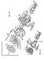
- the wire guide 1 includes an input end 2 and an output end 3. It may be observed that at the output end, the emerging wire holes are in one or more parallel straight rows.
- the wires are arranged in a circular pattern.
- a shoulder 4 integrally molded on wire guide 1 limits the depth of insertion into the hollow sleeve member 14 in its central aperture.
- the frame member and heat sink 8 is a unitary piece comprising the heat sink fin elements 8, integral rigid arms 7 and support rods 9.
- the basic frame body 6 is arranged to make thermal contact with the ends 45 of the cores 17 where they emerge through holes 13 in the flux return member 10.
- Flux return member 10 is formed of silicon iron to provide high magnetic permeability and is provided in a crenellated or castellated form with individual castellations 11 separated from one another by spaces 12 as shown.
- the holes 13 permit the base ends of the magnetic cores 17 to protrude for hot upsetting to lock the cores firmly and in tight magnetic flux path coupling with the flux return member 10.
- the ends of these cores though not shown in Figure 1, may be ground flush with the bottom surface of flux return member 10 so that a tight thermal joint between this member and the heat sink element member body 6 can be achieved.
- a hollow sleeve 14 having a notch 15 is inserted axially through a central aperture in the flux return member and is brazed or silver soldered in place.
- This is a non-magnetic sleeve that is ground to a specific dimension between its ends as will be described later which sets exact tolerances for the assembly of the parts.
- the end surface of sleeve 14 is received within the aperture 5 of the frame element 6.
- the notch 15 in sleeve 14 receives a molded lug on the plastic molded wire guide 1 to orient it relative to the position of the crenellations in the flux return member.
- a shoulder on the wire guide limits the depth of insertion of the wire guide into the sleeve 14 to exactly register the input end of guide 2 at a specified height relative to the top edges of the flux return castellations 11.
- the core members do not appear in this figure but are hot upset and affixed to the flux return member 10 as previously noted.
- the flexible circuit element 18 has two rectangular apertures 19 that fit over individual castellations 11 of the flux return member 10 to precisely locate the windings 17 over the individual core members, not shown.
- a central aperture 20 permits the end 2 of the wire guide 1 to extend through the flexible circuit so that the ends 22 of wires 21 will lie in the vicinity of the end of each individual hammer armature 25 upon assembly.
- Springs 23 are the compression type and are received in small molded seats in the end 2 of the wire guide 1 to resiliently bias the wire 21 back away from the output end 3 of the wire guide 1 and against the ends of the print hammers or armatures 25, thus tending to force the armatures 25 away from the core or pole piece of the electromagnetic windings 17.
- a residual magnetism interrupter 24 is a thin non-magnetic or dielectric plastic material stamped in the shape required to separate the armatures or hammers 25 from direct physical contact with the ends of the castellations 11 of the flux return member 10 or with the central electromagnetic cores of the windings 17. This prevents slight magnetism in the armatures or hammers 25 from retarding the return.
- hammers 25 are pivotally supported on the top edges of the castellations 11 and must be retained in place.
- a means for retaining the hammers will be described with reference also to the backstop element when it is described below.
- the hammers must also be laterally maintained as will now be described.
- a retainer or housing 26 aids in providing this function.
- the retainer or housing 26 comprises a general peripheral wall 29 with a number of webbed fingers 28 joining in a central hub.
- the fingers 28 have generally radial apertures therebetween.
- the radial apertures denoted as 27 are in general form of the profiles of the hammer armatures 25.
- the hammer armatures 25 may be inserted in these apertures 27.
- a thin plastic disk 32 is inserted into the reverse side of the retainer 26 and bears against the central portion of the rubber backstop shock absorber 33 to prevent galling or adhesion between the ends of the hammer armatures 25 and the backstop 33.
- Backstop 33 comprises a unitary, molded, high damping coefficient rubber structure having a number of fingers 35 separated by slots 36 and having peripheral rims or edges 34 slightly upstanding therefrom. These rims or edges 34 are received in a groove in the backside of the retainer 26 where they bear against the ends of the hammer armatures 25 to maintain them lightly in contact with the top surface of the residual magnetism preventer 24. This also maintains a close magnetic coupling flux path with the top edges of the castellations 11 in the flux return member 10.
- the damping rubber backstop member is held in place by a back cover 37 which has a central aperture 38 through which a fastener 43 can be inserted.
- the back cover 37 also has a molded portion that acts as a strain relief cable retainer. This portion is identified as the flange area 39 having a notch 31.
- the notch 31 registers with a molded lug 30 on the periphery of the retainer 26 as shown. This precisely locates the back cover 37 so that the flat wire cable 40 will be maintained in the proper position relative to the portion 18 thereof which joins to the flexible circuit which registers over the flux return member 10 by means of the rectangular apertures 19 as previously described.
- strain relief clamp member 41 is held in place by a load spring 42 and the fastener 43 which is inserted through the aligning set of apertures in the spring, strain relief, cable, back cover, shock absorbing backstop, disk, retainer, residual member, the center of the flexible circuit, the flux return member and finally into a threaded aperture in the center of the wire guide member 1.
- a load spring 42 and the fastener 43 which is inserted through the aligning set of apertures in the spring, strain relief, cable, back cover, shock absorbing backstop, disk, retainer, residual member, the center of the flexible circuit, the flux return member and finally into a threaded aperture in the center of the wire guide member 1.
- the springs 23 are of the helical compression type provide the only return forces to the print wires 21 and to the hammer armatures 25.
- a plastic ferrule tip 22 or head driving means is injection molded onto the end of each wire 21.
- the wires themselves are music wire or similar high tensile steel wires, although carbide-tipped or other hardened wires may be employed as desired.
- the frame body 6 is die cast aluminum for high heat conductivity.
- the integral thin heat sink portion 8 may be made a part of the frame body 6 as in this embodiment.
- Another preferred embodiment utilizes a different form of frame member 6 and the heat sinks are actually integral with the ends of the cores of the electromagnets as will be described later.
- the anti-residual magnetism member 24 is well known to those of skill in the art and prevents the magnetic reluctance path from getting too low and allowing the hammer member to become temporarily magnetized. This insures a quick hammer release once the coil current in the individual coil 17 is turned off and also improves wear at the hammer pivot point where it bears against the top surface of the castellations 11 in the flux return member 10.
- the housing or retainer 26 is molded plastic and locates the hammer armatures 25 in their appropriate relationship. It also controls the air gap between the end of the hammer faces and the top of the electromagnetic cores in the electromagnet 17 by limiting the total displacement backward which can be imparted by the compression springs 23 forcing the ferrules 22 of the individual print wires 21 against the ends of the hammers 25.
- the backstop 33 is inserted in the back side of the housing or retainer 26 sandwiching the anti-galling disk 32 in the process.
- the backstop 33 is molded of a high energy absorbing rubber such as NBR. This backstop absorbs the rebound energy of the hammer 25 after a dot is printed.
- the perimeter 34 has a rib as mentioned earlier that applies force to the end of the hammer armature 25 at the pivot point on the top of the castellations 11 of the flux return member 10. This force is only used to maintain a minimum air gap at the hammer pivot point and provides no return forces to the hammer.
- the back cover 37 is injected molded plastic and serves to insulate the coil connections on circuit 18 from the flux return member 10 by the extension of the wall or flange portion 39 which will extend axially along the area where two or more of the castellations 11 are formed.
- the back cover also provides support for the flexible supply circuit cable 40 and compresses the rubber backstop 33 against the housing or retainer 26.
- the strain relief clamp 41 is also injection molded plastic and protects the flexible circuit element 40 by providing a nest with the flange portion 39 of the back cover 37 as illustrated. It may be understood that the flexible wire circuit 40 is sandwiched between the back cover 37 and the strain relief clamp 41 by means of the fastener 43 compressing the leaf spring 42 upon assembly.
- the compression spring provides resiliency to insure that the assembly remains tight even if the plastic parts tend to creep after assembly.
- Leaf spring 42 also limits the compressive forces in the assembly which provides for precise control of critical dimensions in the assembly.
- FIG. 2 illustrates an alternative embodiment of the frame assembly and flux return member with an improved heat sink structure.
- the frame 6 is provided with a plurality of apertures 46 to receive the projecting finned heat sink elements 47 that extend axially from the ends of the electromagnet cores in the base of the flux return member 10. These heat sink elements may be actually integral with the cores to provide the highest degree of thermal continuity and provide the greatest desired cooling effect.
- the provision of individual finned heat sinks 47 for each core permits free flow of air through the cooling area and greatly enhances the capability of exhausting unwanted heat from the vicinity of the structure.
- FIG 3 illustrates in cross section the details of the flux return member 10, or the yoke assembly as it is sometimes called.
- the flux return member 10 is generally in the form of a flat bottomed cup having upstanding castellation leaves 11 and a central aperture in the bottom through which the sleeve 14 is inserted and brazed or soldered in place.
- the sleeve 14 has castellations of its own in the periphery as shown in 48 to permit the ends of the hammer armatures 25 not shown, to pass freely into the central section of the sleeve 14 and to keep the ends of the armatures or hammers from sliding sideways.
- the castellations are cut deep enough to prevent actual mechanical contact in the impact position of the hammers and it further is made of non-magnetic material to prevent residual magnetism problems in this area. It takes no part in the flux path and thereby provides for a more concentrated flux path between the core members 45 and the flux return castellations 11 in a general U-shape as shown.
- the individual core members 45 are made of silicon iron and are hot upset in apertures 13 located in a circular array in the bottom wall of the cup portion of the flux return member 10 as shown.
- Figure 4 illustrates in plan view the retainer or housing 26 in greater detail. It will be observed that a plurality of generally radial spokes 28 separate the hammer or armature shaped spaces 27. The spokes 28 join the peripheral rim 29 with a central hub as illustrated to provide a uniform and stable part. The molded lug 30 is utilized for registration with the back cover 37 through notch 31 as previously described with reference to Figure 1.
- the thickness of the web spokes 28 in the direction in and out of the plane of the drawing is precisely molded so that, when the individual hammer armatures 25 are inserted in the apertures 27, they will drop to a specified depth and lodge against the molded rubber backstop which is inserted from the backside as a retainer 26.
- the depth of the web sections 28 thus sets the total relative position of the entire nest of hammer armatures 25 relative to the top surface of sleeve 14 as shown in Figure 3 and thereby sets the hammer flight distance for each of the hammers to be identical.
- FIG. 5 illustrates in plan view a greater detail of the molded energy absorbing rubber backstop 33.
- the backstop 33 is a molded rubber part having a plurality of individual leaves or fingers 35 each with an upstanding ridge or peripheral ledge 34 as depicted.
- the ridge 34 is inserted in a groove in the backside of the retainer 26 to bear against the heel ends of the armatures or hammers 25.
- Backstop 33 has a hole or opening in the center to permit the passage of the fastener 43 therethrough.
- Figure 6 illustrates in greater detail a top elevation view of the frame member 6 having integral heat sink fins 8 as shown in the first embodiment of Figure 1.
- the body 6 is joined by integral arms 7 to the support and guide rod 9 which allow insertion of the frame into the printer mechanism.
- the back surface 49 is ground flush for a tight thermal joint, preferably aided by thermally conductive grease or adhesives, with the end surface of the individual electromagnetic core members 45 and the end face of the flux return member 10 upon assembly.
- FIG 7 a partially sectional view of the molded unitary wire guide 1 is illustrated.
- Individual straight channels 50 converge from the original input end 2 to the output surface 3 at opposite ends of the wire guide 1.
- Molded recesses or wells 51 receive the compression spring 23 referred to earlier. It may be observed that while the wire guide channels 50 are generally inclined, they are straight and impose no bending or flexural loads upon the wires when inserted therein. Also, easy insertion of the wires is greatly facilitated.
- a central bore 52 provides seating for the one fastener 43 referred to in Figure 1 for joining the entire assembly as previously discussed.
Landscapes
- Impact Printers (AREA)
Claims (5)
- Verbesserter Nadeldruckerkopf mit:
einer Drahtführung (1) mit einer Mehrzahl von Kanälen zum Führen von Druckerdrähten, wobei die Kanäle eine kreisförmige Anordnung an einem Ende (2) der Führung und eine Austrittsanordnung an dem anderen Ende (3) der Führung bilden,
einem einheitlichen Magnetflußrückkehrteil (10), der wie ein mit Zinnen versehener Becher ausgebildet ist, der eine annähernd kreisförmige Wand mit einem mit Zinnen versehenen Segment und eine kreisförmige ebene Bodenoberfläche mit einer zentralen kreisförmigen Öffnung (20) besitzt, um die Drahtführung aufzunehmen,
einer Mehrzahl von Elektromagneten, die einzelne Magnetkerne (17) mit Wicklungen darauf aufweisen, wobei die Elektromagnete an dem Flußrückkehrteil (10) mit den Kernen befestigt sind, die eine kreisförmige, mit der Wand des Flußrückkehrteiles konzentrische Anordnung bilden,
einem Wärmesenkemittel (6) zum Kühlen der Kerne (17),
einer Mehrzahl von Magnetankern (25), wobei jeder der Magnetanker drehbar an dem oberen Teil eines Abschnitts der Wand des Flußrückkehrteiles (10) auf dessen einem mit Zinnen versehenen Segment getragen ist und sich radial nach innen davon, über einen Kern zu dem Zentrum der kreisförmigen Öffnung (20) hin erstreckt,
einer Mehrzahl von Druckerdrähten (21), die in den Kanälen der Drahtführung (1) aufgenommen sind, wobei jeder Draht ein erweitertes daran angebrachtes Kopfendemittel an dem Ende der Drahtführung mit der kreisförmigen Anordnung aufweist, wobei jeder Anker (25) an ein einzelnes der Kopfendemittel auf einen Draht stoßen,
einem Gegenhaltemittel (33), welches über den Ankern (25) liegt, um deren Rückprallenergie zu absorbieren,
einem Ankerrückhaltemittel (26) zum Halten des Gegenhaltermittels (33) und der Anker (25) in Ausrichtung mit den Kopfendemitteln der Drähte und
einem hinteren Deckmittel (37) und einem Befestigungsmittel (43) zum Halten des Matrixdruckerkopfes in Stellung,
wobei der Nadeldruckerkopf dadurch gekennzeichnet ist, daß das Wärmesenkemittel mit einer äußeren Erweiterung (8) versehen ist, die zur verbesserten Wärmeübertragung gerippt ist,
die Deckmittel an das Rückhaltemittel anstoßen und an den Gegenhalter stoßen, um dessen Kante gegen den oberen Teil der Anker zu halten, wo sie auf dem mit Zinnen versehenen Segment des Flußrückkehrmittels (10) getragen sind,
die Kanäle geradlinig vorgesehen sind,
die Befestigungsmittel (43) durch das hintere Deckmittel (37) in dessen Zentrum geführt und in dem Zentrum der Drahtführung (1) aufgenommen sind und
die Enden (45) die Kerne (17) in der Bodenoberfläche des Flußrückkehrmittels (10) liegen und die hinteren Oberflächen (49) des Wärmesenkemittels (6) ebenfalls in der Bodenfläche liegen, sodaß eine dichte thermische Verbindungsstelle zwischen dem Flußrückkehrmittel und dem Wärmesenkemittel nach dem Montieren des Druckerkopfes erzielt werden kann. - Nadeldruckerkopf nach Anspruch 1, der ferner ein kreisförmiges Hüllrohr (14) aufweist, das in der kreisförmigen Öffnung (20) eingesetzt ist und sich axial dadurch zu dem oberen Teil des Flußrückkehrteiles (10) hin erstreckt und axial von dessen Boden nach außen vorspringt, wobei die Drahtführung (1) in dem Hüllrohr eingesetzt ist und ein darauf geformtes Widerlager aufweist, um die Gesamttiefen des Einsetzens darin zu begrenzen.
- Nadeldruckerkopf nach Anspruch 1 oder 2, bei welchem die Drahtführung (1), das Rückhaltemittel (26) und das Gegenhaltermittel (33) je einheitlich geformt ist.
- Nadeldruckerkopf nach irgendeinem der Ansprüche 1, 2 oder 3, bei welchem die Wärmesenkemittel (6) einen Teil eines Druckerkopfrahmens aufweisen, welcher den Druckerkopf innerhalb eines Druckermechanismus in Lage hält.
- Nadeldruckerkopf nach irgendeinem der Ansprüche 1 bis 4, bei welchem die Gegenhaltermittel (33) in dem Rückhaltemittel (26) von einer Seite aufgenommen sind und die Anker (25) in dem Rückhaltemittel von der anderen Seite aufgenommen sind, wobei die Anker gegen das Gegenhaltermittel anliegen und voneinander durch eine Mehrzahl geformter Speichen in dem Rückhaltemittel getrennt gehalten sind, wobei sich die Speichen an einer zentralen Nabe vereinigen und sich zu einer Umfangsfelge erstrecken.
Applications Claiming Priority (2)
| Application Number | Priority Date | Filing Date | Title |
|---|---|---|---|
| US695339 | 1985-01-28 | ||
| US06/695,339 US4561790A (en) | 1985-01-28 | 1985-01-28 | Wire matrix print head apparatus |
Publications (3)
| Publication Number | Publication Date |
|---|---|
| EP0189792A2 EP0189792A2 (de) | 1986-08-06 |
| EP0189792A3 EP0189792A3 (en) | 1987-08-26 |
| EP0189792B1 true EP0189792B1 (de) | 1991-12-11 |
Family
ID=24792594
Family Applications (1)
| Application Number | Title | Priority Date | Filing Date |
|---|---|---|---|
| EP86100555A Expired EP0189792B1 (de) | 1985-01-28 | 1986-01-17 | Matrixnadeldrucker |
Country Status (5)
| Country | Link |
|---|---|
| US (1) | US4561790A (de) |
| EP (1) | EP0189792B1 (de) |
| JP (1) | JPS61173952A (de) |
| CA (1) | CA1208488A (de) |
| DE (1) | DE3682784D1 (de) |
Families Citing this family (3)
| Publication number | Priority date | Publication date | Assignee | Title |
|---|---|---|---|---|
| US4795283A (en) * | 1986-10-14 | 1989-01-03 | Citizen Watch Co., Ltd. | Print head for a dot-printer |
| DE4242378C2 (de) * | 1992-12-08 | 1996-03-14 | Mannesmann Ag | Matrixdruckkopf der Schlagbauart |
| IT1314814B1 (it) | 2000-05-30 | 2003-01-16 | Compuprint Spa | Testina di stampa ad aghi |
Family Cites Families (13)
| Publication number | Priority date | Publication date | Assignee | Title |
|---|---|---|---|---|
| US3896918A (en) * | 1971-03-04 | 1975-07-29 | Winfried Schneider | Mosaic printing head with electromagnetically actuated needles with a common yoke for all electromagnets |
| DE2201049C3 (de) * | 1972-01-11 | 1978-04-06 | Winfried 4794 Schloss Neuhaus Schneider | Mosaikdruckkopf |
| US3770092A (en) * | 1972-02-14 | 1973-11-06 | Autotronics Inc | Wire print head |
| DE2342420A1 (de) * | 1973-08-22 | 1975-03-13 | Steinmetz Krischke Systemtech | Mosaikdruckknopf |
| US3893220A (en) * | 1974-08-01 | 1975-07-08 | Gen Electric | Method of making wire matrix print head nozzle |
| US3929214A (en) * | 1974-09-18 | 1975-12-30 | D & D Ass | Wire matrix ballistic impact print head |
| US4443122A (en) * | 1979-05-14 | 1984-04-17 | Blomquist James E | Dot matrix print head |
| US4401392A (en) * | 1979-05-14 | 1983-08-30 | Blomquist James E | Dot matrix print head |
| US4375338A (en) * | 1979-07-16 | 1983-03-01 | Kabushiki Kaisha Suwa Seikosha | Wire dot print head |
| JPS5772871A (en) * | 1980-10-25 | 1982-05-07 | Brother Ind Ltd | Printing head of dot printer |
| DE3149300A1 (de) * | 1981-12-12 | 1983-06-23 | Kienzle Apparate Gmbh, 7730 Villingen-Schwenningen | Nadeldrucksystem mit montageguenstigem aufbau und verfahren zur herstellung desselben |
| IT1156203B (it) * | 1982-10-12 | 1987-01-28 | Olivetti & Co Spa | Testina di stampa a fili di tipo balistico |
| US4502799A (en) * | 1983-02-25 | 1985-03-05 | Ncr Corporation | Dot matrix print head |
-
1985
- 1985-01-28 US US06/695,339 patent/US4561790A/en not_active Expired - Lifetime
- 1985-06-07 CA CA000483513A patent/CA1208488A/en not_active Expired
- 1985-10-15 JP JP60227942A patent/JPS61173952A/ja active Pending
-
1986
- 1986-01-17 DE DE8686100555T patent/DE3682784D1/de not_active Expired - Lifetime
- 1986-01-17 EP EP86100555A patent/EP0189792B1/de not_active Expired
Also Published As
| Publication number | Publication date |
|---|---|
| EP0189792A2 (de) | 1986-08-06 |
| JPS61173952A (ja) | 1986-08-05 |
| CA1208488A (en) | 1986-07-29 |
| US4561790A (en) | 1985-12-31 |
| EP0189792A3 (en) | 1987-08-26 |
| DE3682784D1 (de) | 1992-01-23 |
Similar Documents
| Publication | Publication Date | Title |
|---|---|---|
| US5434549A (en) | Moving magnet-type actuator | |
| US11087942B2 (en) | Electromagnetic relay and a method of making the same | |
| US4561790A (en) | Wire matrix print head apparatus | |
| JPS6050330B2 (ja) | ソレノイド | |
| US4730176A (en) | Electromagnet having a pivoted polarized armature | |
| JP3679507B2 (ja) | ワイヤドットプリンタヘッド | |
| US6731191B2 (en) | DC electromagnet | |
| US4737042A (en) | Printing head with springs for pivotably holding printing hammers | |
| EP0418268B1 (de) | Punktmatrizen-druckkopfzusammenbau | |
| US4389128A (en) | Print head for a dot matrix printer | |
| GB2252752A (en) | Armature pivots in dot-matrix printers | |
| US4177441A (en) | Electromagnetic structure for a vital relay | |
| US4567457A (en) | Electromagnetic relay | |
| US5163761A (en) | Dot print head | |
| JPH0519469B2 (de) | ||
| JPH0345816Y2 (de) | ||
| US4682903A (en) | Thin line printer typing head | |
| KR930004840B1 (ko) | 도트프린터 헤드 | |
| JPH043911B2 (de) | ||
| US20060066424A1 (en) | Electromagnetic relay | |
| JPS6212616Y2 (de) | ||
| JPS62287606A (ja) | 交流電磁石 | |
| JPH0327795Y2 (de) | ||
| JPH0316192Y2 (de) | ||
| US4929101A (en) | Release-type dot print head |
Legal Events
| Date | Code | Title | Description |
|---|---|---|---|
| PUAI | Public reference made under article 153(3) epc to a published international application that has entered the european phase |
Free format text: ORIGINAL CODE: 0009012 |
|
| AK | Designated contracting states |
Kind code of ref document: A2 Designated state(s): DE FR GB IT |
|
| 17P | Request for examination filed |
Effective date: 19861125 |
|
| PUAL | Search report despatched |
Free format text: ORIGINAL CODE: 0009013 |
|
| AK | Designated contracting states |
Kind code of ref document: A3 Designated state(s): DE FR GB IT |
|
| 17Q | First examination report despatched |
Effective date: 19890209 |
|
| GRAA | (expected) grant |
Free format text: ORIGINAL CODE: 0009210 |
|
| AK | Designated contracting states |
Kind code of ref document: B1 Designated state(s): DE FR GB IT |
|
| REF | Corresponds to: |
Ref document number: 3682784 Country of ref document: DE Date of ref document: 19920123 |
|
| ET | Fr: translation filed | ||
| ITF | It: translation for a ep patent filed | ||
| PLBE | No opposition filed within time limit |
Free format text: ORIGINAL CODE: 0009261 |
|
| STAA | Information on the status of an ep patent application or granted ep patent |
Free format text: STATUS: NO OPPOSITION FILED WITHIN TIME LIMIT |
|
| 26N | No opposition filed | ||
| PGFP | Annual fee paid to national office [announced via postgrant information from national office to epo] |
Ref country code: GB Payment date: 19961220 Year of fee payment: 12 |
|
| PGFP | Annual fee paid to national office [announced via postgrant information from national office to epo] |
Ref country code: FR Payment date: 19970120 Year of fee payment: 12 |
|
| PGFP | Annual fee paid to national office [announced via postgrant information from national office to epo] |
Ref country code: DE Payment date: 19970128 Year of fee payment: 12 |
|
| PG25 | Lapsed in a contracting state [announced via postgrant information from national office to epo] |
Ref country code: GB Free format text: LAPSE BECAUSE OF NON-PAYMENT OF DUE FEES Effective date: 19980117 |
|
| PG25 | Lapsed in a contracting state [announced via postgrant information from national office to epo] |
Ref country code: FR Free format text: THE PATENT HAS BEEN ANNULLED BY A DECISION OF A NATIONAL AUTHORITY Effective date: 19980131 |
|
| GBPC | Gb: european patent ceased through non-payment of renewal fee |
Effective date: 19980117 |
|
| PG25 | Lapsed in a contracting state [announced via postgrant information from national office to epo] |
Ref country code: DE Free format text: LAPSE BECAUSE OF NON-PAYMENT OF DUE FEES Effective date: 19981001 |
|
| REG | Reference to a national code |
Ref country code: FR Ref legal event code: ST |
|
| PG25 | Lapsed in a contracting state [announced via postgrant information from national office to epo] |
Ref country code: IT Free format text: LAPSE BECAUSE OF NON-PAYMENT OF DUE FEES Effective date: 20050117 |