EP0189860B1 - Méthode de correction d'erreurs d'image - Google Patents
Méthode de correction d'erreurs d'image Download PDFInfo
- Publication number
- EP0189860B1 EP0189860B1 EP86100924A EP86100924A EP0189860B1 EP 0189860 B1 EP0189860 B1 EP 0189860B1 EP 86100924 A EP86100924 A EP 86100924A EP 86100924 A EP86100924 A EP 86100924A EP 0189860 B1 EP0189860 B1 EP 0189860B1
- Authority
- EP
- European Patent Office
- Prior art keywords
- signal values
- picture
- dpcm
- television
- picture signal
- Prior art date
- Legal status (The legal status is an assumption and is not a legal conclusion. Google has not performed a legal analysis and makes no representation as to the accuracy of the status listed.)
- Expired - Lifetime
Links
- 238000000034 method Methods 0.000 title claims abstract description 26
- 238000012916 structural analysis Methods 0.000 claims abstract 2
- 238000012937 correction Methods 0.000 claims description 18
- 230000015654 memory Effects 0.000 description 22
- 238000001514 detection method Methods 0.000 description 17
- 230000005540 biological transmission Effects 0.000 description 9
- 238000010586 diagram Methods 0.000 description 3
- 238000012545 processing Methods 0.000 description 3
- 230000009467 reduction Effects 0.000 description 2
- 238000006243 chemical reaction Methods 0.000 description 1
- 230000007423 decrease Effects 0.000 description 1
- 238000011156 evaluation Methods 0.000 description 1
- 230000006870 function Effects 0.000 description 1
- 230000010354 integration Effects 0.000 description 1
- 230000000873 masking effect Effects 0.000 description 1
Images

Classifications
-
- H—ELECTRICITY
- H04—ELECTRIC COMMUNICATION TECHNIQUE
- H04N—PICTORIAL COMMUNICATION, e.g. TELEVISION
- H04N19/00—Methods or arrangements for coding, decoding, compressing or decompressing digital video signals
- H04N19/85—Methods or arrangements for coding, decoding, compressing or decompressing digital video signals using pre-processing or post-processing specially adapted for video compression
- H04N19/89—Methods or arrangements for coding, decoding, compressing or decompressing digital video signals using pre-processing or post-processing specially adapted for video compression involving methods or arrangements for detection of transmission errors at the decoder
- H04N19/895—Methods or arrangements for coding, decoding, compressing or decompressing digital video signals using pre-processing or post-processing specially adapted for video compression involving methods or arrangements for detection of transmission errors at the decoder in combination with error concealment
-
- H—ELECTRICITY
- H04—ELECTRIC COMMUNICATION TECHNIQUE
- H04N—PICTORIAL COMMUNICATION, e.g. TELEVISION
- H04N19/00—Methods or arrangements for coding, decoding, compressing or decompressing digital video signals
- H04N19/50—Methods or arrangements for coding, decoding, compressing or decompressing digital video signals using predictive coding
Definitions
- the invention relates to a method for correcting image errors in the transmission of DPCM-coded image signals.
- the first method uses error-correcting codes to reduce transmission errors. However, these require a share of over 5% of the transmission capacity.
- image error masking is used. For this purpose, a transmission error only has to be recognized and the disturbed image signal values are replaced by the correction values which were taken from a previous television image or which are obtained from the surrounding image signal values by interpolation.
- the third option is a line-by-line correction. Error detection is carried out using parity bits. However, this principle can only be introduced in a correspondingly modified transmission method. The disturbed lines are completely replaced by buffered lines of a previous image or values of the same field obtained by interpolation. A correction is also made line by line. Buffered image signal values can be used in still image parts, but correction values obtained in moving image parts by interpolation of adjacent image signal values.
- This article does not give any indication that error tracking is carried out with multidimensional prediction and that a better image can be achieved by correcting disturbed image signals.
- the invention is based on the knowledge that, depending on the prediction algorithm in the event of a transmission error, the error trail generated has a certain geometric structure, the size of the errors of the individual image signal values also being determined by the prediction algorithm.
- the typical error structure is determined on the basis of a comparison with the television picture last received. In the case of the excessive field method, the comparison can be carried out with the corresponding field of the last television picture or — with slight reductions — a comparison can also be carried out with the last field received. If a disturbance is detected, the disturbed image signal values are replaced by the temporarily stored image signal values. Correction values can be used, especially in the field method, which were obtained by interpolating the image signal values of two successive lines and buffered.
- the error tow detection and correction can of course also be carried out before the conversion back to PCM signal values, which is not the same as an integration method described by the prediction algorithm, by comparing the DPCM signal values and by correcting the disturbed DPCM signal value. This method requires less circuitry.
- FIG. 1 shows a detail from a television picture.
- the individual crosses x and letters each correspond to an image signal value.
- the encoding is used to convert the signal values surrounding a current image signal value X, here A, B, C, and D, into a predictive value determined, which is compared with the current image signal value X. The difference is then sent out as DPCM signal value As.
- the PCM signal values are again determined from the already reconstructed signal values A r , B " C r and D r and the corresponding DPCM signal value ⁇ s by a corresponding procedure.
- an error loop Z1 occurs, the limits of which in the prediction algorithm specified above - as seen from the disturbed signal value Y - horizontally towards the end of the line and approximately diagonally to the left under.
- a clearly visible core zone Z1 with severely disturbed image signal values runs from the first disturbed image signal value Y approximately diagonally to the bottom right.
- the intensity of the interference generally decreases rapidly with the removal from the first disturbed image signal value. If only positive factors a, b, c and d are used in the prediction, the errors in the image signal values are also rectified, i.e. all pixels affected by the disturbance are uniformly lighter or darker.
- the corrected device shown in FIG. 3 is supplied with the reconstructed image signal values Sr (PCM values) via an input 1.
- the first input 61 of an error tow detection 6 is connected directly to the input 1, while a second input 62 of the error tow detection is connected to the input 1 via an image memory 2.
- the input 1 is also connected via a first runtime memory 3 to an input of a switch 5, at the output 8 of which the corrected image signal values S c are output.
- the output of the image memory is also connected to the second input of the switch 5 via a second delay memory 4, which has the same delay ⁇ ⁇ as the first delay memory 3.
- the changeover switch 5 is controlled via a control output 63 of the error tow detection 6.
- the image memory 2 has the running time of a complete television picture.
- the mutually corresponding image signal values of two successive television images are thus present at the two inputs 61 and 62 of the error tow detection. Since the geometric structure of the error train is known due to the prediction method used, the error train detection 6 can easily identify faults. In order to avoid wrong decisions, the image signal values not affected by a disturbance are also evaluated in order to avoid the pretense of an error train due to a change in the image motif. However, if an error trail has been reliably detected, the changeover switch is switched from the position shown in FIG. 3 to the output of the second runtime memory 4. As a result, the disturbed image signal values are replaced by the undisturbed image signal values of the previous television picture.
- the running time of the runtime memories 3 and 4 corresponds to the processing time of the error tow detection 6.
- the error tow detection 6 can replace the disturbed image signal values, only the disturbed image signal values of the core zone Z1 or entire television lines up to the entire television image or television field.
- the air time of the image memory 2 corresponds to the duration of a television field, since in general the image signal values of successive television lines differ only slightly from one another.
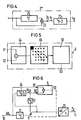
- An improvement in the image quality is achieved by interpolation, in a particularly simple case by using an image memory 2 * shown in FIG. 4.
- This image memory contains a delay element 21, which has the delay T2 of a television line.
- the input and output of this delay element are connected via an adder to the input of a further delay element 23, the delay time TB - 2 of which corresponds to the duration of a television picture except for one television line.
- the first runtime memory 3 is expediently designed as part of the image memory 2.
- it is useful in place of undisturbed as faulty recognized image signal values correction values-that is, the previously stored image signal values S st -er- neut into the frame memory to be written.
- the error tow detection will first be explained in more detail. Realizing them is far less difficult for a person skilled in the art than other problems of object or character recognition, since the geometric structure of the error train is known due to the selected prediction method, all disturbances are directed in the same way and the relationship between the error quantities of the different image signal values is also known.
- a subtraction circuit 64 contains a subtraction circuit 64 with inputs 61 and 62.
- a structure analysis circuit 65 is connected to the output of subtraction circuit 64, which essentially consists of memories for several television lines.
- An evaluation and control logic 66 is connected to the output of the structure analysis circuit and actuates the changeover switch 5 in FIG. 3 via the control output 63.
- FIG. 6 shows a correction device to which DPCM signal values As are supplied and which replaces the disturbed DPCM signal values with undisturbed, temporarily stored DPCM signal values.
- the input 10 of this correction device is connected directly to a first input 91 of an error detection 9 and is connected to a second input 92 of the error detection 9 via a delay element 31, a changeover switch 5 and an image memory 24.
- the output of the image memory 24 is also via a delay element 41 with a second input of the switch 5, at the output of which a DPCM decoder 10 is connected, at the output 11 of which the corrected image signal values Sc are output.
- the changeover switch 5 is actuated via the control output 93 of the error detection 9.
- the function of the correction arrangement shown in FIG. 6 largely corresponds to the correction arrangement according to FIG. 3.
- the DPCM signal values As of successive television images or television fields are compared directly with one another, and if a disturbed DPCM signal value is determined, this is replaced by a buffered correction value from the image memory 24 replaced.
- the term i 3 the delay elements 31 and 41 in turn corresponds to the processing time of the error detecting 9.
- DPCM signal value .DELTA.S st again through the changeover switch 5 in the image memory 24 is written.
- the runtime TB - 3 (or storage capacity) of the image memory 24 corresponds to the duration of a television picture or that of a television field except for the runtime T3 .
- the error detection is even easier to implement than the error tow detection. If there is a single deviation in the DPCM values of two successive television pictures or television fields with the adjacent DPCM signal values remaining the same, a transmission error can be assumed with great certainty and a correction can be made by using the corresponding cached DPCM value. As adjacent DPCM signal values, the signal value following the disturbed DPCM value y and the DPCM signal value below y should also be checked.
- the DPCM values can also be interpolated and buffered in accordance with the interpolation for image signal values.
- the DPCM signal values represent a derivative of the image signal values to a certain extent.
- the DPCM signal values or the image signal values will be corrected.
Landscapes
- Engineering & Computer Science (AREA)
- Multimedia (AREA)
- Signal Processing (AREA)
- Compression Or Coding Systems Of Tv Signals (AREA)
- Error Detection And Correction (AREA)
- Compression, Expansion, Code Conversion, And Decoders (AREA)
- Television Systems (AREA)
- Processing Or Creating Images (AREA)
- Two-Way Televisions, Distribution Of Moving Picture Or The Like (AREA)
- Measuring And Recording Apparatus For Diagnosis (AREA)
Claims (9)
Priority Applications (1)
| Application Number | Priority Date | Filing Date | Title |
|---|---|---|---|
| AT86100924T ATE53732T1 (de) | 1985-01-24 | 1986-01-23 | Verfahren zur bildfehlerkorrektur. |
Applications Claiming Priority (2)
| Application Number | Priority Date | Filing Date | Title |
|---|---|---|---|
| DE3502317 | 1985-01-24 | ||
| DE19853502317 DE3502317A1 (de) | 1985-01-24 | 1985-01-24 | Verfahren zur bildfehlerkorrektur |
Publications (2)
| Publication Number | Publication Date |
|---|---|
| EP0189860A1 EP0189860A1 (fr) | 1986-08-06 |
| EP0189860B1 true EP0189860B1 (fr) | 1990-06-13 |
Family
ID=6260656
Family Applications (1)
| Application Number | Title | Priority Date | Filing Date |
|---|---|---|---|
| EP86100924A Expired - Lifetime EP0189860B1 (fr) | 1985-01-24 | 1986-01-23 | Méthode de correction d'erreurs d'image |
Country Status (7)
| Country | Link |
|---|---|
| US (1) | US4914745A (fr) |
| EP (1) | EP0189860B1 (fr) |
| JP (1) | JPS61171288A (fr) |
| AT (1) | ATE53732T1 (fr) |
| AU (1) | AU569650B2 (fr) |
| CA (1) | CA1280507C (fr) |
| DE (2) | DE3502317A1 (fr) |
Families Citing this family (7)
| Publication number | Priority date | Publication date | Assignee | Title |
|---|---|---|---|---|
| DE3502315A1 (de) * | 1985-01-24 | 1986-07-24 | Siemens AG, 1000 Berlin und 8000 München | Verfahren zur bildfehlerkorrektur |
| EP0232417B1 (fr) * | 1985-10-02 | 1991-11-06 | Deutsche Thomson-Brandt GmbH | Procede pour corriger les erreurs de transmission |
| DE3939136A1 (de) * | 1989-11-27 | 1991-05-29 | Daimler Benz Ag | Verfahren zur decodierung von codierten bilddaten |
| GB2250395A (en) * | 1990-11-27 | 1992-06-03 | Ferguson Ltd | Reducing visibility of impulsive interference in television satellite recievers |
| US5617333A (en) * | 1993-11-29 | 1997-04-01 | Kokusai Electric Co., Ltd. | Method and apparatus for transmission of image data |
| DE19524808A1 (de) * | 1995-07-07 | 1997-01-09 | Thomson Brandt Gmbh | Verfahren, Encoder und Decoder zur Resynchronisierung auf einen fehlerbehafteten Datenstrom |
| US6985174B1 (en) * | 2001-10-30 | 2006-01-10 | Logitech Europe S.A. | Dynamic radio frequency interference detection and correction |
Family Cites Families (6)
| Publication number | Priority date | Publication date | Assignee | Title |
|---|---|---|---|---|
| US4403250A (en) * | 1980-03-18 | 1983-09-06 | Micro Consultants Limited | Processing of T.V. pictures for subsequent stop mode reproduction |
| DE3311911A1 (de) * | 1983-03-31 | 1984-10-04 | Siemens AG, 1000 Berlin und 8000 München | Verfahren und schaltungsanordnung zur bildfehlerkorrektur |
| KR910009880B1 (ko) * | 1983-07-25 | 1991-12-03 | 가부시기가이샤 히다찌세이사꾸쇼 | 인터레이스된 텔레비젼 신호중의 화상의 움직임 검출회로 |
| DE3331426A1 (de) * | 1983-08-31 | 1985-03-14 | Siemens AG, 1000 Berlin und 8000 München | Anordnung zur zweidimensionalen dpcm-codierung |
| DE3333404A1 (de) * | 1983-09-15 | 1985-04-04 | Siemens AG, 1000 Berlin und 8000 München | Verfahren und schaltungsanordnung zur verbesserung der bildqualitaet durch aktivitaetsgesteuerte dpcm-codierung |
| US4651211A (en) * | 1986-01-17 | 1987-03-17 | Rca Corporation | Video signal motion detecting apparatus |
-
1985
- 1985-01-24 DE DE19853502317 patent/DE3502317A1/de not_active Withdrawn
-
1986
- 1986-01-22 CA CA000500100A patent/CA1280507C/fr not_active Expired - Lifetime
- 1986-01-23 AU AU52641/86A patent/AU569650B2/en not_active Ceased
- 1986-01-23 DE DE8686100924T patent/DE3672070D1/de not_active Expired - Lifetime
- 1986-01-23 AT AT86100924T patent/ATE53732T1/de not_active IP Right Cessation
- 1986-01-23 EP EP86100924A patent/EP0189860B1/fr not_active Expired - Lifetime
- 1986-01-24 JP JP61012238A patent/JPS61171288A/ja active Pending
-
1988
- 1988-07-12 US US07/218,582 patent/US4914745A/en not_active Expired - Fee Related
Also Published As
| Publication number | Publication date |
|---|---|
| CA1280507C (fr) | 1991-02-19 |
| EP0189860A1 (fr) | 1986-08-06 |
| DE3502317A1 (de) | 1986-07-24 |
| AU5264186A (en) | 1986-07-31 |
| ATE53732T1 (de) | 1990-06-15 |
| AU569650B2 (en) | 1988-02-11 |
| DE3672070D1 (de) | 1990-07-19 |
| JPS61171288A (ja) | 1986-08-01 |
| US4914745A (en) | 1990-04-03 |
Similar Documents
| Publication | Publication Date | Title |
|---|---|---|
| DE3222648C2 (de) | Anpassungsfähige Inter-Frame-Prädiktionseinrichtung für Fernsehsignale | |
| DE3021033C2 (de) | Verfahren zur bewegungskompensierten Zwischen-Halbbild-Kodierung | |
| DE3121599C2 (de) | Verfahren und Schaltungsanordnung zum Verdecken von Fehlern in einem digitalen Videosignal | |
| DE69323156T2 (de) | Bilddatenkomprimierungs/Dekomprimierungssystem | |
| DE69022461T2 (de) | Bildbewegungsvektordetektor. | |
| DE69126804T2 (de) | Kompressionssystem von bewegten Bilddaten | |
| DE69123705T2 (de) | Verfahren zur Kompression von bewegten Bildsignalen nach dem Zeilensprungverfahren | |
| DE69226344T2 (de) | Dekodiersystem für Bewegtbilder | |
| DE3688343T2 (de) | Bewegungskompensierter praediktiver codierer fuer ein signal eines sich bewegenden bildes mit reduzierter informationsmenge. | |
| EP0276753B1 (fr) | Méthode et appareil pour la transmission d'informations numériques et/ou l' enregistrement et la reproduction | |
| DE3429901C2 (de) | Verfahren und anordnung zur uebertragung von daten | |
| DE3742098A1 (de) | Verfahren und vorrichtung zur kompression und rekonstruktion von daten | |
| DE3629472A1 (de) | Verfahren zur bewegungskompensierten bild-zu-bild-praediktionscodierung | |
| EP0123893B1 (fr) | Procédé et circuit pour la correction des erreurs d'image | |
| DE3331426A1 (de) | Anordnung zur zweidimensionalen dpcm-codierung | |
| DE69024002T2 (de) | Vorrichtung zum Codieren von zweidimensionalen Informationen und entsprechende Decodiervorrichtung. | |
| DE69232215T2 (de) | Einrichtung zur Bildkodierung | |
| DE69515535T2 (de) | Verfahren und Vorrichtung zum Bildvergleich | |
| EP0189860B1 (fr) | Méthode de correction d'erreurs d'image | |
| DE3117206A1 (de) | Verfahren und schaltungsanordnung zum verdecken von fehlern in einem digitalen farbvideosignal | |
| EP0414016B1 (fr) | Procédé pour former les images de prédiction | |
| DE69124823T2 (de) | Verarbeitung von Bildsignalen | |
| DE69515755T2 (de) | Vorrichtung zur Detektion von Bewegungsvektoren | |
| EP0189859B1 (fr) | Méthode de correction d'erreurs d'image | |
| DE3311898C2 (de) | Verfahren zur Störsignalreduktion von digitalen datenreduzierten Fernsehsignalen |
Legal Events
| Date | Code | Title | Description |
|---|---|---|---|
| PUAI | Public reference made under article 153(3) epc to a published international application that has entered the european phase |
Free format text: ORIGINAL CODE: 0009012 |
|
| AK | Designated contracting states |
Kind code of ref document: A1 Designated state(s): AT BE CH DE FR GB IT LI NL SE |
|
| 17P | Request for examination filed |
Effective date: 19860923 |
|
| 17Q | First examination report despatched |
Effective date: 19880817 |
|
| GRAA | (expected) grant |
Free format text: ORIGINAL CODE: 0009210 |
|
| AK | Designated contracting states |
Kind code of ref document: B1 Designated state(s): AT BE CH DE FR GB IT LI NL SE |
|
| REF | Corresponds to: |
Ref document number: 53732 Country of ref document: AT Date of ref document: 19900615 Kind code of ref document: T |
|
| REF | Corresponds to: |
Ref document number: 3672070 Country of ref document: DE Date of ref document: 19900719 |
|
| ET | Fr: translation filed | ||
| ITF | It: translation for a ep patent filed | ||
| GBT | Gb: translation of ep patent filed (gb section 77(6)(a)/1977) | ||
| PGFP | Annual fee paid to national office [announced via postgrant information from national office to epo] |
Ref country code: GB Payment date: 19901217 Year of fee payment: 6 |
|
| PGFP | Annual fee paid to national office [announced via postgrant information from national office to epo] |
Ref country code: AT Payment date: 19901219 Year of fee payment: 6 |
|
| PGFP | Annual fee paid to national office [announced via postgrant information from national office to epo] |
Ref country code: FR Payment date: 19910121 Year of fee payment: 6 |
|
| PGFP | Annual fee paid to national office [announced via postgrant information from national office to epo] |
Ref country code: BE Payment date: 19910124 Year of fee payment: 6 |
|
| PGFP | Annual fee paid to national office [announced via postgrant information from national office to epo] |
Ref country code: SE Payment date: 19910125 Year of fee payment: 6 |
|
| ITTA | It: last paid annual fee | ||
| PG25 | Lapsed in a contracting state [announced via postgrant information from national office to epo] |
Ref country code: LI Effective date: 19910131 Ref country code: CH Effective date: 19910131 |
|
| PGFP | Annual fee paid to national office [announced via postgrant information from national office to epo] |
Ref country code: NL Payment date: 19910131 Year of fee payment: 6 |
|
| PLBE | No opposition filed within time limit |
Free format text: ORIGINAL CODE: 0009261 |
|
| STAA | Information on the status of an ep patent application or granted ep patent |
Free format text: STATUS: NO OPPOSITION FILED WITHIN TIME LIMIT |
|
| 26N | No opposition filed | ||
| REG | Reference to a national code |
Ref country code: CH Ref legal event code: PL |
|
| PG25 | Lapsed in a contracting state [announced via postgrant information from national office to epo] |
Ref country code: DE Effective date: 19911001 |
|
| PG25 | Lapsed in a contracting state [announced via postgrant information from national office to epo] |
Ref country code: GB Effective date: 19920123 Ref country code: AT Effective date: 19920123 |
|
| PG25 | Lapsed in a contracting state [announced via postgrant information from national office to epo] |
Ref country code: SE Effective date: 19920124 |
|
| PG25 | Lapsed in a contracting state [announced via postgrant information from national office to epo] |
Ref country code: BE Effective date: 19920131 |
|
| BERE | Be: lapsed |
Owner name: SIEMENS A.G. Effective date: 19920131 |
|
| PG25 | Lapsed in a contracting state [announced via postgrant information from national office to epo] |
Ref country code: NL Effective date: 19920801 |
|
| NLV4 | Nl: lapsed or anulled due to non-payment of the annual fee | ||
| REG | Reference to a national code |
Ref country code: GB Ref legal event code: PCNP |
|
| PG25 | Lapsed in a contracting state [announced via postgrant information from national office to epo] |
Ref country code: FR Effective date: 19920930 |
|
| REG | Reference to a national code |
Ref country code: FR Ref legal event code: ST |
|
| EUG | Se: european patent has lapsed |
Ref document number: 86100924.9 Effective date: 19920806 |
|
| PG25 | Lapsed in a contracting state [announced via postgrant information from national office to epo] |
Ref country code: IT Free format text: LAPSE BECAUSE OF NON-PAYMENT OF DUE FEES Effective date: 20050123 |