EP0189863A2 - Soupape d'injection pour moteurs à combustion interne à compression du mélange - Google Patents
Soupape d'injection pour moteurs à combustion interne à compression du mélange Download PDFInfo
- Publication number
- EP0189863A2 EP0189863A2 EP86100945A EP86100945A EP0189863A2 EP 0189863 A2 EP0189863 A2 EP 0189863A2 EP 86100945 A EP86100945 A EP 86100945A EP 86100945 A EP86100945 A EP 86100945A EP 0189863 A2 EP0189863 A2 EP 0189863A2
- Authority
- EP
- European Patent Office
- Prior art keywords
- injection valve
- sealing ring
- sleeve
- injection
- internal combustion
- Prior art date
- Legal status (The legal status is an assumption and is not a legal conclusion. Google has not performed a legal analysis and makes no representation as to the accuracy of the status listed.)
- Granted
Links
Images
Classifications
-
- F—MECHANICAL ENGINEERING; LIGHTING; HEATING; WEAPONS; BLASTING
- F02—COMBUSTION ENGINES; HOT-GAS OR COMBUSTION-PRODUCT ENGINE PLANTS
- F02M—SUPPLYING COMBUSTION ENGINES IN GENERAL WITH COMBUSTIBLE MIXTURES OR CONSTITUENTS THEREOF
- F02M61/00—Fuel-injectors not provided for in groups F02M39/00 - F02M57/00 or F02M67/00
- F02M61/14—Arrangements of injectors with respect to engines; Mounting of injectors
- F02M61/145—Arrangements of injectors with respect to engines; Mounting of injectors the injection nozzle opening into the air intake conduit
-
- Y—GENERAL TAGGING OF NEW TECHNOLOGICAL DEVELOPMENTS; GENERAL TAGGING OF CROSS-SECTIONAL TECHNOLOGIES SPANNING OVER SEVERAL SECTIONS OF THE IPC; TECHNICAL SUBJECTS COVERED BY FORMER USPC CROSS-REFERENCE ART COLLECTIONS [XRACs] AND DIGESTS
- Y10—TECHNICAL SUBJECTS COVERED BY FORMER USPC
- Y10S—TECHNICAL SUBJECTS COVERED BY FORMER USPC CROSS-REFERENCE ART COLLECTIONS [XRACs] AND DIGESTS
- Y10S251/00—Valves and valve actuation
- Y10S251/90—Valves with o-rings
Definitions
- the invention relates to an injection valve of the type specified in the preamble of the first claim.
- the O-ring arranged on the mouthpiece of the injection valve is pressed radially when inserted into the receiving bore in the intake manifold wall.
- the receiving bore usually has a chamfer on the plug-in side, by means of which the pressing of the O-ring is initiated when it is inserted into the receiving bore.
- this chamfer is generally relatively low in the area around the receiving bore in the insertion direction and is formed at a relatively large cone angle. This results in a relatively sharp edge at the transition from the receiving bore into the chamfer, which can lead to damage to the O-ring if the mouthpiece of the injection nozzle is positioned off-center to the receiving bore.
- a plug arrangement with an interposed sealing ring is provided for decoupling the noise between the injection valves and the fuel distributor line, similar to the above-described intake manifold-side plug arrangement.
- each injection valve can be moved to a certain extent relative to the fuel distributor line, so that when the injection valves are installed at the same time, some have eccentric positions Injectors are to be expected in their mounting holes.
- the object of the present invention is to develop an injection valve of the generic type in such a way that damage to the sealing ring during assembly is excluded.
- the sealing ring is protected both in the time after the injection valve has been completed and until it is installed, and also during installation. The displacement of the sleeve and thus the release of the sealing ring is only achieved when the injector is installed.
- the development according to claim 2 describes an advantageous inner contour of the sleeve. This ensures that the sealing ring slides easily and without damage into the mounting hole when the injection valve is installed. On the other hand, this does not hinder the insertion of the injection valve.
- Another development of the invention according to claim 3 has the advantage that, without further aids, both a secure axial displacement of the sleeve is made possible and a secure hold in the time in which the sleeve is not installed is. In particular, no further aids such as adhesive strips, clips, etc. are required to use the sleeve as protection for the sealing ring until the injection valve is installed.
- the sleeve simultaneously takes over a centering function, so that the attachment of the injection valve, in particular if a plurality of injection valves are to be installed simultaneously, is greatly facilitated.
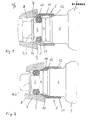
- FIG. 1 the front part of an injection valve 1 for a mixture-compressing internal combustion engine, not shown, is shown schematically. It carries on its front mouthpiece 2 a sealing ring 3, which is preferably designed as an O-ring. This is supported in the axial direction on a shoulder 4 and 4.1. The sealing ring 3 is enclosed by a sleeve 5 which is guided on a cylindrical section 6 of the injection valve 1.
- the injection valve 1 is inserted with its mouthpiece 2 into a wall opening 8 of the suction pipe 7, the mounting of the injection valve 1 essentially through the pressed sealing ring 3 between the wall opening 8 and the mouthpiece 2 is achieved.
- the wall opening or receiving bore 8 has a chamfer 9 on the insertion side.
- the sleeve 5 provided according to the invention has at its front end a conical outer contour 10 which merges into a cylindrical section 11.
- the cone angle is equal to twice the chamfer angle, so that the sleeve 5 can be used simultaneously for centering the injection valve 1 during the insertion process.
- the inner contour of the sleeve 5 consists of three sections, two cylindrical sections 12 and 13 and a conical section 14 being provided.
- the diameter of the cylindrical inner section 12 corresponds in diameter to the outer diameter of the cylindrical section 6 of the injection valve 1.
- the second cylindrical section 13 is smaller in diameter than the section 12. Its diameter corresponds approximately to the outer diameter of the sealing ring 3. However, it is slightly smaller, so that the sleeve 5 is securely held by the sealing ring 3 in the unassembled state and protects it against damage and contamination.
- the transition between the two cylindrical sections 12 and 13 is preferably crowned. This makes it easier to push the sleeve onto the injection valve.
- the smallest diameter of the cone is slightly smaller than the inside diameter of the wall opening 8. This ensures that the sealing ring 3 does not come into contact with the inner edge of the chamfer 9 when the injection valve 1 is inserted and is thereby damaged.
- the injector 1 is shown in its installed position.
- the injection valve 1 is displaced axially under slight pressure.
- the sealing ring 3 is squeezed by the conical section 14 while simultaneously axially pushing forward through the shoulder 4 into the wall opening 8. This holds the injection valve 1 and at the same time seals the wall opening 8.
- a further seal to the outside, mainly against dirt, is formed by the sleeve 5, which continues to be supported with its conical section 10 on the chamfer 9 in the installed state.
- the sleeve 5 When pulling out the injection valve 1, the sleeve 5 is pressed by hand against the chamfer 9. The sealing ring 3 is taken along by the shoulder 4.1 when it is pulled out and now slides back over the conical inner section 14 into the sleeve. Damage caused by the edges of the receiving bore or the chamfer 9 is therefore excluded.
- a radially arranged pin can be provided on the cylindrical section 6 of the injection valve, which leads the sleeve over an elongated hole.
Landscapes
- Engineering & Computer Science (AREA)
- Chemical & Material Sciences (AREA)
- Combustion & Propulsion (AREA)
- Mechanical Engineering (AREA)
- General Engineering & Computer Science (AREA)
- Fuel-Injection Apparatus (AREA)
Applications Claiming Priority (2)
| Application Number | Priority Date | Filing Date | Title |
|---|---|---|---|
| DE19853502919 DE3502919A1 (de) | 1985-01-29 | 1985-01-29 | Einspritzventil fuer gemischverdichtende brennkraftmaschinen |
| DE3502919 | 1985-01-29 |
Publications (3)
| Publication Number | Publication Date |
|---|---|
| EP0189863A2 true EP0189863A2 (fr) | 1986-08-06 |
| EP0189863A3 EP0189863A3 (en) | 1988-04-27 |
| EP0189863B1 EP0189863B1 (fr) | 1989-12-20 |
Family
ID=6261052
Family Applications (1)
| Application Number | Title | Priority Date | Filing Date |
|---|---|---|---|
| EP86100945A Expired EP0189863B1 (fr) | 1985-01-29 | 1986-01-24 | Soupape d'injection pour moteurs à combustion interne à compression du mélange |
Country Status (4)
| Country | Link |
|---|---|
| US (1) | US4647012A (fr) |
| EP (1) | EP0189863B1 (fr) |
| JP (1) | JPS61218770A (fr) |
| DE (1) | DE3502919A1 (fr) |
Cited By (1)
| Publication number | Priority date | Publication date | Assignee | Title |
|---|---|---|---|---|
| TWI562628B (en) * | 2010-12-21 | 2016-12-11 | Thomson Licensing | Dynamic resizing of an electronic program guide (epg) |
Families Citing this family (37)
| Publication number | Priority date | Publication date | Assignee | Title |
|---|---|---|---|---|
| DE3406487A1 (de) * | 1984-02-23 | 1985-08-29 | Bayerische Motoren Werke AG, 8000 München | Einspritzventil fuer gemischverdichtende brennkraftmaschinen, insbesondere fuer einzelsaugrohr-einspritzung |
| RU1839701C (ru) * | 1988-01-20 | 1993-12-30 | Ханс Отто Мит (DE) | Клапан с защитным элементом дл уплотнени |
| JPH0622140Y2 (ja) * | 1988-02-15 | 1994-06-08 | 臼井国際産業株式会社 | フユーエルデリバリパイプ |
| DE3806906A1 (de) * | 1988-03-03 | 1989-09-14 | Opel Adam Ag | Vorrichtung zur befestigung eines in einen saugkanal einer brennkraftmaschine einspritzenden kraftstoffeinspritzventils |
| US5080133A (en) * | 1991-04-10 | 1992-01-14 | Allied-Signal Inc. | Control valve assembly |
| JPH04342873A (ja) * | 1991-05-20 | 1992-11-30 | Toyota Motor Corp | 燃料噴射内燃機関のインジェクタのシール構造 |
| US5247918A (en) * | 1992-09-17 | 1993-09-28 | Siemens Automotive L.P. | Sealing a direct injection fuel injector to a combustion chamber |
| US5487368A (en) * | 1994-07-29 | 1996-01-30 | Caterpillar Inc. | Combustion gas seal assembly adapted for a fuel injector |
| US5492371A (en) * | 1994-11-02 | 1996-02-20 | Itt Corporation | Garter spring stuffer pack quick connector |
| CN1051607C (zh) * | 1995-01-19 | 2000-04-19 | 勒格里股份有限公司 | 把管子连接到刚性部件的快速连接装置 |
| JP3329998B2 (ja) * | 1995-10-17 | 2002-09-30 | 三菱電機株式会社 | 筒内噴射用燃料噴射弁 |
| DE19605956A1 (de) * | 1996-02-17 | 1997-08-21 | Bosch Gmbh Robert | Kraftstoffeinspritzventil für Brennkraftmaschinen |
| US5724946A (en) * | 1996-11-22 | 1998-03-10 | Siemens Automotive Corporation | Fuel rail and injector assembly |
| US5752487A (en) * | 1997-06-11 | 1998-05-19 | Caterpillar Inc. | Injector combustion gas seal |
| JP2000145581A (ja) * | 1998-11-13 | 2000-05-26 | Sanshin Ind Co Ltd | 筒内燃料噴射式エンジン |
| JP4067237B2 (ja) | 1999-05-27 | 2008-03-26 | ヤマハマリン株式会社 | 筒内噴射式エンジン |
| FR2795803B1 (fr) * | 1999-06-30 | 2001-08-17 | Legris Sa | Dispositif de raccordement rapide a joint protege d'un tube a un element rigide |
| DE10065225B4 (de) * | 2000-12-27 | 2005-09-22 | Fränkische Rohrwerke Gebr. Kirchner GmbH + Co. KG | Verbindungsanordnung |
| DE50110145D1 (de) * | 2001-01-12 | 2006-07-27 | Ford Global Tech Inc | Geraeuschreduzierende Anordnung von Unterlegscheiben unter einer Einspritzduese |
| DE10108195A1 (de) * | 2001-02-21 | 2002-08-22 | Bosch Gmbh Robert | Brennstoffeinspritzventil |
| US6892871B2 (en) * | 2002-03-11 | 2005-05-17 | Cummins-Allison Corp. | Sensor and method for discriminating coins of varied composition, thickness, and diameter |
| US8113547B2 (en) * | 2002-03-22 | 2012-02-14 | Cooper Standard Automotive Inc. | Snap mount fluid quick connector |
| US7029036B2 (en) * | 2004-03-09 | 2006-04-18 | Itt Manufacturing Enterprises, Inc. | Rotatable two part quick connection |
| US7195004B2 (en) * | 2002-09-25 | 2007-03-27 | Siemens Vdo Automotive Corporation | Fuel injector cup with improved lead-in dimensions for reduced insertion force |
| US6757950B2 (en) | 2002-11-15 | 2004-07-06 | Itt Manufacturing Enterprises, Inc. | Rotatable quick connector stuffer pin |
| US8037871B2 (en) | 2003-08-12 | 2011-10-18 | Cameron International Corporation | Seal assembly for a pressurized fuel feed system for an internal combustion engine |
| US7055869B2 (en) * | 2004-01-27 | 2006-06-06 | Itt Manufacturing Enterprises, Inc. | False insertion protection top hat for fluid quick connectors |
| DE102004049277A1 (de) * | 2004-10-09 | 2006-04-13 | Robert Bosch Gmbh | Dämpfungselement für ein Brennstoffeinspritzventil |
| US7761502B2 (en) * | 2004-12-31 | 2010-07-20 | Bea Systems, Inc. | Callback interface for multipools |
| DE102005006818A1 (de) * | 2005-02-15 | 2006-08-17 | Volkswagen Mechatronic Gmbh & Co. Kg | Dichtungseinrichtung für einen Kraftstoffinjektor sowie Verfahren zum Abdichten |
| US7513242B2 (en) * | 2007-05-03 | 2009-04-07 | Cummins Inc. | Fuel injector assembly with injector seal retention |
| DE102009045692A1 (de) * | 2009-10-14 | 2011-04-21 | Robert Bosch Gmbh | Verfahren zur Montage eines Dichtungsrings |
| DE112010005428B4 (de) * | 2010-03-30 | 2017-08-17 | Toyota Jidosha Kabushiki Kaisha | Vibrationsisolator für ein Kraftstoffeinspritzventil und ein Stützaufbau für ein Kraftstoffeinspritzventil |
| JP5400965B2 (ja) | 2010-07-30 | 2014-01-29 | トヨタ自動車株式会社 | 燃料噴射弁用制振インシュレータ |
| CN109958564B (zh) * | 2017-12-26 | 2023-09-29 | 天津大学(青岛)海洋工程研究院有限公司 | 一种用于柴油机共轨式电控喷油器的电磁阀 |
| DE102019215695B4 (de) * | 2019-10-11 | 2025-07-24 | Kennametal Inc. | Dichtkolben für eine hydraulische Werkzeughalterung und hydraulische Werkzeughalterung |
| CN111805568B (zh) * | 2020-07-31 | 2021-11-16 | 苏州鼎纳自动化技术有限公司 | 一种环形产品的吸头机构 |
Family Cites Families (8)
| Publication number | Priority date | Publication date | Assignee | Title |
|---|---|---|---|---|
| US2720219A (en) * | 1948-05-15 | 1955-10-11 | Grove Valve & Regulator Co | Valve construction |
| US4081890A (en) * | 1976-05-21 | 1978-04-04 | General Motors Corporation | Method of forming an injector valve nut seal |
| SE405761B (sv) * | 1977-04-12 | 1978-12-27 | Forsheda Gummifabrik Ab | Sett att vid montering av en rorskarv i rett lege placera en lettdeformerbar tetningslepp pa en lepptetningsring |
| JPS543226U (fr) * | 1977-06-08 | 1979-01-10 | ||
| NO161142C (no) * | 1978-03-13 | 1989-07-05 | Wavin Bv | Roerdel med en muffeende og et i denne anordnet tetningsorgan som er understoettet av en stoettering. |
| IT1159857B (it) * | 1978-06-26 | 1987-03-04 | Fiat Spa | Collettore di aspirazione provvisto di iniettori del combustibile per motori a combustione interna ad iniezione di benzina |
| DE2926490A1 (de) * | 1979-06-30 | 1981-02-05 | Bosch Gmbh Robert | Kraftstoffeinspritzanlage |
| DE3406487A1 (de) * | 1984-02-23 | 1985-08-29 | Bayerische Motoren Werke AG, 8000 München | Einspritzventil fuer gemischverdichtende brennkraftmaschinen, insbesondere fuer einzelsaugrohr-einspritzung |
-
1985
- 1985-01-29 DE DE19853502919 patent/DE3502919A1/de active Granted
-
1986
- 1986-01-23 JP JP61011216A patent/JPS61218770A/ja active Granted
- 1986-01-24 EP EP86100945A patent/EP0189863B1/fr not_active Expired
- 1986-01-27 US US06/822,325 patent/US4647012A/en not_active Expired - Fee Related
Cited By (1)
| Publication number | Priority date | Publication date | Assignee | Title |
|---|---|---|---|---|
| TWI562628B (en) * | 2010-12-21 | 2016-12-11 | Thomson Licensing | Dynamic resizing of an electronic program guide (epg) |
Also Published As
| Publication number | Publication date |
|---|---|
| US4647012A (en) | 1987-03-03 |
| EP0189863A3 (en) | 1988-04-27 |
| DE3502919A1 (de) | 1986-07-31 |
| DE3502919C2 (fr) | 1987-09-17 |
| JPS61218770A (ja) | 1986-09-29 |
| JPH0370115B2 (fr) | 1991-11-06 |
| EP0189863B1 (fr) | 1989-12-20 |
Similar Documents
| Publication | Publication Date | Title |
|---|---|---|
| EP0189863B1 (fr) | Soupape d'injection pour moteurs à combustion interne à compression du mélange | |
| DE19758817B4 (de) | Halterung für ein Brennstoffeinspritzventil am Zylinderkopf einer Brennkraftmaschine | |
| DE2208646C2 (de) | Vorrichtung zur Befestigung elektromagnetischer Einspritzventile an gemischverdichtenden Brennkraftmaschinen | |
| DE69017452T2 (de) | Sealing device for a pressure confining piping system. | |
| DE3418025A1 (de) | Rohrverbinder | |
| EP1332285B1 (fr) | Installation d'injection de carburant | |
| DE3843659C2 (de) | Anschlußvorrichtung zwischen einer Kraftstoffrohrleitung und einem Einspritzventil einer Brennkraftmaschine | |
| EP0154209B1 (fr) | Soupape d'injection pour l'injection dans le conduit d'admission des moteurs à combustion | |
| DE10215980B4 (de) | Leckageanschluss für einen Kraftstoffinjektor | |
| DE29811791U1 (de) | Druckventil | |
| DE19940387C1 (de) | Leckageanschluss und Kraftstoffinjektor mit einem solchen Leckageanschluss | |
| DE10247958A1 (de) | Kraftstoff-Einspritzvorrichtung für eine Brennkraftmaschine | |
| EP1770320B1 (fr) | Raccord détachable à fiche pour des tuyaux | |
| DE10139622A1 (de) | Einspritzventil | |
| DE2308261A1 (de) | Kraftstoffeinspritzduese | |
| DE3235125C2 (fr) | ||
| EP0188746A2 (fr) | Dispositif pour l'injection de carburant dans une chambre de combustion d'un moteur à combustion interne | |
| DE2943745C2 (fr) | ||
| DE4312936C2 (de) | Kraftstoffeinspritzventil | |
| EP1171732A1 (fr) | Dispositif de raccordement | |
| WO2008058799A1 (fr) | Injecteur de carburant | |
| DE10055434B4 (de) | Verfahren zur Herstellung eines Kraftstoffeinspritzventils | |
| DE9411111U1 (de) | Steckverbinder für Schlauch- und/oder Rohrleitungen | |
| EP0937892B1 (fr) | Dispositif pour démonter des conduits d'unités d'injection dans des moteurs à combustion interne | |
| DE3839038A1 (de) | Kraftstoff-einspritzduese fuer brennkraftmaschinen |
Legal Events
| Date | Code | Title | Description |
|---|---|---|---|
| PUAI | Public reference made under article 153(3) epc to a published international application that has entered the european phase |
Free format text: ORIGINAL CODE: 0009012 |
|
| AK | Designated contracting states |
Kind code of ref document: A2 Designated state(s): FR GB IT SE |
|
| PUAL | Search report despatched |
Free format text: ORIGINAL CODE: 0009013 |
|
| AK | Designated contracting states |
Kind code of ref document: A3 Designated state(s): FR GB IT SE |
|
| 17P | Request for examination filed |
Effective date: 19880519 |
|
| 17Q | First examination report despatched |
Effective date: 19880825 |
|
| GRAA | (expected) grant |
Free format text: ORIGINAL CODE: 0009210 |
|
| AK | Designated contracting states |
Kind code of ref document: B1 Designated state(s): FR GB IT SE |
|
| GBT | Gb: translation of ep patent filed (gb section 77(6)(a)/1977) | ||
| ET | Fr: translation filed | ||
| ITF | It: translation for a ep patent filed | ||
| PLBE | No opposition filed within time limit |
Free format text: ORIGINAL CODE: 0009261 |
|
| STAA | Information on the status of an ep patent application or granted ep patent |
Free format text: STATUS: NO OPPOSITION FILED WITHIN TIME LIMIT |
|
| 26N | No opposition filed | ||
| ITTA | It: last paid annual fee | ||
| PGFP | Annual fee paid to national office [announced via postgrant information from national office to epo] |
Ref country code: SE Payment date: 19941227 Year of fee payment: 10 |
|
| PGFP | Annual fee paid to national office [announced via postgrant information from national office to epo] |
Ref country code: GB Payment date: 19950119 Year of fee payment: 10 |
|
| EAL | Se: european patent in force in sweden |
Ref document number: 86100945.4 |
|
| PGFP | Annual fee paid to national office [announced via postgrant information from national office to epo] |
Ref country code: FR Payment date: 19950131 Year of fee payment: 10 |
|
| PG25 | Lapsed in a contracting state [announced via postgrant information from national office to epo] |
Ref country code: GB Effective date: 19960124 |
|
| PG25 | Lapsed in a contracting state [announced via postgrant information from national office to epo] |
Ref country code: SE Effective date: 19960125 |
|
| GBPC | Gb: european patent ceased through non-payment of renewal fee |
Effective date: 19960124 |
|
| PG25 | Lapsed in a contracting state [announced via postgrant information from national office to epo] |
Ref country code: FR Effective date: 19960930 |
|
| EUG | Se: european patent has lapsed |
Ref document number: 86100945.4 |
|
| REG | Reference to a national code |
Ref country code: FR Ref legal event code: ST |
|
| PG25 | Lapsed in a contracting state [announced via postgrant information from national office to epo] |
Ref country code: IT Free format text: LAPSE BECAUSE OF NON-PAYMENT OF DUE FEES;WARNING: LAPSES OF ITALIAN PATENTS WITH EFFECTIVE DATE BEFORE 2007 MAY HAVE OCCURRED AT ANY TIME BEFORE 2007. THE CORRECT EFFECTIVE DATE MAY BE DIFFERENT FROM THE ONE RECORDED. Effective date: 20050124 |