EP0189885A2 - Spannungsregler für einen in einem Auto eingesetzten Generator - Google Patents
Spannungsregler für einen in einem Auto eingesetzten Generator Download PDFInfo
- Publication number
- EP0189885A2 EP0189885A2 EP86101058A EP86101058A EP0189885A2 EP 0189885 A2 EP0189885 A2 EP 0189885A2 EP 86101058 A EP86101058 A EP 86101058A EP 86101058 A EP86101058 A EP 86101058A EP 0189885 A2 EP0189885 A2 EP 0189885A2
- Authority
- EP
- European Patent Office
- Prior art keywords
- voltage
- rectifier
- constant
- generator
- current source
- Prior art date
- Legal status (The legal status is an assumption and is not a legal conclusion. Google has not performed a legal analysis and makes no representation as to the accuracy of the status listed.)
- Ceased
Links
Images


Classifications
-
- H—ELECTRICITY
- H02—GENERATION; CONVERSION OR DISTRIBUTION OF ELECTRIC POWER
- H02J—ELECTRIC POWER NETWORKS; CIRCUIT ARRANGEMENTS OR SYSTEMS FOR SUPPLYING OR DISTRIBUTING ELECTRIC POWER; SYSTEMS FOR STORING ELECTRIC ENERGY
- H02J7/00—Circuit arrangements for charging or discharging batteries or for supplying loads from batteries
- H02J7/14—Circuit arrangements for charging or discharging batteries or for supplying loads from batteries for charging batteries from dynamo-electric generators driven at varying speed, e.g. on vehicle
- H02J7/16—Regulation of the charging current or voltage by variation of field
- H02J7/24—Regulation of the charging current or voltage by variation of field using discharge tubes or semiconductor devices
- H02J7/243—Regulation of the charging current or voltage by variation of field using discharge tubes or semiconductor devices with on/off action
-
- H—ELECTRICITY
- H02—GENERATION; CONVERSION OR DISTRIBUTION OF ELECTRIC POWER
- H02J—ELECTRIC POWER NETWORKS; CIRCUIT ARRANGEMENTS OR SYSTEMS FOR SUPPLYING OR DISTRIBUTING ELECTRIC POWER; SYSTEMS FOR STORING ELECTRIC ENERGY
- H02J7/00—Circuit arrangements for charging or discharging batteries or for supplying loads from batteries
- H02J7/90—Regulation of charging or discharging current or voltage
- H02J7/971—Regulation of charging or discharging current or voltage the charge cycle being controlled or terminated in response to non-electric parameters
- H02J7/975—Regulation of charging or discharging current or voltage the charge cycle being controlled or terminated in response to non-electric parameters in response to temperature
-
- H—ELECTRICITY
- H02—GENERATION; CONVERSION OR DISTRIBUTION OF ELECTRIC POWER
- H02J—ELECTRIC POWER NETWORKS; CIRCUIT ARRANGEMENTS OR SYSTEMS FOR SUPPLYING OR DISTRIBUTING ELECTRIC POWER; SYSTEMS FOR STORING ELECTRIC ENERGY
- H02J7/00—Circuit arrangements for charging or discharging batteries or for supplying loads from batteries
- H02J7/90—Regulation of charging or discharging current or voltage
- H02J7/971—Regulation of charging or discharging current or voltage the charge cycle being controlled or terminated in response to non-electric parameters
- H02J7/975—Regulation of charging or discharging current or voltage the charge cycle being controlled or terminated in response to non-electric parameters in response to temperature
- H02J7/977—Regulation of charging or discharging current or voltage the charge cycle being controlled or terminated in response to non-electric parameters in response to temperature of the battery
Definitions
- the present invention relates to a voltage regulator of a generator, and more particularly to a voltage regulator suitable for a charge generator which charges a battery on an automobile .
- conventional voltage regulators include two systems of voltage detection circuits in order to prevent voltage control from failing if a voltage detection terminal of a battery, which is charged by a generator, comes off.
- both systems are likely to have mutually different temperature characteristics, detection of an auxiliary voltage is effected preferentially at the time of normal generation, too, and the voltage of the battery can not be controlled accurately from time to time .
- a minimum value circuit and a maximum value circuit consisting of rectifiers.
- other rectifiers, and the current flowing through these rectifiers is controlled to offset the imbalanc e of the voltage drops .
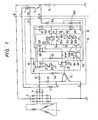
- reference numeral 1 represents an armature winding of a generator; 2 is a three-phase full-wave rectifier; and 3 is a field winding.
- Reference numeral 4 represents an auxiliary rectifier; 5 is a battery; 6 is a key switch; and 7 is a charge pilot lamp.
- Reference numeral 8 represents a voltage regulator consisting of a hybrid IC; 9 is a reference voltage generating circuit; 10 is a monolithic IC fitted onto the hybrid IC; 11 is a power transistor; 12 is a flywheel diode; 13 is an initial excitation resistor; 14 and 15 are resistors; and 16a and 16b are voltage division resistors.
- Reference numeral 17 represents a comparison circuit.
- the monolithic IC consists of a power source circuit composed of a zenor diode 20, transistors 21 , 22, a resistor 23 and transistors 24, 25, 26 .
- the reference voltage generating circuit 9 is constituted by thick film resistors 91 , 92, 93, 94, 95 and transistors 101 through 108 on the monolithic IC
- the voltage of the battery 5 is applied to an IG terminal, the zenor diode 20 is excited and a power source voltage V cc of the monolithic IC is generated.
- the transistors 21 and 22 function as diodes because their collectors and bases are short-circuited, respectively.
- the voltage of the battery 5 is applied to an S terminal, is divided by the voltage dividers 16a, 16b and is compared with a reference voltage V ref by the comparison circuit 17.
- the regulated voltage of the battery 5 is determined as expressed by equation (3) from the following equations (1) and (2):
- each transistor 101 - 103 Since the collector and base of each transistor 101 - 103 are short-circuited, the transistor functions as a diode . Its voltage value varies with temperature, and a voltage V 1 at the junction between resistors 91 and 92 also changes with the temperature . The voltage V 2 at the point between resistors 94 and 95 does not change unless V cc changes with temperature .
- the PN junction forward voltage of silicon diodes generally has a negative temperature gradient so that it is higher at a lower temperature. When the junction temperature of the transistors 101 - 103 is sufficiently low, the collector voltage of the transistor 101 does not exceed V 1 any longer, and substantially no current flows through the transistors 101 - 103. Therefore, the voltage V does not change at a temperature lower than a certain temperature, and shows low temperature saturation characteristics .
- V 3 can be expressed as follows:
- V ref is higher by V BE than V 3 , and can be expressed as follows:
- the transistor 106 operates so as to offset the voltage drop due to the transistor 104 or 105 .
- V ref Since the collector voltage of the transistor 101 drops at high temperature, V 1 also drops with an increasing temperature .
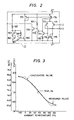
- V 2 is set to be lower than V at normal temperature, V ref does not become lower than V 2 even if V drops at high temperatures . Therefore, V ref exhibits characteristics that go into saturation at low and high temperature ranges, as represented by dashed lines in Fig. 3 .
- the equation (5) is established when the voltage drop of the transistor 106 is equal to that of the transistor 104 or 105 .
- the base-to- emitter voltage of transistors is generally expressed by the following equation:
- I 3 current flowing through transistor 108.
- the voltage drop of the transistor 106 is equal to that of the transistor 104 or 105, and the equation (5) can be established constantly.
- the current value of the transistor 25 is equal to that of the transistor 26, and the current value of the transistor 26 is equal to that of the transistor 107 due to the current mirror effect. Therefore, the current value of the transistor 107 is equal to that of the transistor 106 provided that a current flowing into the comparison circuit 17 is neglected.
- I 1 is equal to the value of the current flowing through the transistor 25 . Since V BE of the transistor 25 is equal to that of the transistor 108, the current flowing through the transistor 108 becomes twice that of the transistor 25 and the equation (8) can be satisfied if the emitter area of the transistor 108 is set to be twice from the equation (6) .
- the temperature characteristics obtained from the circuit of the present invention can be quantitatively analyzed as follows . First of all, the resistance values are determined as listed below .
- the saturation voltage V H at a low temperature is equal to the voltage obtained by dividing V cc by the resistors 91 and 92, and can be expressed as follows:
- V L at a high temperature is equal to V 2 , and can be expressed as follows:
- V ref is equal'to V and can be expressed as follows:
- V is given as follows:
- the change quantity of V 1 with respect to the temperature change can be obtained by calculating a partial differential from V with T using V BE as a function of T, and can be expressed as follows: aV BE /aT can be calculated as follows by making partial differential of the equation (6) by T:
- V ref and a practical regulated voltage have the proportional relationship as provided by the equation (3), and the result of calculation of the characteristics by providing a suitable circuit constants is indicated by dashed lines in Fig. 3.
- the circuit constants are as follows:
- the curve represented by solid line in Fig. 3 represents a measured values and its gradient is less linear in the vicinity of 0 0 C and 100°C than that of the calculated value .
- V BE exhibits non-saturation characteristics when switching between low, medium and high temperatures, but does not present any practical problem.
- the regulator of the aforementioned Japanese Patent Laid-Open No. 55-37843 cited as an example of the prior art technique exhibits similar characteristics because it uses the forward characteristics of a transistor for the limiter circuit.
- This embodiment can reduce the number of transistors, that constitute the reference voltage generation circuit having the temperature characteristics, 17 in the prior art, to only 8 in this device. Therefore, the chip area of the monolithic IC can be reduced and the cost of production can also be reduced .
- the number of terminals for connection with external resistors has been 4, this embodiment reduces that to 3 .
- the number of terminals corresponds to the number of bonding pads of the IC chip . Therefore, since the number of terminals is reduced, the number of bonding pads can be reduced so that the production steps can be simplified and the cost of production can be reduced. Since the maximum value circuit and the minimum value circuit are combined with each other, the function trimming of the thick film resistors can be made more easily .
- Fig. 4 shows another embodiment of the present invention.
- the portion of the reference voltage generating circuit 9 in Fig. 1 is improved and represented by an improved circuit 9a.
- reference numerals 91 a, 92a, 94a and 95a are also voltage division resistors, respectively.
- Reference numerals 93a and 96a represent resistors, and reference numerals 109, 110, 111 and 112 represent NPN transistors .
- the voltage V 4 ' at the junction of the transistors 104 and 105 can be expressed as follows:
- the voltage V ' at the junction of the transistors 109 and 110 can be expressed as follows because the lower voltage of the emitter voltages of the transistcrs 109 and 110 is transmitted:
- V ref is given as follows by reducing the forward voltage drop V BE of the transistor 11 2 from V 5 ' :
- V ref by the equation (20) exhibits the characteristics represented by solid line in Fig. 5, and is equivalent to the first embodiment of the present invention .
- the equation (20) can be established only when the current flowing through each of the transistors is equal, in the same way as in the first embodiment.
- the current flowing through each transistor is as follows:
- this embodiment can set V 1 ' and V 3 ' by adjusting the ratio of the voltage division resistors, and can set the temperature gradient independently of V 1 ' and V 3 ' by means of the resistors 93a and 96a.
- Fig. 6 is a circuit diagram of a charge system including a generator which is driven by an engine (not shown) .
- reference numeral 1 represents an armature winding of a generator
- 3 is a field winding which supplies a magnetic flux to the armature winding 1
- 2 is a three-phase full-wave rectifier for converting the a .c. output of the armature winding 1 to a d .c .
- 4 is an auxiliary rectifier 4
- 5 is a battery which is connected to and charged by the three-phase full-wave rectifier 2 and supplies a current to an external load (not shown).
- Reference numeral 6 represents a key switch, and 7 a charge pilot lamp .
- Reference numeral 8 represents a voltage regulator which is formed by a hybrid thick film integrated circuit and consists of a power transistor 209, a monolithic IC 210 for control, a flywheel diode 211 , resistors 212, 213 and voltage division registers 214a, 214b, 215a, 215b.
- the control monolithic IC 210 consists of a zener diode 301 , a constant voltage circuit formed by a diode 302, a comparator 303, voltage division resistors 304a, 304b, a resistor 305 for generating a constant current, NPN transistors 306, 307, 308, PNP transistors 309, 310 and diodes 311, 312, 313.
- the voltage at the voltage division point of the voltage division resistors 214a, 214b is higher than the voltage at the voltage division point of the voltage division resistors 304a, 304b, so that the output of the comparator 103 is at a low level, the power transistor 209 is cut off and the field current attenuate through the flywheel diode 211 .
- the output voltages of the generator and the battery 5 also decrease . These operations are repeated and the voltage of the battery 5 is controlled to a predetermined value.
- V BE is a base-emitter voltage of the transistor or a forward voltage drop of a diode .
- anode potential V 2 of the diode 113 can be expressed as follow s:
- the voltage at the S terminal is controlled to a predetermined value .
- this embodiment effects the detection of the auxiliary voltage for the voltage of the generator even if the voltage detection terminals come off, and the generator voltage is controlled to a predetermined value.
- the current flowing through the diode 311 or 312 must be equal to the current flowing through the diode 313 .
- the base-emitter voltage of a transistor can be expressed as follows:
- the diodes 311, 312 and 313. are obtained by short-circuiting the collector and base of the transistors.
- the transistor 306 causes a reference constant current, which is determined by the resistor 305, to flow from the constant voltage circuit, and this current will be called "I 1 " .
- I 1 a current equal to I 1 flows .
- This current drives the transistor 309, and the same current, that is, I 1 , flows also through the transistor 310 that is connected in the current mirror arrangement.
- the voltage of the battery 5 can be detected accurately irrespective of temperatures and the like . Therefore, the battery charging performance can be improved.
Landscapes
- Engineering & Computer Science (AREA)
- Power Engineering (AREA)
- Control Of Charge By Means Of Generators (AREA)
Applications Claiming Priority (4)
| Application Number | Priority Date | Filing Date | Title |
|---|---|---|---|
| JP16555/85 | 1985-02-01 | ||
| JP60016555A JPS61177128A (ja) | 1985-02-01 | 1985-02-01 | 発電機の電圧調整装置 |
| JP30411/85 | 1985-02-20 | ||
| JP3041185A JPS61191239A (ja) | 1985-02-20 | 1985-02-20 | 車両用交流発電機の電圧調整装置 |
Publications (2)
| Publication Number | Publication Date |
|---|---|
| EP0189885A2 true EP0189885A2 (de) | 1986-08-06 |
| EP0189885A3 EP0189885A3 (de) | 1988-04-20 |
Family
ID=26352919
Family Applications (1)
| Application Number | Title | Priority Date | Filing Date |
|---|---|---|---|
| EP86101058A Ceased EP0189885A3 (de) | 1985-02-01 | 1986-01-27 | Spannungsregler für einen in einem Auto eingesetzten Generator |
Country Status (3)
| Country | Link |
|---|---|
| US (1) | US4680530A (de) |
| EP (1) | EP0189885A3 (de) |
| CN (1) | CN1004956B (de) |
Cited By (11)
| Publication number | Priority date | Publication date | Assignee | Title |
|---|---|---|---|---|
| FR2624320A1 (fr) * | 1987-12-02 | 1989-06-09 | Equip Electr Moteur | Regulateur monolithique de tension de charge de batterie par un alternateur protege contre les tensions parasites |
| EP0330561A1 (de) * | 1988-02-23 | 1989-08-30 | Valeo Equipements Electriques Moteur | Mehrfunktionsregeleinrichtung mit Taktsynchronwechselstromerzeuger |
| FR2642580A1 (fr) * | 1989-01-11 | 1990-08-03 | Equip Electr Moteur | Regulateur plurifonction a cadencement synchrone de l'alternateur |
| EP0335085A3 (en) * | 1988-03-26 | 1990-11-22 | Nippondenso Co., Ltd. | Charging control unit and method for motor vehicle |
| WO1991000635A1 (en) * | 1989-06-30 | 1991-01-10 | Analog Devices, Inc. | Storage battery charging control apparatus with temperature-sensitive voltage monitoring apparatus |
| EP0350077A3 (de) * | 1988-07-07 | 1991-01-23 | Mitsubishi Denki Kabushiki Kaisha | Steuervorrichtung für einen Fahrzeugwechselstromgenerator |
| DE4035337A1 (de) * | 1990-11-07 | 1992-05-14 | Daimler Benz Ag | Verfahren zur verbesserung des ladezustandes von einer bordbatterieanordnung im kraftfahrzeug |
| EP0498727A1 (de) * | 1991-02-07 | 1992-08-12 | Valeo Equipements Electriques Moteur | Schaltung, die eine temperaturabhängige Referenzspannung produziert, vor allem zur Regulierung der Batterieladungsspannung von einem Wechselstromgenerator |
| EP0557739A1 (de) * | 1992-02-26 | 1993-09-01 | Motorola, Inc. | Thermisch abhängige, selbständernde Spannungsquelle |
| US5339018A (en) * | 1989-06-30 | 1994-08-16 | Analog Devices, Inc. | Integrated circuit monitor for storage battery voltage and temperature |
| WO1995020783A1 (de) * | 1994-01-27 | 1995-08-03 | Robert Bosch Gmbh | Integrierte schaltung |
Families Citing this family (11)
| Publication number | Priority date | Publication date | Assignee | Title |
|---|---|---|---|---|
| JP2751174B2 (ja) * | 1988-02-01 | 1998-05-18 | 株式会社デンソー | 車両の充電制御装置 |
| JP3209519B2 (ja) * | 1988-08-26 | 2001-09-17 | 富士通株式会社 | 電子回路 |
| US4990846A (en) * | 1990-03-26 | 1991-02-05 | Delco Electronics Corporation | Temperature compensated voltage reference circuit |
| US5079716A (en) * | 1990-05-01 | 1992-01-07 | Globe-Union, Inc. | Method and apparatus for estimating a battery temperature |
| US5298851A (en) * | 1992-05-12 | 1994-03-29 | Transpo Electronics, Inc. | Multiple application voltage regulator system and method |
| JP3213543B2 (ja) * | 1996-04-18 | 2001-10-02 | 株式会社ミツバ | 自動車用充電電圧制御回路 |
| DE69737379T2 (de) * | 1996-04-23 | 2007-10-31 | Denso Corp., Kariya | Spannungsregelungssystem für ein Fahrzeug mit Lichtmaschine |
| JP2000050696A (ja) * | 1998-08-03 | 2000-02-18 | Sawafuji Electric Co Ltd | 発動発電機用自動電圧調整装置 |
| DE102006026666A1 (de) * | 2006-06-08 | 2007-12-20 | Atmel Germany Gmbh | Schaltung zur Überwachung einer Batteriespannung |
| CN201032692Y (zh) * | 2007-03-16 | 2008-03-05 | 朋程科技股份有限公司 | 车用发电机的调节器 |
| JP2012209762A (ja) * | 2011-03-30 | 2012-10-25 | Hitachi Ltd | レベル生成回路 |
Family Cites Families (12)
| Publication number | Priority date | Publication date | Assignee | Title |
|---|---|---|---|---|
| US3469168A (en) * | 1967-09-19 | 1969-09-23 | Gen Motors Corp | Voltage protection circuit for transistor regulators |
| US3535616A (en) * | 1968-04-08 | 1970-10-20 | Motorola Inc | Temperature responsive automotive voltage regulator |
| DE1763349C3 (de) * | 1968-05-10 | 1978-10-12 | Robert Bosch Gmbh, 7000 Stuttgart | Spannungsregler |
| GB1298062A (en) * | 1968-11-11 | 1972-11-29 | Butec Ltd | Improvements in or relating to battery charging arrangements |
| US3736489A (en) * | 1971-05-21 | 1973-05-29 | Gen Electric | Temperature sensing system for rechargeable batteries |
| GB2000648B (en) * | 1977-07-02 | 1982-02-24 | Lucas Industries Ltd | Automatic battery charging system |
| AU520467B2 (en) * | 1977-07-02 | 1982-02-04 | Lucas Industries Limited | Temperature-compensated vehicle battery charging |
| DE3068863D1 (en) * | 1979-05-28 | 1984-09-13 | Nippon Denso Co | Generation control apparatus for vehicle generators |
| US4385270A (en) * | 1982-05-12 | 1983-05-24 | Motorola Inc. | Temperature limited voltage regulator circuit |
| US4459489A (en) * | 1982-09-30 | 1984-07-10 | General Motors Corporation | Generator load response control |
| JPS59148537A (ja) * | 1983-02-10 | 1984-08-25 | 株式会社日立製作所 | 充電発電機用電圧調整装置 |
| JPS60121932A (ja) * | 1983-12-05 | 1985-06-29 | 株式会社デンソー | 車両充電発電機用制御装置 |
-
1986
- 1986-01-27 EP EP86101058A patent/EP0189885A3/de not_active Ceased
- 1986-01-30 US US06/824,087 patent/US4680530A/en not_active Expired - Fee Related
- 1986-01-31 CN CN86100872.3A patent/CN1004956B/zh not_active Expired
Cited By (14)
| Publication number | Priority date | Publication date | Assignee | Title |
|---|---|---|---|---|
| FR2624320A1 (fr) * | 1987-12-02 | 1989-06-09 | Equip Electr Moteur | Regulateur monolithique de tension de charge de batterie par un alternateur protege contre les tensions parasites |
| EP0330561A1 (de) * | 1988-02-23 | 1989-08-30 | Valeo Equipements Electriques Moteur | Mehrfunktionsregeleinrichtung mit Taktsynchronwechselstromerzeuger |
| EP0335085A3 (en) * | 1988-03-26 | 1990-11-22 | Nippondenso Co., Ltd. | Charging control unit and method for motor vehicle |
| EP0350077A3 (de) * | 1988-07-07 | 1991-01-23 | Mitsubishi Denki Kabushiki Kaisha | Steuervorrichtung für einen Fahrzeugwechselstromgenerator |
| FR2642580A1 (fr) * | 1989-01-11 | 1990-08-03 | Equip Electr Moteur | Regulateur plurifonction a cadencement synchrone de l'alternateur |
| US5339018A (en) * | 1989-06-30 | 1994-08-16 | Analog Devices, Inc. | Integrated circuit monitor for storage battery voltage and temperature |
| WO1991000635A1 (en) * | 1989-06-30 | 1991-01-10 | Analog Devices, Inc. | Storage battery charging control apparatus with temperature-sensitive voltage monitoring apparatus |
| DE4035337A1 (de) * | 1990-11-07 | 1992-05-14 | Daimler Benz Ag | Verfahren zur verbesserung des ladezustandes von einer bordbatterieanordnung im kraftfahrzeug |
| US5278488A (en) * | 1990-11-07 | 1994-01-11 | Mercedes-Benz Ag | Process for improving the charge state of a battery arrangement in a motor vehicle |
| FR2672705A1 (fr) * | 1991-02-07 | 1992-08-14 | Valeo Equip Electr Moteur | Circuit generateur d'une tension de reference variable en fonction de la temperature, notamment pour regulateur de la tension de charge d'une batterie par un alternateur. |
| US5309083A (en) * | 1991-02-07 | 1994-05-03 | Valeo Equipements Electriques Moteur | Circuit for generating a reference voltage that varies as a function of temperature, in particular for regulating the voltage at which a battery is charged by an alternator |
| EP0498727A1 (de) * | 1991-02-07 | 1992-08-12 | Valeo Equipements Electriques Moteur | Schaltung, die eine temperaturabhängige Referenzspannung produziert, vor allem zur Regulierung der Batterieladungsspannung von einem Wechselstromgenerator |
| EP0557739A1 (de) * | 1992-02-26 | 1993-09-01 | Motorola, Inc. | Thermisch abhängige, selbständernde Spannungsquelle |
| WO1995020783A1 (de) * | 1994-01-27 | 1995-08-03 | Robert Bosch Gmbh | Integrierte schaltung |
Also Published As
| Publication number | Publication date |
|---|---|
| US4680530A (en) | 1987-07-14 |
| CN1004956B (zh) | 1989-08-02 |
| CN86100872A (zh) | 1986-07-30 |
| EP0189885A3 (de) | 1988-04-20 |
Similar Documents
| Publication | Publication Date | Title |
|---|---|---|
| US4680530A (en) | Voltage regulator for generator used in automobile | |
| US4563631A (en) | Voltage regulator for charging generator | |
| US4788486A (en) | Vehicular power supply system having a plurality of power supply voltages | |
| US4791349A (en) | Electric power system | |
| GB1567420A (en) | Closed loop system equipped with a device for producing a reference signal in accordance with the output signal of a gas sensor for internal combustion engine | |
| JPS6350942B2 (de) | ||
| US5266882A (en) | Control device for an alternating current generator of a vehicle | |
| US4398140A (en) | Control apparatus for charging generator | |
| US4409539A (en) | Self-excitation for an alternator of the low-carbon steel rotor type | |
| US4594631A (en) | Temperature protective circuit for a charging generator | |
| GB2144887A (en) | Voltage regulators | |
| US4945299A (en) | Control apparatus for an a.c. generator for automobile | |
| US4435676A (en) | Regulator for controlling output from generator having ambient temperature override | |
| US4295087A (en) | Charge indicator circuit for a battery charging system | |
| JPS58108930A (ja) | 固定周波電圧調整器 | |
| US4694239A (en) | Electronic voltage regulating device with compensation for thermal dissipation, particularly for alternators | |
| US5241261A (en) | Thermally dependent self-modifying voltage source | |
| JPH08294239A (ja) | 電圧調整回路 | |
| JPH0668709B2 (ja) | 電圧安定化装置 | |
| US3544881A (en) | Transistor voltage and current regulating system for an alternating current generator | |
| JPS5816019B2 (ja) | デンアツチヨウセイソウチ | |
| US3521148A (en) | Semiconductor voltage regulator for a generator with main and bucking field windings | |
| US4695786A (en) | Voltage regulator for an alternator having an auxiliary stage for starting the alternator at a low rotational speed | |
| US4395673A (en) | Controlled rectifier motor vehicle battery charger | |
| JPS5915231Y2 (ja) | 充電発電機制御装置 |
Legal Events
| Date | Code | Title | Description |
|---|---|---|---|
| PUAI | Public reference made under article 153(3) epc to a published international application that has entered the european phase |
Free format text: ORIGINAL CODE: 0009012 |
|
| AK | Designated contracting states |
Kind code of ref document: A2 Designated state(s): CH DE FR GB IT LI NL SE |
|
| PUAL | Search report despatched |
Free format text: ORIGINAL CODE: 0009013 |
|
| AK | Designated contracting states |
Kind code of ref document: A3 Designated state(s): CH DE FR GB IT LI NL SE |
|
| 17P | Request for examination filed |
Effective date: 19880421 |
|
| 17Q | First examination report despatched |
Effective date: 19901025 |
|
| STAA | Information on the status of an ep patent application or granted ep patent |
Free format text: STATUS: THE APPLICATION HAS BEEN REFUSED |
|
| 18R | Application refused |
Effective date: 19910602 |
|
| RIN1 | Information on inventor provided before grant (corrected) |
Inventor name: MASHINO, KEIICHI |