EP0189915A2 - Stuhl mit neigungsverstellbarer Rückenlehne - Google Patents
Stuhl mit neigungsverstellbarer Rückenlehne Download PDFInfo
- Publication number
- EP0189915A2 EP0189915A2 EP86101167A EP86101167A EP0189915A2 EP 0189915 A2 EP0189915 A2 EP 0189915A2 EP 86101167 A EP86101167 A EP 86101167A EP 86101167 A EP86101167 A EP 86101167A EP 0189915 A2 EP0189915 A2 EP 0189915A2
- Authority
- EP
- European Patent Office
- Prior art keywords
- frame
- supporting frames
- side sections
- section
- sections
- Prior art date
- Legal status (The legal status is an assumption and is not a legal conclusion. Google has not performed a legal analysis and makes no representation as to the accuracy of the status listed.)
- Granted
Links
Images



Classifications
-
- A—HUMAN NECESSITIES
- A47—FURNITURE; DOMESTIC ARTICLES OR APPLIANCES; COFFEE MILLS; SPICE MILLS; SUCTION CLEANERS IN GENERAL
- A47C—CHAIRS; SOFAS; BEDS
- A47C1/00—Chairs adapted for special purposes
- A47C1/02—Reclining or easy chairs
- A47C1/031—Reclining or easy chairs having coupled concurrently adjustable supporting parts
- A47C1/032—Reclining or easy chairs having coupled concurrently adjustable supporting parts the parts being movably-coupled seat and back-rest
- A47C1/03294—Reclining or easy chairs having coupled concurrently adjustable supporting parts the parts being movably-coupled seat and back-rest slidingly movable in the base frame, e.g. by rollers
-
- A—HUMAN NECESSITIES
- A47—FURNITURE; DOMESTIC ARTICLES OR APPLIANCES; COFFEE MILLS; SPICE MILLS; SUCTION CLEANERS IN GENERAL
- A47C—CHAIRS; SOFAS; BEDS
- A47C1/00—Chairs adapted for special purposes
- A47C1/02—Reclining or easy chairs
- A47C1/031—Reclining or easy chairs having coupled concurrently adjustable supporting parts
- A47C1/032—Reclining or easy chairs having coupled concurrently adjustable supporting parts the parts being movably-coupled seat and back-rest
- A47C1/03205—Reclining or easy chairs having coupled concurrently adjustable supporting parts the parts being movably-coupled seat and back-rest having adjustable and lockable inclination
- A47C1/0325—Reclining or easy chairs having coupled concurrently adjustable supporting parts the parts being movably-coupled seat and back-rest having adjustable and lockable inclination by means of clamps or friction locking members
Definitions
- the present invention relates in general to chairs, and more particularly to reclining chairs of a type wherein a seat cushion portion and a seatback portion are pivotally connected to achieve simultaneous pivotal movements thereof.
- a reclining chair which comprises a pair of supporing frames which are spaced from each other, cross members each extending between the supporting frames to assure tight assembly of the same, a first generally U-shaped frame including a base section and two side sections, the first frame being movably disposed in the supporting frames with the base section directed in one direction and the side sections directed in the opposite direction, a second generally U-shaped frame including a base section and two side sections, the second frame being pivotally connected at the side sections thereof to the supporting frames with the base section thereof downwardly projected into the space between the supporting frames, pivot means for providing a pivot connection between the leading end of each side section of the first frame and the donwward projected portion of the second frame, a position adjuster mounted to each of the supporting frames to permit, under inoperative condition, axial movement of each side section of the first frame relative to the supporting frames and to secure, under operative condition, each side section of the first frame to the supporting frames, a first sheet spreaded between the respective base sections of the first and second
- forward and rearward are to be understood as referring to “in the direction of the front of the chair” and “in the direction of the rear of the chair”, and the terms “right” and “left” to be taken as “right” and “left” with respect to a person sitting on the chair.
- a first embodiment of the present invention which is a single chair generally designated by numeral 10.
- the chair 10 compreses two identical pipe frames or supporting frames 12 and 14 which are spaced parallelly from each other, each having a generally
- each cross pipe 16 or 18 and each frame 12 or 14 is made by a conventional bolt-and-nut connection.
- a seat cushion portion 20 and a seatback portion 22 are pivotally supported by the combined supporting frames 12 and 14 in the following manner.
- the description of the seatback portion 22 will be commenced prior to that of the seat cushion portion 20.
- the seatback portion 22 comprises a generally U-shaped pipe frame or seatback frame 24 which thus includes a base section 24A and two side sections 24B and 24C.
- the side sections 24B and 24C of the pipe frame 24 are bent backward at their generally middle portions.
- the side sections 24B and 24C of the pipe frame 24 are received between the upper sections 12D and 14D, and pivotally connected at their bent portions to the rear portions of the upper sections 12D and 14D of the supporting frames 12 and 14.
- externally threaded pivot bolts 26 and 28 are used, each passing through the side section 24B (or 24C) of the seatback frame 24 and the upper section 12D (or 14D) of the supporting frame 12 (or 14).
- each bolt 26 (or 28) is held in place by a corresponding nut secured thereto. It is thus to be noted that the U-shaped seatback frame 24 is swingable forward and rearward about the pivoted portions relative to the combined supporting frames 12 and 14.
- stopper pins 30 (only one is shown in Fig. 1) are fixed to the side sections 24B and 24C of the frame 24 just below the pivot bolts 26 and 28, which are brought into contact with the corresponding upper sections 12D and 14D upon swing of the seatback frame 24.
- a rectangular sheet 32 constructed of for example "canvas" is spreaded between the side sections 24B and 24C of the seatback frame 24 with its lateral sides sewed to the side sections 24B and 24C. As shown, the pivoted portions of the side sections 24B and 24C of the seatback frame 24 are exposed, that is, not covered by the sheet 32 in order to assure the pivotal movement of the seatback portion 22 relative to the supporting frames 12 and 14.
- the seat cushion portion 20 comprises a generally U-shaped pipe frame or seat cushion frame 34 which thus includes a base section 34A and two side sections 34B and 34C. As is seen from the drawings, the side sections 34B and 34C are bent upwardly at their middle portions for the purpose which will be described hereinafter. The leading or free ends of the side sections 34B and 34C are pivotally connected to the lower portions of the side sections 24B and 24C of the seatback frame 24 through respective pivot pins 33. A sheet 35 is spreaded between the base section 34A of the seat cushion frame 34 and the base section 24A of the seat back . frame 24. The front portions of the side sections 34B and 34C of the seat cushion frame 34 are supported by the supporting frames 12 and 14 in the following manner.
- a pair of position adjusters 36 and 38 are employed, each being arranged between the front portion of the side section 34B (or 34C) of the seat cushion frame 34 and the front section 12B (or 14B) of the supporting frame 12 (or 14). Since these two position adjusters 36 and 38 have substantially the same constructions, only one of them (that is the adjuster 36) will be described in the next for simplification of the description.
- the adjuster 36 comprises a generally U-shaped resilient bracket 40 and a pair of grippers 42 and 44 which are received in the bracket 40.
- the grippers 42 and 44 are respectively formed with semicircular recesses 42A and 44A at their inboard sides, so that upon mounting, the tubular side section 34B of the seat cushion frame 34 is axially slidably received in the recesses 42A and 44A.
- Designated by numeral 46 is a semicylindrical protecting plate which is interposed between the outboard gripper 44 and the side section 34B of the seat cushion frame 34 and secured to the side section 34B through bolts 48 (see Fig.
- the U-shaped bracket 40 and the paired grippers 42 and 44 are formed with aligned bores 40A, 42B and 44B through which a tubular portion 50A of a supporter 50 passes.
- the tubular portion 50A is shorter than the axial length of the aligned bores 40A, 42B and 44B.
- the supporter 50 is securely connected through a reinforcing plate 52 to the front section 12B of the supporting frame 12. In the illustrated embodiment, the supporter 50 is welded to the reinforcing plate 52 at its circular base portion 50B. With this, it will be appreciated that the unit including the bracket 40 and the paired grippers 42 and 44 is pivotal about the tubular portion 50A of the supporter 50.
- the inside surface of the tubular portion 50A of the supporter 50 is threaded.
- An externally threaded bolt portion 54A of a handling knob 54 is received in and engaged with the internal thread of the tubular portion 50A of the supporter 50.
- the U-shaped bracket 40 is resiliently deformed causing the grippers 42 and 44 to tightly catch the side section 34B of the seat cushion frame 34.
- tight connection between the side section 34B of the frame 34 and the front section 12B of the supporting frame 12A is achieved.
- the other position adjuster 38 functions to achieve tight connection between the side section 34C of the cushion frame 34 and the front section 14B of the supporting frame 14.
- the handling knobs 54 of the position adjusters 36 and 38 are loosed, and the seatback portion 22 is manually swung forward or reaward to a desired position. With this movement of the seatback portion 22, the seat cushion portion 20 is swung about the position adjusters 36 and 38 permitting sliding of the side sections 34B and 34C of the seat cushion frame 34 in the adjusters 36 and 38. Then, the knobs 54 are fastened to tightly hold the newly set posture of the chair 10.
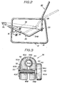
- the posture change of the chair 10 can be effected with a person sitting on the seat cushion portion 20 because of the pivotal movement of the adjusters 36 and 38 under unfastened condition of the handling knobs 54. That is, as is seen from Fig. 2, when a person sitting on the seat cushion portion 20 which assume the position illustrated by a phantom line inclines his or her upper half forward, the seat cushion portion 20 is swung down to the position illustrated by a solid line due to the resultant force M 1 applied to the seat cushion frame 34 in the direction parallel to the axis of each side section 34B or 34C of the frame 34. While, when the person sitting on the seat cushion portion 20 inclines his or her upper half rearward, the seat cushion portion 20 is swung up to the position illustrated by the phantom line against the resultant force M 1 applied to the seat cushion portion 20.
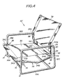
- FIG. 4 there is shown a second embodiment of the present invention.
- the chair 10' of the second embodiment comprises substantially the same parts as those of the afore-mentioned first embodiment except the pivoting means for pivotally connecting the seat cushion frame 34 to the seatback frame 24. That is, in the second embodiment, two brackets 56 (only one is shown in Fig. 4) are employed as elements of the pivoting means. As is best shown in Figs. 6 and 7, each bracket 56 comprises a base section 56A secured to one side section 24B (or 24C) of the seatback frame 24, and an arm section 56B raised from the base section 56A. The leading or free end of the side section 34B (or 34C) of the seat cushion frame 34 is pivotally connected to the arm section 56B through a pivot pin 58. As is seen from Fig. 7, the pivot pin 58 is arranged to be coaxial with the base section 24A of the seatback frame 24.
- the length between the base section 34A of the seat cushion frame 34 and the base section 24A of the seatback frame 24 is kept constant regardless of postures which the chair 10" assume. This induces constant tightening of the sheet 35 of the seat cushion portion thereby improving the external appearance of the chair 10'.
- the advantages of the first embodiment are also achieved in the second embodiment.
- a twin chair 10" of a third embodiment of the present invention is shown. As will become apparent as the description proceeds, the twin chair 10" is constructed to combine two similar chairs.
- the twin chair 10" of the third embodiment comprises two, namely, right and left chairs 10"A and 10"B each being a slight modification of the chair 10' of the second embodiment.
- each chair 10"A or 10"B which differ from those of the second embodiment, will be described in the following.
- each of the chairs 10"A and 10"B has only one position adjuster 36 or 38 which is arranged at the outboard side of the associated chair 10"A or 10"B in such a manner as has been described hereinafore.
- Each chair has at its inboard side a pivotal supporter 36' or 38' the cross section of which is shown in Fig. 11.
- the pivotal supporter 36' (or 38') comprises substantially the same parts as those of the position adjuster 36 except the handling knob 54. That is, as a substitute for the handling knob, the suppoer 36' uses a headed bolt 54A'. In practical use, the headed bolt 54A' is screwed to a position to permit not only sliding movement of the side section 34C relative to the pivotal supporter 36' but also pivotal movement of the supporter 36' relative to the front section 12B of the supporting frame 12.
- each of the connectors 60, 62 and 64 comprises a plastic hollow strut 66 which has semi-cylindrical recessed ends respectively mated with the inboard supporting frames 12 and 14.
- a headed internally threaded tubular shaft 68 is inserted through a hole of the pipe frame 14 into the plastic hollow strut 66.
- An externally threaded bolt 70 is inserted through the pipe frame ' 12 and engaged with the tubular shaft 68 in the strut 70. It is thus to be appreciated that a tight connection between the two frames 12 and 14 is achieved when the bolt 70 is tightly fastened.
Landscapes
- Health & Medical Sciences (AREA)
- Dentistry (AREA)
- General Health & Medical Sciences (AREA)
- Chairs For Special Purposes, Such As Reclining Chairs (AREA)
Applications Claiming Priority (6)
| Application Number | Priority Date | Filing Date | Title |
|---|---|---|---|
| JP1143785U JPH0330045Y2 (de) | 1985-01-30 | 1985-01-30 | |
| JP11437/85U | 1985-01-30 | ||
| JP26970/85U | 1985-02-26 | ||
| JP2697085U JPH0330047Y2 (de) | 1985-02-26 | 1985-02-26 | |
| JP26971/85U | 1985-02-26 | ||
| JP2697185U JPH0330048Y2 (de) | 1985-02-26 | 1985-02-26 |
Publications (3)
| Publication Number | Publication Date |
|---|---|
| EP0189915A2 true EP0189915A2 (de) | 1986-08-06 |
| EP0189915A3 EP0189915A3 (en) | 1987-04-29 |
| EP0189915B1 EP0189915B1 (de) | 1989-11-29 |
Family
ID=27279419
Family Applications (1)
| Application Number | Title | Priority Date | Filing Date |
|---|---|---|---|
| EP86101167A Expired EP0189915B1 (de) | 1985-01-30 | 1986-01-29 | Stuhl mit neigungsverstellbarer Rückenlehne |
Country Status (3)
| Country | Link |
|---|---|
| US (1) | US4660884A (de) |
| EP (1) | EP0189915B1 (de) |
| DE (1) | DE3667134D1 (de) |
Cited By (3)
| Publication number | Priority date | Publication date | Assignee | Title |
|---|---|---|---|---|
| FR2651657A1 (fr) * | 1989-09-08 | 1991-03-15 | Palanque Albert | Siege du type dont la partie d'assise presente deux plans d'appui, le premier est horizontal, le second est en plan incline en contre-pente vers la base du dossier. |
| US5967609A (en) * | 1996-11-18 | 1999-10-19 | Hwe, Inc. | Reclining chair with guide rail system |
| CN108451209A (zh) * | 2018-03-01 | 2018-08-28 | 望江县喜来美家具有限公司 | 一种拼接式仿藤椅 |
Families Citing this family (17)
| Publication number | Priority date | Publication date | Assignee | Title |
|---|---|---|---|---|
| NO168985C (no) * | 1987-10-19 | 1992-04-29 | Ekornes Fabrikker As J E | Anordning ved stol. |
| FI81952C (sv) * | 1988-09-09 | 1991-01-10 | Mekrapid | Låsmekanism för fällbar sittmöbel |
| US5209549A (en) * | 1991-05-28 | 1993-05-11 | Chang I Shan | Adjustable rotation chair |
| US6050642A (en) * | 1996-05-13 | 2000-04-18 | Erb; Scott C. | Multi-direction reclining and stretching chair |
| GB2326586A (en) * | 1997-06-25 | 1998-12-30 | Wallis Office Furniture Limite | Reclining chair |
| US6224159B1 (en) * | 1999-05-12 | 2001-05-01 | Charles Owen Perry | Flexible chair which can be disassembled to a flat configuration |
| DE10148645A1 (de) * | 2001-10-02 | 2003-04-10 | Dauphin Friedrich W Gmbh | Rückenlehne für einen Stuhl |
| US7165811B2 (en) * | 2002-09-12 | 2007-01-23 | Steelcase Development Corporation | Control mechanism for seating unit |
| US6715831B1 (en) * | 2003-05-16 | 2004-04-06 | Taiwan Shin Yeh Enterprise Co., Ltd. | Swing having seat units with tiltable backrests |
| US20050194823A1 (en) * | 2004-01-29 | 2005-09-08 | Perry Marco C. | Flexible chair with post base |
| US7131154B2 (en) * | 2005-02-24 | 2006-11-07 | Wood Lark Circle, Inc. | Mobile transport device |
| US7775590B2 (en) * | 2008-03-04 | 2010-08-17 | Ziming Shen | Knockdown chair having reinforced side supports |
| US7735925B2 (en) * | 2008-11-13 | 2010-06-15 | Zhongshan Kemi Commodity Co., Ltd. | Positioning device for chair |
| US7735924B2 (en) * | 2008-11-13 | 2010-06-15 | Chang-Chen Lin | Positioning device for chair |
| WO2011124027A1 (zh) * | 2010-04-07 | 2011-10-13 | Lin Jingheng | 具有自由滑滚联动机构的座椅家具 |
| US9717340B2 (en) | 2010-09-13 | 2017-08-01 | Tropitone Furniture Co., Inc. | Adjustable seating and furniture |
| US8534758B2 (en) | 2010-09-13 | 2013-09-17 | Tropitone Furniture Co., Inc. | Reclinable seating apparatus and method |
Family Cites Families (10)
| Publication number | Priority date | Publication date | Assignee | Title |
|---|---|---|---|---|
| US488095A (en) * | 1892-12-13 | Knockdown folding chair | ||
| US2512353A (en) * | 1946-04-16 | 1950-06-20 | Newburgh Metal Mfg Corp | Reclining chair |
| US2654417A (en) * | 1950-03-01 | 1953-10-06 | Newburgh Metal Mfg Corp | Foldable reclining chair |
| DE854249C (de) * | 1950-11-09 | 1952-11-04 | Bremshey & Co | Sitzmoebel, insbesondere fuer Fahrzeuge |
| US2812801A (en) * | 1955-11-15 | 1957-11-12 | Universal Converting Corp | Collapsible chair |
| US3248150A (en) * | 1965-02-10 | 1966-04-26 | Lilienfeld Beatrice | Chair construction |
| US3934932A (en) * | 1971-10-28 | 1976-01-27 | J.E. Ekornes Fabrikker A/S | Adjustable chair |
| BE799878A (fr) * | 1973-01-24 | 1973-09-17 | Lusch Ferdinand | Chaise longue reglable |
| JPS522656A (en) * | 1975-06-24 | 1977-01-10 | Nhk Spring Co Ltd | Chair |
| CH613127A5 (de) * | 1976-10-05 | 1979-09-14 | Ciba Geigy Ag |
-
1986
- 1986-01-28 US US06/823,455 patent/US4660884A/en not_active Expired - Fee Related
- 1986-01-29 EP EP86101167A patent/EP0189915B1/de not_active Expired
- 1986-01-29 DE DE8686101167T patent/DE3667134D1/de not_active Expired - Lifetime
Cited By (4)
| Publication number | Priority date | Publication date | Assignee | Title |
|---|---|---|---|---|
| FR2651657A1 (fr) * | 1989-09-08 | 1991-03-15 | Palanque Albert | Siege du type dont la partie d'assise presente deux plans d'appui, le premier est horizontal, le second est en plan incline en contre-pente vers la base du dossier. |
| US5967609A (en) * | 1996-11-18 | 1999-10-19 | Hwe, Inc. | Reclining chair with guide rail system |
| US6012774A (en) * | 1996-11-18 | 2000-01-11 | Hwe, Inc. | Reclining chair with guide rail system |
| CN108451209A (zh) * | 2018-03-01 | 2018-08-28 | 望江县喜来美家具有限公司 | 一种拼接式仿藤椅 |
Also Published As
| Publication number | Publication date |
|---|---|
| DE3667134D1 (de) | 1990-01-04 |
| EP0189915A3 (en) | 1987-04-29 |
| EP0189915B1 (de) | 1989-11-29 |
| US4660884A (en) | 1987-04-28 |
Similar Documents
| Publication | Publication Date | Title |
|---|---|---|
| US4660884A (en) | Reclining chair | |
| JPH054429Y2 (de) | ||
| CA1195227A (en) | Chair | |
| US7303234B2 (en) | Vehicle seating with arcuate motion support | |
| US6517156B1 (en) | Backrest structure for a leisure chair | |
| JPS60242808A (ja) | 椅子 | |
| US6296309B1 (en) | Chair construction | |
| CA1293683C (en) | Seat furniture | |
| GB2216788A (en) | Automotive seat with side-supports | |
| US4046422A (en) | Chair | |
| US6161897A (en) | Chair construction | |
| JP2000093250A (ja) | 椅子等の身体支持装置 | |
| EP1258216A3 (de) | Verstellvorrichtung für Betten und andere Liege- oder Sitzmöbel | |
| JPH0411870Y2 (de) | ||
| KR910004304Y1 (ko) | 의자 등받이 굴신장치 | |
| JPS6337882Y2 (de) | ||
| JP3622069B2 (ja) | 車椅子のフレーム | |
| JPH0451254U (de) | ||
| JPH077342U (ja) | 収穫機の操縦部構造 | |
| JPH0120233Y2 (de) | ||
| JPH0236535Y2 (de) | ||
| JP3654581B2 (ja) | ロッキング椅子 | |
| JPH0527879Y2 (de) | ||
| JPS6144670Y2 (de) | ||
| JP2984609B2 (ja) | 椅 子 |
Legal Events
| Date | Code | Title | Description |
|---|---|---|---|
| PUAI | Public reference made under article 153(3) epc to a published international application that has entered the european phase |
Free format text: ORIGINAL CODE: 0009012 |
|
| 17P | Request for examination filed |
Effective date: 19860129 |
|
| AK | Designated contracting states |
Kind code of ref document: A2 Designated state(s): DE FR GB |
|
| PUAL | Search report despatched |
Free format text: ORIGINAL CODE: 0009013 |
|
| AK | Designated contracting states |
Kind code of ref document: A3 Designated state(s): DE FR GB |
|
| 17Q | First examination report despatched |
Effective date: 19880504 |
|
| GRAA | (expected) grant |
Free format text: ORIGINAL CODE: 0009210 |
|
| AK | Designated contracting states |
Kind code of ref document: B1 Designated state(s): DE FR GB |
|
| REF | Corresponds to: |
Ref document number: 3667134 Country of ref document: DE Date of ref document: 19900104 |
|
| ET | Fr: translation filed | ||
| PLBE | No opposition filed within time limit |
Free format text: ORIGINAL CODE: 0009261 |
|
| PLBE | No opposition filed within time limit |
Free format text: ORIGINAL CODE: 0009261 |
|
| STAA | Information on the status of an ep patent application or granted ep patent |
Free format text: STATUS: NO OPPOSITION FILED WITHIN TIME LIMIT |
|
| 26N | No opposition filed | ||
| 26N | No opposition filed | ||
| PGFP | Annual fee paid to national office [announced via postgrant information from national office to epo] |
Ref country code: GB Payment date: 19911224 Year of fee payment: 7 |
|
| PGFP | Annual fee paid to national office [announced via postgrant information from national office to epo] |
Ref country code: FR Payment date: 19920110 Year of fee payment: 7 |
|
| PGFP | Annual fee paid to national office [announced via postgrant information from national office to epo] |
Ref country code: DE Payment date: 19920228 Year of fee payment: 7 |
|
| PG25 | Lapsed in a contracting state [announced via postgrant information from national office to epo] |
Ref country code: GB Effective date: 19930129 |
|
| GBPC | Gb: european patent ceased through non-payment of renewal fee |
Effective date: 19930129 |
|
| PG25 | Lapsed in a contracting state [announced via postgrant information from national office to epo] |
Ref country code: FR Effective date: 19930930 |
|
| PG25 | Lapsed in a contracting state [announced via postgrant information from national office to epo] |
Ref country code: DE Effective date: 19931001 |
|
| REG | Reference to a national code |
Ref country code: FR Ref legal event code: ST |