EP0190377A1 - Plaque de support pour carreaux - Google Patents
Plaque de support pour carreaux Download PDFInfo
- Publication number
- EP0190377A1 EP0190377A1 EP85101175A EP85101175A EP0190377A1 EP 0190377 A1 EP0190377 A1 EP 0190377A1 EP 85101175 A EP85101175 A EP 85101175A EP 85101175 A EP85101175 A EP 85101175A EP 0190377 A1 EP0190377 A1 EP 0190377A1
- Authority
- EP
- European Patent Office
- Prior art keywords
- tiles
- tile
- metal plate
- support plate
- flange portions
- Prior art date
- Legal status (The legal status is an assumption and is not a legal conclusion. Google has not performed a legal analysis and makes no representation as to the accuracy of the status listed.)
- Ceased
Links
- 239000002184 metal Substances 0.000 claims abstract description 31
- 239000004570 mortar (masonry) Substances 0.000 description 7
- 239000004568 cement Substances 0.000 description 2
- 238000000034 method Methods 0.000 description 2
- 210000002105 tongue Anatomy 0.000 description 2
- 230000001133 acceleration Effects 0.000 description 1
- 238000005336 cracking Methods 0.000 description 1
- 239000007788 liquid Substances 0.000 description 1
- 229920003023 plastic Polymers 0.000 description 1
- 239000004033 plastic Substances 0.000 description 1
- 238000003825 pressing Methods 0.000 description 1
- 238000003466 welding Methods 0.000 description 1
Images


Classifications
-
- E—FIXED CONSTRUCTIONS
- E04—BUILDING
- E04F—FINISHING WORK ON BUILDINGS, e.g. STAIRS, FLOORS
- E04F13/00—Coverings or linings, e.g. for walls or ceilings
- E04F13/07—Coverings or linings, e.g. for walls or ceilings composed of covering or lining elements; Sub-structures therefor; Fastening means therefor
- E04F13/08—Coverings or linings, e.g. for walls or ceilings composed of covering or lining elements; Sub-structures therefor; Fastening means therefor composed of a plurality of similar covering or lining elements
- E04F13/0801—Separate fastening elements
- E04F13/0832—Separate fastening elements without load-supporting elongated furring elements between wall and covering elements
- E04F13/0833—Separate fastening elements without load-supporting elongated furring elements between wall and covering elements not adjustable
- E04F13/0846—Separate fastening elements without load-supporting elongated furring elements between wall and covering elements not adjustable the fastening elements engaging holes or grooves in the side faces of the covering elements
-
- E—FIXED CONSTRUCTIONS
- E04—BUILDING
- E04F—FINISHING WORK ON BUILDINGS, e.g. STAIRS, FLOORS
- E04F13/00—Coverings or linings, e.g. for walls or ceilings
- E04F13/07—Coverings or linings, e.g. for walls or ceilings composed of covering or lining elements; Sub-structures therefor; Fastening means therefor
- E04F13/08—Coverings or linings, e.g. for walls or ceilings composed of covering or lining elements; Sub-structures therefor; Fastening means therefor composed of a plurality of similar covering or lining elements
- E04F13/0801—Separate fastening elements
- E04F13/0803—Separate fastening elements with load-supporting elongated furring elements between wall and covering elements
Definitions
- the present invention relates to a support plate for tiles to be set on the surface of a building.
- the conventional tiling method has another disadvantage that the lower rows of tiles will come off if the load of the tiles laid thereupon exceeds the limit which can be withstood by them. Because of this possibility, the number of rows of tiles which can be set in one day was restricted.
- the conventional tiling method has still another disadvantage that it requires a large quantity of mortar and that liquid cement has to be sprayed upon the surface of mortar for the acceleration of the hardening of mortar with a concomitant result of soiling the tiles and the surroundings with the cement.
- a support plate for tiles comprising a rectangular metal plate having a plurality of tile support pieces, said support pieces each having a web portion perpendicular to said metal plate and a flange portion parallel with said metal plate.
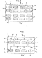
- a plurality of rectangular metal plates 1 are nailed or otherwise mounted on the surface of a building.
- L-shaped tile support pieces 5 are struck out of the surface of each metal plate 1 in such positions as to conform to the positions of tiles 2 to be arranged on the surface of the metal plate 1.
- the tile support pieces 5 are struck out of the surface of each metal plate 1 at intervals. Their end portions are bent in opposite directions, leaving webs 6 perpendicular to the metal plate 1. Flanges 7 are bent so as to run parallel with the metal plate 1.
- Each tile 2 designed for this embodiment is supported by two pairs of vertically spaced support pieces 5. (Fig. 2) In each pair of vertically spaced support pieces 5, the vertical length of the upper (i.e. downward) flange 7 is longer than that of the lower (i.e. upward) flange 7.
- the upper (downward) flanges 7 are fitted into a groove 3 provided in the upper edge of the tile 2. Then the lower (upward) flanges 7 are allowed to fit into a groove 4 provided in the lower edge of the tile 2.
- the groove 3 should be deeper than the groove 4.
- each tile 2 designed for this embodiment is provided with two grooves 8 running parallel with the metal plate. One of the grooves is provided in the back middle of the tile 2, while the other is provided in its lower edge. To mount the tile 2 on the metal plate 1 of this embodiment, the tile is lowered so that the upper edges of the flanges 7 will fit into the L-shaped grooves 8.
- each tile 2 designed for this embodiment is provided with a single L-shaped groove 8 in the back thereof to allow the flanges 7 to fit therein so that it can be mounted on the metal plate 1 of this embodiment in the same manner as in the second embodiment.
- tongues 11 formed by C-shaped cuts 10 in the metal plate 1 are pryed by means of a screwdriver or the like so as to bring the lower edges of the tongues 11 into contact with the upper edge of the tile 2 and thereby secure the tile in position.
- the tile support pieces 5 are substantially the same as those of the first embodiment except that the upper and lower flanges 7 are of the same length.
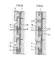
- Each tile 2 designed for this embodiment is provided with an L-shaped grooves 8 (Fig. 8) or a T-shaped groove 15 (Fig. 9) in the back thereof.
- the groove 8 or 15 is filled with mortar and then the tile 2 is pressed against the metal plate 1 and forced down so as to allow the upward flange 7 to fit into the vertical portion of the L- or T-shaped groove 8 or 15. Since the upper and lower flanges are of the same length, the support plates can be mounted upside down.
- the metal plate 1 may be of a larger size so as to be capable of bearing more than two rows of tiles 2.
- the metal plates 1 are secured to the surface of a building by means of nails 9 (Figs. 5, 6 and 7) driven through holes 12 (Figs. 2, 3 and 4).
- the metal plates 1 may be secured by spot welding.
- the space may be stuffed with mortar or foamed plastics poured through the openings 14 formed by striking the tile support pieces 5.
- the present invention obviates the necessity of stretching a string for aligning each row of tiles 2, and gives a good appearance to the tiled wall because of uniform space left between the tiles 2.
- the present invention has further advantages that it permits tile-setting without restrictions on the number of rows of tiles 2, that the metal plates 1 can be manufactured at low cost because the tile support pieces 5 can be formed simply by press work, and that the tiles 2 can be protected from cracking or peeling-off even if the tiled wall is jolted.
- the present invention has a still further advantage that since the metal plate 1 can be made in any curved form, the tiles can be easily set even on a curved wall surface.
Landscapes
- Engineering & Computer Science (AREA)
- Architecture (AREA)
- Civil Engineering (AREA)
- Structural Engineering (AREA)
- Finishing Walls (AREA)
Priority Applications (1)
| Application Number | Priority Date | Filing Date | Title |
|---|---|---|---|
| EP85101175A EP0190377A1 (fr) | 1985-02-05 | 1985-02-05 | Plaque de support pour carreaux |
Applications Claiming Priority (1)
| Application Number | Priority Date | Filing Date | Title |
|---|---|---|---|
| EP85101175A EP0190377A1 (fr) | 1985-02-05 | 1985-02-05 | Plaque de support pour carreaux |
Publications (1)
| Publication Number | Publication Date |
|---|---|
| EP0190377A1 true EP0190377A1 (fr) | 1986-08-13 |
Family
ID=8193278
Family Applications (1)
| Application Number | Title | Priority Date | Filing Date |
|---|---|---|---|
| EP85101175A Ceased EP0190377A1 (fr) | 1985-02-05 | 1985-02-05 | Plaque de support pour carreaux |
Country Status (1)
| Country | Link |
|---|---|
| EP (1) | EP0190377A1 (fr) |
Cited By (12)
| Publication number | Priority date | Publication date | Assignee | Title |
|---|---|---|---|---|
| US4803821A (en) * | 1987-03-05 | 1989-02-14 | Motokatsu Funaki | Tiled wall structure |
| WO1993023637A1 (fr) * | 1992-05-18 | 1993-11-25 | Whalley, Kevin | Systeme de montage permettant le revetement en pierre de constructions |
| EP0685614A1 (fr) * | 1994-06-01 | 1995-12-06 | Sarl Ft 3 R | Dispositif de fixation de plaques de revêtement |
| FR2722816A1 (fr) * | 1994-07-20 | 1996-01-26 | Lauragais Tuileries Briq | Systeme d'habillage d'une paroi verticale, compose de dalles de parement formant l'habillage de cette paroi, et de lisses de fixation desdites dalles de parement |
| EP0702119A2 (fr) * | 1994-09-15 | 1996-03-20 | William S. Shaw | Système de construction pour murs et toits |
| FR2746833A1 (fr) * | 1996-04-01 | 1997-10-03 | Lauragais Tuileries Briq | Element de bardage ainsi que son procede de mise en place |
| US5822937A (en) * | 1996-04-12 | 1998-10-20 | Boral Bricks (Nsw) Pty. Ltd. | Brick support |
| EP0936323A3 (fr) * | 1998-02-13 | 1999-10-20 | Balmet AG | Support pour éléments de revêtement de parois et revêtement de paroi ainsi obtenu |
| US6990778B2 (en) | 2002-09-18 | 2006-01-31 | Passeno James K | Brick veneer assembly |
| WO2007069027A3 (fr) * | 2005-12-13 | 2007-10-04 | Shouldice Designer Stone Ltd | Système de paroi en contreplaqué en pierres minces ou en briques minces et attaches correspondantes |
| WO2018224694A1 (fr) * | 2017-06-09 | 2018-12-13 | Masonry Support Systems Limited | Revêtement destiné à un élément de construction |
| EP3330449B1 (fr) | 2016-12-05 | 2025-07-23 | Masonry Support Systems Limited | Composant de construction |
Citations (4)
| Publication number | Priority date | Publication date | Assignee | Title |
|---|---|---|---|---|
| US2043706A (en) * | 1933-01-25 | 1936-06-09 | Kraftile Co | Tiling |
| US2832102A (en) * | 1957-01-22 | 1958-04-29 | Amoruso Joseph | Veneer wall construction |
| US3015193A (en) * | 1958-10-30 | 1962-01-02 | Amoruso Joseph | Shingled tile block veneer wall |
| GB2108173A (en) * | 1981-10-26 | 1983-05-11 | Gomei Kaisha Osawa Shoten | Apparatus for tile-setting |
-
1985
- 1985-02-05 EP EP85101175A patent/EP0190377A1/fr not_active Ceased
Patent Citations (4)
| Publication number | Priority date | Publication date | Assignee | Title |
|---|---|---|---|---|
| US2043706A (en) * | 1933-01-25 | 1936-06-09 | Kraftile Co | Tiling |
| US2832102A (en) * | 1957-01-22 | 1958-04-29 | Amoruso Joseph | Veneer wall construction |
| US3015193A (en) * | 1958-10-30 | 1962-01-02 | Amoruso Joseph | Shingled tile block veneer wall |
| GB2108173A (en) * | 1981-10-26 | 1983-05-11 | Gomei Kaisha Osawa Shoten | Apparatus for tile-setting |
Cited By (17)
| Publication number | Priority date | Publication date | Assignee | Title |
|---|---|---|---|---|
| US4803821A (en) * | 1987-03-05 | 1989-02-14 | Motokatsu Funaki | Tiled wall structure |
| US5634305A (en) * | 1992-05-18 | 1997-06-03 | Erlanger; Israel | System for stone cladding of buildings |
| WO1993023637A1 (fr) * | 1992-05-18 | 1993-11-25 | Whalley, Kevin | Systeme de montage permettant le revetement en pierre de constructions |
| EP0685614A1 (fr) * | 1994-06-01 | 1995-12-06 | Sarl Ft 3 R | Dispositif de fixation de plaques de revêtement |
| FR2720775A1 (fr) * | 1994-06-01 | 1995-12-08 | Ft 3 R | Dispositif de fixation de plaques de revêtement. |
| BE1009870A3 (fr) * | 1994-06-01 | 1997-10-07 | Ft 3 R Soc | Dispositif de fixation de plaques de revetement. |
| FR2722816A1 (fr) * | 1994-07-20 | 1996-01-26 | Lauragais Tuileries Briq | Systeme d'habillage d'une paroi verticale, compose de dalles de parement formant l'habillage de cette paroi, et de lisses de fixation desdites dalles de parement |
| EP0702119A2 (fr) * | 1994-09-15 | 1996-03-20 | William S. Shaw | Système de construction pour murs et toits |
| FR2746833A1 (fr) * | 1996-04-01 | 1997-10-03 | Lauragais Tuileries Briq | Element de bardage ainsi que son procede de mise en place |
| EP0799948A1 (fr) * | 1996-04-01 | 1997-10-08 | TUILERIES BRIQUETERIES DU LAURAGAIS GUIRAUD FRERES Société Anonyme | Elément de bardage ainsi que son procédé de mise en place |
| US5822937A (en) * | 1996-04-12 | 1998-10-20 | Boral Bricks (Nsw) Pty. Ltd. | Brick support |
| EP0936323A3 (fr) * | 1998-02-13 | 1999-10-20 | Balmet AG | Support pour éléments de revêtement de parois et revêtement de paroi ainsi obtenu |
| US6990778B2 (en) | 2002-09-18 | 2006-01-31 | Passeno James K | Brick veneer assembly |
| WO2007069027A3 (fr) * | 2005-12-13 | 2007-10-04 | Shouldice Designer Stone Ltd | Système de paroi en contreplaqué en pierres minces ou en briques minces et attaches correspondantes |
| EP3330449B1 (fr) | 2016-12-05 | 2025-07-23 | Masonry Support Systems Limited | Composant de construction |
| WO2018224694A1 (fr) * | 2017-06-09 | 2018-12-13 | Masonry Support Systems Limited | Revêtement destiné à un élément de construction |
| GB2565623B (en) * | 2017-06-09 | 2020-12-30 | Masonry Support Systems Ltd | A covering for a building component |
Similar Documents
| Publication | Publication Date | Title |
|---|---|---|
| US4856245A (en) | Support plate for tiles | |
| US6098363A (en) | Support panel for supporting external wall forming members | |
| CA1220921A (fr) | Pinces de fixation sur rives de panneaux muraux | |
| US4052831A (en) | Panel building construction and method, and clip | |
| US4809470A (en) | Panel system and method | |
| CA1297699C (fr) | Structure d'assise pour maconnerie | |
| US5755070A (en) | Multi veneer anchor structural assembly and drywall construction system | |
| EP0287391B1 (fr) | Mur pour montage de carreaux | |
| US4765111A (en) | Assembly for mounting plates on wall | |
| US5373676A (en) | Thin brick panel assembly | |
| US2005030A (en) | Veneer fastening means | |
| EP0190377A1 (fr) | Plaque de support pour carreaux | |
| US20030213212A1 (en) | Method and apparatus for making thin brick wall facing | |
| US7617646B2 (en) | Support panel | |
| US4641473A (en) | Clip construction for wall arrangement | |
| US2300258A (en) | Veneer slab spacing and gripping element | |
| EP1423575B1 (fr) | Appareil de pose de revêtement de sol | |
| EP0390547B1 (fr) | Assemblage de mur carrelé | |
| EP1412595B1 (fr) | Systeme de bardage | |
| US3229435A (en) | Built up wall structure | |
| US1975769A (en) | Anchor for brick, tile, and the like | |
| KR20010031438A (ko) | 벽돌 외장 패널 | |
| US5860261A (en) | Building block retainer apparatus | |
| EP0197628A2 (fr) | Eléments de construction et procédés pour l'utilisation de tels éléments | |
| US4951439A (en) | Inner wall to an outer wall in a wall construction |
Legal Events
| Date | Code | Title | Description |
|---|---|---|---|
| PUAI | Public reference made under article 153(3) epc to a published international application that has entered the european phase |
Free format text: ORIGINAL CODE: 0009012 |
|
| AK | Designated contracting states |
Kind code of ref document: A1 Designated state(s): AT BE CH DE FR GB IT LI LU NL SE |
|
| 17P | Request for examination filed |
Effective date: 19860917 |
|
| 17Q | First examination report despatched |
Effective date: 19870702 |
|
| STAA | Information on the status of an ep patent application or granted ep patent |
Free format text: STATUS: THE APPLICATION HAS BEEN REFUSED |
|
| 18R | Application refused |
Effective date: 19910204 |