EP0190418A1 - Dispositif hydraulique de rattrapage de jeu - Google Patents
Dispositif hydraulique de rattrapage de jeu Download PDFInfo
- Publication number
- EP0190418A1 EP0190418A1 EP85114781A EP85114781A EP0190418A1 EP 0190418 A1 EP0190418 A1 EP 0190418A1 EP 85114781 A EP85114781 A EP 85114781A EP 85114781 A EP85114781 A EP 85114781A EP 0190418 A1 EP0190418 A1 EP 0190418A1
- Authority
- EP
- European Patent Office
- Prior art keywords
- plunger
- valve
- hydraulic
- chamber
- diameter
- Prior art date
- Legal status (The legal status is an assumption and is not a legal conclusion. Google has not performed a legal analysis and makes no representation as to the accuracy of the status listed.)
- Withdrawn
Links
- 239000012530 fluid Substances 0.000 claims abstract description 23
- 238000002485 combustion reaction Methods 0.000 claims abstract description 9
- 238000013461 design Methods 0.000 claims description 5
- 238000000034 method Methods 0.000 claims description 4
- 125000004122 cyclic group Chemical group 0.000 claims description 3
- 238000004513 sizing Methods 0.000 claims 2
- 230000005540 biological transmission Effects 0.000 claims 1
- 238000006243 chemical reaction Methods 0.000 claims 1
- 230000000717 retained effect Effects 0.000 abstract description 5
- 238000004904 shortening Methods 0.000 abstract description 3
- 230000003247 decreasing effect Effects 0.000 abstract 1
- 238000007906 compression Methods 0.000 description 7
- 230000006835 compression Effects 0.000 description 7
- 238000006073 displacement reaction Methods 0.000 description 6
- 239000003921 oil Substances 0.000 description 6
- 239000010705 motor oil Substances 0.000 description 3
- 238000004519 manufacturing process Methods 0.000 description 2
- 238000005259 measurement Methods 0.000 description 2
- 239000007787 solid Substances 0.000 description 2
- 238000003466 welding Methods 0.000 description 2
- 230000004323 axial length Effects 0.000 description 1
- 238000004891 communication Methods 0.000 description 1
- 238000010276 construction Methods 0.000 description 1
- 238000002788 crimping Methods 0.000 description 1
- 238000009434 installation Methods 0.000 description 1
- 238000012986 modification Methods 0.000 description 1
- 230000004048 modification Effects 0.000 description 1
- 238000005096 rolling process Methods 0.000 description 1
- 230000003068 static effect Effects 0.000 description 1
Images

Classifications
-
- F—MECHANICAL ENGINEERING; LIGHTING; HEATING; WEAPONS; BLASTING
- F01—MACHINES OR ENGINES IN GENERAL; ENGINE PLANTS IN GENERAL; STEAM ENGINES
- F01L—CYCLICALLY OPERATING VALVES FOR MACHINES OR ENGINES
- F01L1/00—Valve-gear or valve arrangements, e.g. lift-valve gear
- F01L1/20—Adjusting or compensating clearance
- F01L1/22—Adjusting or compensating clearance automatically, e.g. mechanically
- F01L1/24—Adjusting or compensating clearance automatically, e.g. mechanically by fluid means, e.g. hydraulically
- F01L1/245—Hydraulic tappets
- F01L1/255—Hydraulic tappets between cam and rocker arm
-
- F—MECHANICAL ENGINEERING; LIGHTING; HEATING; WEAPONS; BLASTING
- F01—MACHINES OR ENGINES IN GENERAL; ENGINE PLANTS IN GENERAL; STEAM ENGINES
- F01L—CYCLICALLY OPERATING VALVES FOR MACHINES OR ENGINES
- F01L1/00—Valve-gear or valve arrangements, e.g. lift-valve gear
- F01L1/12—Transmitting gear between valve drive and valve
- F01L1/14—Tappets; Push rods
-
- F—MECHANICAL ENGINEERING; LIGHTING; HEATING; WEAPONS; BLASTING
- F01—MACHINES OR ENGINES IN GENERAL; ENGINE PLANTS IN GENERAL; STEAM ENGINES
- F01L—CYCLICALLY OPERATING VALVES FOR MACHINES OR ENGINES
- F01L2305/00—Valve arrangements comprising rollers
-
- F—MECHANICAL ENGINEERING; LIGHTING; HEATING; WEAPONS; BLASTING
- F01—MACHINES OR ENGINES IN GENERAL; ENGINE PLANTS IN GENERAL; STEAM ENGINES
- F01L—CYCLICALLY OPERATING VALVES FOR MACHINES OR ENGINES
- F01L2820/00—Details on specific features characterising valve gear arrangements
- F01L2820/01—Absolute values
Definitions
- valve gear for opening and closing the combustion chamber valves in an internal combustion engine in timed relationship to the combustion events, it is desirable to provide a way or means of compensating for slack or lash in the train of valve gear components. It has been found particularly satisfactory to employ a lash adjustment device which utilizes the change in volume of a hydraulic fluid chamber to provide for changes in length of the hydraulic lash adjustment link in the valve train.
- Such devices or hydraulic lash adjusters as they are sometimes called, generally utilize a one-way check valve to permit hydraulic fluid to enter the chamber at the end of a plunger or piston, upon relaxation of the cyclic forces in the valve train, and upon application of the valve gear forces to close thereby trapping the fluid in the chamber thereby maintaining the adjusted length of the hydraulic link.
- valve gear of the type wherein a movable tappet or follower has one end face thereof frictionally riding against the surface of a rotating cam lobe, considerable power is required to rotate the cam against the tappet surface and to overcome the force imparted by the valve closing spring.
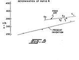
- Prior Art hydraulic lash adjusting tappets have minimum envelope requirements as dictated by the ratio of check valve ball diameter to plunger diameter. Measurements of several commercially available hydraulic lash adjusting tappets for production engines as shown in table I and Figure 5 have determined that the Prior Art devices have the ratio of check ball diameter to plunger diameter in excess of 0.3 4 5. The relationship of these parameters, as practiced in the known art makes it quite difficult to reduce the tappet size for.any given valve gear force load.
- the present invention provides an hydraulic lash adjuster for the valve gear of an internal combustion engine of the type employing a tappet guided for reciprocating movement in a precision bore in the engine.
- the lash adjusting tappet of the present invention preferably employs a roller follower mounted on the end thereof for contacting the lobe of the engine cam shaft.
- the hydraulic lash adjuster of the present invention is of the type intended to be supplied with a continuous supply of pressurized hydraulic fluid and particularly from the engine oil galleries.
- the lash adjuster of the present invention provides a unique construction whereby an existing hydraulic lash adjusting tappet for an engine valve gear having a friction face for contacting the cam lobe may be replaced with a tappet having a roller follower therein without the necessity for redesigning the valve gear to accommodate a larger tappet in order to include the roller follower.
- the hydraulic tappet of the present invention employs a reduced volume high pressure chamber for lash adjustment when compared with the tappet design practice heretofore known.
- the hydraulic tappet of the present invention employs a reduced diameter passage or orifice for supplying oil from the galleries or reservoir to the one-way ball check valve and a for supplying the high pressure chamber. The reduced diameter orifice permits a smaller check valve ball and consequently an axially shorter hydraulic pressure chamber and thus a more compact configuration.
- a tappet made in accordance with the present invention has the ratio "R" of the check ball diameter " D " to the diameter " ⁇ ” of the hydraulic plunger maintained less than 0.345.
- the reduced volume of the hydraulic fluid in the high pressure chamber increases the hydraulic stiffness of the tappet, such that, for a given valve gear load on the plunger a reduced amount of compression or shortening of length of the tappet is experienced in operation.
- the increased hydraulic stiffness, or reduced amount of compression of the tappet under load is attributed to the reduction in the amount of entrained air within the high pressure hydraulic chamber by virtue of the lower volume of hydraulic fluid containing such entrained air.
- the present invention thus provides a unique hydraulic lash adjuster enabling a compact design in which a roller follower may be employed; and, the hydraulic lash adjusting function of the tappet is improved.
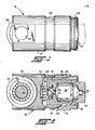
- the invention tappet is indicated generally at 10 and has a generally cylindrical body 12 with the outer cylinderical periphery thereof formed to precision dimensions for being slidably received in a guide bore in closely fitting relationship as is well known in the art.
- the body has a blind bore 14 provided in one end thereof in which is received a plunger 16 in precision sliding arrangement.
- the surfaces of the bore 14 and the cylindrical periphery of the plunger 16 are dimensioned with minimum clearance and tight tolerances to provide a precision fit to maintain a controlled leak-down of the hydraulic fluid in the tappet.
- a collector groove 18 is formed in the outer periphery of the plunger and, if desired, an optional corresponding shallow collector groove 20 may be provided in the wall of the body bore 14.
- the collector groove 18 is supplied by a passage 22 provided through the wall of the body and communicating with the exterior collector groove 24 provided on the outer periphery of the body.
- the plunger 16 is biased in a direction outwardly of the bore 14, or in a rightward direction in FIGURE 2, by a return spring 26 acting against the end of the plunger and the bottom 28 of the bore 14.
- the plunger is retained and limited in its outward movement by a suitable cap or spring clip 30 received over the flange 32 provided on the end of the body.
- the plunger 16 has a cavity 32 provided therein with the end thereof sealed by a plunger plug or cap 34 which is retained thereon in a suitable manner as for example by crimping,interference press fit or welding about the periphery thereof.
- the cap 34 and cavity 32 define a hydraulic fluid reservoir 33.
- the plunger cap 34 has a suitable orifice 36 provided in the end thereof which communicates with the reservoir 33 for supplying oil to an adjacent valve gear component, as for example, a rocker arm or push rod.
- the reservoir 33 is supplied by a passageway 36 provided through the wall of the plunger which is fed by communication with the collector grooves 18 and 20.
- the plunger has a fluid passage in the form of an orifice 38 provided in the end thereof which communicates with a counter bore 40 opening to the end of the tappet plunger.
- the shoulder of the orifice 38 and the bottom of the counter bore 40 form a valve seat.
- a check ball 42 received over the valve seat and is retained for limited movement therefrom by a cage 44 pressed into counter bore 40.
- a check ball spring 46 is registered against the underside of the cage and urges the check ball against the seat.
- the bottom and side walls of the body bore 28 and the end of the plunger 16 adjacent thereto thus provide the wall of a high pressure chamber 27 for retaining hydraulic fluid therein to provide the lash adjusting function of the tappet.
- An axle 48 is received transversely through the tappet body in a bore 50 formed therethrough adjacent the cam end of the tappet, and is retained therein by any suitable expedient as for example staking or welding.
- the body has a clearance recess or cutout 52 provided in the region surrounding the axle in which is received a suitable hardened roller follower 54 journaled over the axle on a suitable bearing arrangement such as the plurality of rollers 56 disposed about the axle.
- the tappet is received in a suitable guide bore in the engine and supplied with oil through a gallery communicating with passage 22.
- the oil passes directly through passage 36 and into the reservoir 33 for supplying the check valve 42 and supplying the other valve gear component through orifice 36.
- the roller follower 54 is in contact with the surface of a cam lobe (not shown) and the end of plug 34 contacts associated valve gear components (not shown) for transmitting the cyclically applied forces of the cam lobe opening and closing of the combustion chamber valves in the engine.
- One embodiment of a tappet employing the teachings of the present invention employs a diameter for check ball orifice 38 of 0.11" (2.8 mm), a plunger diameter of 0.615" (15.6 mm), a check ball 42 having a diameter of 0.156 inches (3.95mm) which provides a D/ ⁇ ratio "R" equal 0.254.
- the diameter ⁇ of the plunger is found from the graph directly. Having determined the plunger diameter ⁇ , the residual hydraulic chamber volume V may be determined with reference to Fig. 4. It will be understood that the residual hydraulic chamber volume V (in3) is the volume of the hydraulic chamber 27 with the plunger 16 "bottomed out” or in the furthest leftward displaced position, as shown in solid outline in Fig. 2 for the plunger end plug 34.
- the graph in FIGURE 4 is entered for a known permissible amount of plunger displacement, or tolerable lost motion in the valve gear, to determine the value of the ratio of the residual high pressure chamber volume V.
- the ratio V/ TT/4 ⁇ 2 high pressure chamber volume V to plunger area known the residual chamber volume V is readily computed.
- the dimensions of the parts of the tappet are established to provide the desired value V, by suitable procedures, as will be known to those skilled in the art with the understanding that the tappet plunger diameter is fixed at the value of ⁇ as already determined by the above described procedure.
- the ratio R of the check ball diameter D, to plunger diameter ⁇ is obtained by entering the lower plot line of the graph at the appropriate value of V/ ⁇ /4 ⁇ 2 .
- the lowest plotted point on the plot line of Fig. 5 represents the values for the present tappet form from Table I.
- the present invention provides a unique hydraulic lash adjusting tappet having a reduced volume high pressure hydraulic fluid chamber for lash adjustment which permits the tappet to have a foreshortened and compact envelope. Furthermore, tappets made in accordance with the present inventions exhibit an increased longitudinal stiffness and resistance to compression under applied forces from the adjacent engine valve gear components.
- the present invention provides this improved lash adjustment function by the unique and novel and structural arrangement wherein the ratio of the diameter of the check valve ball diameter to the hydraulic plunger diameter is maintained less than 0.345.
- the reduced diameter orifice permits a smaller check valve ball to be employed and thus further improves the compactness of the tappet.
- the compactness is particularly important where it is desired to replace an existing friction faced tappet with a tappet having a roller follower without increasing the envelope of the tappet.
Landscapes
- Engineering & Computer Science (AREA)
- Mechanical Engineering (AREA)
- General Engineering & Computer Science (AREA)
- Valve-Gear Or Valve Arrangements (AREA)
Applications Claiming Priority (2)
| Application Number | Priority Date | Filing Date | Title |
|---|---|---|---|
| US69512885A | 1985-01-25 | 1985-01-25 | |
| US695128 | 1985-01-25 |
Publications (1)
| Publication Number | Publication Date |
|---|---|
| EP0190418A1 true EP0190418A1 (fr) | 1986-08-13 |
Family
ID=24791694
Family Applications (1)
| Application Number | Title | Priority Date | Filing Date |
|---|---|---|---|
| EP85114781A Withdrawn EP0190418A1 (fr) | 1985-01-25 | 1985-11-21 | Dispositif hydraulique de rattrapage de jeu |
Country Status (1)
| Country | Link |
|---|---|
| EP (1) | EP0190418A1 (fr) |
Cited By (7)
| Publication number | Priority date | Publication date | Assignee | Title |
|---|---|---|---|---|
| EP0604598A4 (en) * | 1992-04-24 | 1994-07-27 | Cummins Engine Co Inc | Mechanically retained wear-resistant ceramic pad. |
| DE19630443A1 (de) * | 1996-07-27 | 1998-01-29 | Schaeffler Waelzlager Kg | Hydraulisches Spielausgleichselement |
| DE102009036775A1 (de) * | 2009-08-08 | 2011-02-10 | Schaeffler Technologies Gmbh & Co. Kg | Steuertrieb einer Brennkraftmaschine |
| DE102009036778A1 (de) * | 2009-08-08 | 2011-02-10 | Schaeffler Technologies Gmbh & Co. Kg | Steuertrieb einer Brennkraftmaschine |
| CN102588026A (zh) * | 2011-01-12 | 2012-07-18 | 谢夫勒科技股份两合公司 | 滚子凸轮从动件 |
| EP2853698A1 (fr) * | 2013-09-27 | 2015-04-01 | Aktiebolaget SKF | Poussoir de came, pompe à injection et actionneur de soupape comportant un tel poussoir de came et procédé de fabrication |
| WO2015191663A1 (fr) | 2014-06-10 | 2015-12-17 | Jacobs Vehicle Systems, Inc. | Liaison entre une source de mouvement auxiliaire et un trajet de charge de mouvement principal dans un moteur à combustion interne |
Citations (2)
| Publication number | Priority date | Publication date | Assignee | Title |
|---|---|---|---|---|
| US2742030A (en) * | 1953-06-26 | 1956-04-17 | Thompson Prod Inc | Automatic clearance adapter |
| DE2941495A1 (de) * | 1978-11-01 | 1980-05-14 | Gen Motors Corp | Ventilstoessel mit mitnehmerrolle |
-
1985
- 1985-11-21 EP EP85114781A patent/EP0190418A1/fr not_active Withdrawn
Patent Citations (2)
| Publication number | Priority date | Publication date | Assignee | Title |
|---|---|---|---|---|
| US2742030A (en) * | 1953-06-26 | 1956-04-17 | Thompson Prod Inc | Automatic clearance adapter |
| DE2941495A1 (de) * | 1978-11-01 | 1980-05-14 | Gen Motors Corp | Ventilstoessel mit mitnehmerrolle |
Cited By (16)
| Publication number | Priority date | Publication date | Assignee | Title |
|---|---|---|---|---|
| EP0604598A4 (en) * | 1992-04-24 | 1994-07-27 | Cummins Engine Co Inc | Mechanically retained wear-resistant ceramic pad. |
| US5435234A (en) * | 1992-04-24 | 1995-07-25 | Cummins Engine Co., Inc. | Mechanically retained wear-resistant ceramic pad |
| DE19630443A1 (de) * | 1996-07-27 | 1998-01-29 | Schaeffler Waelzlager Kg | Hydraulisches Spielausgleichselement |
| US5787850A (en) * | 1996-07-27 | 1998-08-04 | Ina Walzlager Schaeffler Kg | Hydraulic clearance compensation element |
| CN101994534B (zh) * | 2009-08-08 | 2014-07-23 | 谢夫勒科技股份两合公司 | 内燃机的控制传动装置 |
| DE102009036778A1 (de) * | 2009-08-08 | 2011-02-10 | Schaeffler Technologies Gmbh & Co. Kg | Steuertrieb einer Brennkraftmaschine |
| CN101994534A (zh) * | 2009-08-08 | 2011-03-30 | 谢夫勒科技有限两合公司 | 内燃机的控制传动装置 |
| DE102009036775A1 (de) * | 2009-08-08 | 2011-02-10 | Schaeffler Technologies Gmbh & Co. Kg | Steuertrieb einer Brennkraftmaschine |
| CN102588026A (zh) * | 2011-01-12 | 2012-07-18 | 谢夫勒科技股份两合公司 | 滚子凸轮从动件 |
| CN102588026B (zh) * | 2011-01-12 | 2016-07-06 | 舍弗勒技术股份两合公司 | 滚子凸轮从动件 |
| EP2853698A1 (fr) * | 2013-09-27 | 2015-04-01 | Aktiebolaget SKF | Poussoir de came, pompe à injection et actionneur de soupape comportant un tel poussoir de came et procédé de fabrication |
| US9541184B2 (en) | 2013-09-27 | 2017-01-10 | Aktiebolaget Skf | Mechanical system, injection pump and valve actuator comprising such a mechanical system and manufacturing method |
| WO2015191663A1 (fr) | 2014-06-10 | 2015-12-17 | Jacobs Vehicle Systems, Inc. | Liaison entre une source de mouvement auxiliaire et un trajet de charge de mouvement principal dans un moteur à combustion interne |
| US10626763B2 (en) | 2014-06-10 | 2020-04-21 | Jacobs Vehicle Systems, Inc. | Linkage between an auxiliary motion source and a main motion load path in an internal combustion engine |
| EP3653851A1 (fr) | 2014-06-10 | 2020-05-20 | Jacobs Vehicle Systems, Inc. | Liaison entre une source de mouvement auxiliaire et un trajet de charge de mouvement principal dans un moteur à combustion interne |
| US11313259B2 (en) | 2014-06-10 | 2022-04-26 | Jacobs Vehicle Systems, Inc. | Linkage between an auxiliary motion source and a main motion load path in an internal combustion engine |
Similar Documents
| Publication | Publication Date | Title |
|---|---|---|
| US4924821A (en) | Hydraulic lash adjuster and bridge assembly | |
| US5566652A (en) | Light weight cam follower | |
| US5361733A (en) | Compact valve lifters | |
| US5090364A (en) | Two-step valve operating mechanism | |
| US4089234A (en) | Anti-rotating guide for reciprocating members | |
| EP0615056B1 (fr) | Poussoir de soupape à galet | |
| US4098240A (en) | Valve gear and lash adjustment means for same | |
| US4191142A (en) | Self-contained hydraulic lash adjuster | |
| US4228771A (en) | Lash adjustment means for valve gear of an internal combustion engine | |
| US3509858A (en) | Overhead cam valve lifter | |
| US4807576A (en) | Hydraulic lash adjuster for use in valve operating mechanism | |
| US5901676A (en) | Hydraulic lash compensator | |
| EP0030781A1 (fr) | Poussoir hydraulique pour vanne à entrainement direct | |
| US4711202A (en) | Direct acting cam-valve assembly | |
| EP2183468B1 (fr) | Dispositif de compensation de jeu hydraulique avec élément de perte de levage mécanique | |
| US4633827A (en) | Hydraulic lash adjuster with combined reservoir extension and metering system | |
| US4462364A (en) | Hydraulic lash adjuster | |
| US5642694A (en) | Integral formed oil column extender for hydraulic lash adjuster | |
| US4338894A (en) | Self-contained hydraulic lash adjuster | |
| EP0190418A1 (fr) | Dispositif hydraulique de rattrapage de jeu | |
| EP0743473A1 (fr) | Tendeur hydraulique autonome de courroie | |
| US5862785A (en) | Hydraulic lash adjuster and improved oil flow path therefor | |
| US3704696A (en) | Hydraulic valve lifter | |
| EP0623190B1 (fr) | Poussoir a compensation hydraulique du jeu de soupape et piston libre | |
| US4009696A (en) | Hydraulic lash adjuster with internal oil pressure control |
Legal Events
| Date | Code | Title | Description |
|---|---|---|---|
| PUAI | Public reference made under article 153(3) epc to a published international application that has entered the european phase |
Free format text: ORIGINAL CODE: 0009012 |
|
| 17P | Request for examination filed |
Effective date: 19860411 |
|
| AK | Designated contracting states |
Kind code of ref document: A1 Designated state(s): DE GB IT |
|
| STAA | Information on the status of an ep patent application or granted ep patent |
Free format text: STATUS: THE APPLICATION IS DEEMED TO BE WITHDRAWN |
|
| 18D | Application deemed to be withdrawn |
Effective date: 19870214 |
|
| RIN1 | Information on inventor provided before grant (corrected) |
Inventor name: BUENTE, STEPHEN MARK |