EP0190509A2 - Générateur d'impulsions - Google Patents
Générateur d'impulsions Download PDFInfo
- Publication number
- EP0190509A2 EP0190509A2 EP85309517A EP85309517A EP0190509A2 EP 0190509 A2 EP0190509 A2 EP 0190509A2 EP 85309517 A EP85309517 A EP 85309517A EP 85309517 A EP85309517 A EP 85309517A EP 0190509 A2 EP0190509 A2 EP 0190509A2
- Authority
- EP
- European Patent Office
- Prior art keywords
- capacitor
- switch
- charge
- inductor
- recharging
- Prior art date
- Legal status (The legal status is an assumption and is not a legal conclusion. Google has not performed a legal analysis and makes no representation as to the accuracy of the status listed.)
- Withdrawn
Links
- 239000003990 capacitor Substances 0.000 claims abstract description 58
- 238000007599 discharging Methods 0.000 claims abstract description 4
- 101000668165 Homo sapiens RNA-binding motif, single-stranded-interacting protein 1 Proteins 0.000 claims description 14
- 102100039692 RNA-binding motif, single-stranded-interacting protein 1 Human genes 0.000 claims description 14
- 230000005611 electricity Effects 0.000 claims description 3
- 238000001514 detection method Methods 0.000 claims description 2
- 238000000034 method Methods 0.000 claims 1
- 101100365087 Arabidopsis thaliana SCRA gene Proteins 0.000 description 10
- 101150105073 SCR1 gene Proteins 0.000 description 10
- 101100134054 Saccharomyces cerevisiae (strain ATCC 204508 / S288c) NTG1 gene Proteins 0.000 description 10
- 101000668170 Homo sapiens RNA-binding motif, single-stranded-interacting protein 2 Proteins 0.000 description 7
- 102100039690 RNA-binding motif, single-stranded-interacting protein 2 Human genes 0.000 description 7
- 230000001960 triggered effect Effects 0.000 description 4
- 208000019300 CLIPPERS Diseases 0.000 description 2
- 208000021930 chronic lymphocytic inflammation with pontine perivascular enhancement responsive to steroids Diseases 0.000 description 2
- 238000010586 diagram Methods 0.000 description 2
- 230000000694 effects Effects 0.000 description 2
- 239000007787 solid Substances 0.000 description 1
Images

Classifications
-
- H—ELECTRICITY
- H03—ELECTRONIC CIRCUITRY
- H03K—PULSE TECHNIQUE
- H03K3/00—Circuits for generating electric pulses; Monostable, bistable or multistable circuits
- H03K3/02—Generators characterised by the type of circuit or by the means used for producing pulses
- H03K3/53—Generators characterised by the type of circuit or by the means used for producing pulses by the use of an energy-accumulating element discharged through the load by a switching device controlled by an external signal and not incorporating positive feedback
- H03K3/57—Generators characterised by the type of circuit or by the means used for producing pulses by the use of an energy-accumulating element discharged through the load by a switching device controlled by an external signal and not incorporating positive feedback the switching device being a semiconductor device
Definitions
- This invention relates to a pulse generator of the type comprising a capacitor, means for periodically discharging the capacitor to generate pulses of electricity and means for recharging the capacitor between pulses.
- the invention was particularly developed for use in supplying pulses to a microwave tube such as a magnetron in a radar transmitter.
- the capacitor can develop a reverse charge under fault conditions usually related to sparking in the tube.
- This reverse charge can vary from a small inconsequencial value up to a value equal to the original forward charge. Large reverse charges can present a problem because they can lead to damaging transients which lead to circuit failure.
- This invention arose with a view to obviating the aforementioned difficulties and provides, in a pulse generator of the aforementioned type, means for sensing a residual reverse polarity charge on the capacitor after generation of a pulse and for using the energy stored in it to assist in recharging the capacitor for the next pulse.
- the means for recharging the capacitor will normally include a D.C. supply connected to the capacitor via a series inductor to control the current demand from the D.C. supply.
- the means for using the stored energy in the reverse charged capacitor to recharge it preferably includes an inductor and a switch for connecting the inductor across the capacitor.
- the switch is closed in response to detection of a reverse polarity of more than a particular amount so that the energy in the reverse charged capacitor commences to recharge it through the inductor in the forward direction.
- the abovementioned switch may then be opened and a second switch closed to connect a D.C. supply to the capacitor through the aforementioned inductor to ensure that the capacitor is fully recharged to a required value.
- the aforementioned inductor is preferably the primary of a transformer whose secondary is connected to a charging regulator circuit e.g., following known design principles. It is a characteristic of charging regulators that they do not operate satisfactorily with a large reverse voltage on the capacitor. Thus an added benefit of the invention is that this charging regulator, if included as is preferred, is not subjected to such conditions.
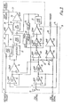
- the circuit shown in Figure 1 comprises a load 1 consisting of a magnetron and pulse transformer. This is driven by pulses of electricity from a capacitor 2 and switch 3.
- a D.C. voltage supply 4 charges the capacitor 2 through inductor L2, switch SCR1, and inductor Ll forming the primary of a transformer 5.
- switch SCR1 When the capacitor 2 is fully charged the switch SCR1 is opened before the next pulse is produced by closing of switch 3.
- the maximum voltage to which the capacitor 2 is charged is controlled by a circuit comprising transformer secondary L3 and switch SCR3.
- SCR3 At a predetermined time SCR3 is triggered to arrest charging of the capacitor 2 at the desired voltage, the excess energy in inductor Ll being diverted back to the D.C. supply 4.
- SCR3 When SCR3 is closed the charge on the capacitor 2 is delivered to the load and under normal conditions the residual charge left on capacitor 2 is of little consequence to normal operation.
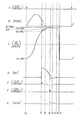
- the PFN now starts to co-sinusoidally reverse aiming at Enf as shown at C on Figure 2 with a half sine wave of current of peak value En REV Cn/Ll.
- SCR1 is fired as shown at E on Figure 2 at a voltage corresponding to En Trig as shown at C on Figure 2.
- This action simultaneously turns off SCR2 and connects the D.C. supply 4 in series with Ll and capacitor 2.
- the current is of clipped sine form with a peak value equal to that of the current that was flowing in SCR2 at time tl. This current as shown at D on Figure 2 would reach zero at time t4.
- the effective current delivered by the D.C. supply 4 and shown at D on Figure 2 is in fact the difference between normal energy and the reversed energy with due allowance for circuit losses.
- the bulk of the forward energy in the capacitor is recovered from the reversed energy caused by the load short circuit fault conditions.
- the inductor L2 in series with SCR1 is to prevent too rapid a turn off of SCR2 when SCRl is triggered on as this can damage SCR1 and/or SCR2.
- the impedances shown as Z across SCR1 and SCR2 will usually be required to clamp excess ringing during turn off of SCR's.
- Such impedances are usually known as 'snubbers' and they are specified to damp out the effects of stray inductance and capacitance. However correctly designed the effects of L2 and resistors Z will be barely detectable on correct circuit operation.
- a manual control 10 is adjusted to provide a reference voltage at 11 which is fed into a unity gain amplifier 12 and then to an amplifier 13 having a gain of -O.5 in this example. This value establishes the degree of reversal of the voltage on capacitor 2 at which a fault condition is defined as existing.
- a measure of the voltage on capacitor C, from the potential divider 6, 7 is applied on line 14 to a unity gain buffer amplifier 15 and thence to comparator 16 where it is compared with the reference voltage from 13.
- comparator 16 When no fault condition applies the output of comparator 16 stays low.
- the output of invertor 17 is high, enabling AND gate 18 to pass a recharge trigger when appearing at 9.
- This recharge trigger is fed via OR gate.19 and amplifer 20 to line 21 where it provides the trigger for switch SCR1.
- the recharge trigger at 9 is under no fault conditions, fed directly to SCR1.
- After triggering of SCR1 recharging of capacitor 2 commences and the voltage on line 14 rises. This is applied via 15 and a potential divider 22 and 23 to comparator 24 which also receives the output of unity gain buffer 12.
- comparator output 24 goes high and is applied to the gate of SCR3 via amplifier 25 and line 26.
- comparator 33 output goes high and passes via an AND gate 31 OR gate 19, amplifer 20 and line 21 to the gate of SCR1 to complete the recharging of capacitor 2 which is brought to precisely the required voltage by the operation of the regulator system 22. to 26 as previously described.
- AND gate 31 is fed via delay 34 to reset bistable 30 and thus returns sample and hold amplifier 32 to its sample mode and disenables AND gate 31.
Landscapes
- Generation Of Surge Voltage And Current (AREA)
Applications Claiming Priority (2)
| Application Number | Priority Date | Filing Date | Title |
|---|---|---|---|
| GB08502480A GB2170667B (en) | 1985-01-31 | 1985-01-31 | A pulse generator |
| GB8502480 | 1985-01-31 |
Publications (2)
| Publication Number | Publication Date |
|---|---|
| EP0190509A2 true EP0190509A2 (fr) | 1986-08-13 |
| EP0190509A3 EP0190509A3 (fr) | 1988-09-28 |
Family
ID=10573735
Family Applications (1)
| Application Number | Title | Priority Date | Filing Date |
|---|---|---|---|
| EP85309517A Withdrawn EP0190509A3 (fr) | 1985-01-31 | 1985-12-30 | Générateur d'impulsions |
Country Status (4)
| Country | Link |
|---|---|
| US (1) | US4803378A (fr) |
| EP (1) | EP0190509A3 (fr) |
| ES (1) | ES8706297A1 (fr) |
| GB (1) | GB2170667B (fr) |
Cited By (2)
| Publication number | Priority date | Publication date | Assignee | Title |
|---|---|---|---|---|
| EP0465065A3 (en) * | 1990-06-22 | 1992-05-13 | Varian Associates, Inc. | Circuit for coupling energy to pulse forming network or capacitor |
| WO2020142956A1 (fr) * | 2019-01-09 | 2020-07-16 | 深圳市大疆创新科技有限公司 | Circuit de décharge destiné à un dispositif de mesure de distance, système radar distribué et plateforme mobile |
Families Citing this family (27)
| Publication number | Priority date | Publication date | Assignee | Title |
|---|---|---|---|---|
| GB2220603B (en) * | 1988-05-27 | 1992-01-29 | Nada Electronics Ltd | Control circuit for electric discharge machining |
| FR2654876B1 (fr) * | 1989-11-23 | 1993-11-12 | Commissariat A Energie Atomique | Dispositif de charge de moyens d'accumulation d'energie electrique, muni de moyens permettant de maitriser cette charge. |
| US5086383A (en) * | 1991-04-30 | 1992-02-04 | Elco Co., Ltd. | Step-up power supplying circuit |
| US5291143A (en) * | 1992-03-09 | 1994-03-01 | United Technologies Corporation | Modulator with improved damping |
| US5347209A (en) * | 1992-08-21 | 1994-09-13 | The United States Of America As Represented By The United States Department Of Energy | Voltage control in pulsed system by predict-ahead control |
| US5567995A (en) * | 1994-10-20 | 1996-10-22 | The United States Of America As Represented By The Secretary Of The Air Force | Multi winding spiral generator |
| US5790023A (en) * | 1994-12-22 | 1998-08-04 | Waters Instruments Inc. | Apparatus and method for control of electric fence |
| CA2186899C (fr) * | 1995-02-17 | 2010-04-20 | Daniel L. Birx | Circuit generateur pulse en puissance avec recuperation de l'energie |
| US5691629A (en) * | 1995-07-13 | 1997-11-25 | The United States Of America As Represented By The Secretary Of The Air Force | Non-volatile power supply having energy efficient DC/DC voltage converters with a small storage capacitor |
| US6023638A (en) | 1995-07-28 | 2000-02-08 | Scimed Life Systems, Inc. | System and method for conducting electrophysiological testing using high-voltage energy pulses to stun tissue |
| US5721391A (en) * | 1996-08-26 | 1998-02-24 | The United States Of America As Represented By The Secretary Of The Navy | Electronic firing circuit |
| US5914974A (en) * | 1997-02-21 | 1999-06-22 | Cymer, Inc. | Method and apparatus for eliminating reflected energy due to stage mismatch in nonlinear magnetic compression modules |
| US5940421A (en) * | 1997-12-15 | 1999-08-17 | Cymer, Inc. | Current reversal prevention circuit for a pulsed gas discharge laser |
| US6151346A (en) * | 1997-12-15 | 2000-11-21 | Cymer, Inc. | High pulse rate pulse power system with fast rise time and low current |
| US6107699A (en) * | 1998-05-22 | 2000-08-22 | Scimed Life Systems, Inc. | Power supply for use in electrophysiological apparatus employing high-voltage pulses to render tissue temporarily unresponsive |
| US6428537B1 (en) | 1998-05-22 | 2002-08-06 | Scimed Life Systems, Inc. | Electrophysiological treatment methods and apparatus employing high voltage pulse to render tissue temporarily unresponsive |
| US6618421B2 (en) * | 1998-07-18 | 2003-09-09 | Cymer, Inc. | High repetition rate gas discharge laser with precise pulse timing control |
| US6477193B2 (en) | 1998-07-18 | 2002-11-05 | Cymer, Inc. | Extreme repetition rate gas discharge laser with improved blower motor |
| US6442181B1 (en) | 1998-07-18 | 2002-08-27 | Cymer, Inc. | Extreme repetition rate gas discharge laser |
| KR100276020B1 (ko) * | 1998-08-19 | 2001-01-15 | 윤문수 | 비선형 커패시터를 이용한 고압펄스발생 장치 |
| US6066901A (en) * | 1998-09-17 | 2000-05-23 | First Point Scientific, Inc. | Modulator for generating high voltage pulses |
| US6763049B1 (en) * | 2000-06-15 | 2004-07-13 | Lambda Emi | Very high repetition rate power supply system and method |
| GB2378327A (en) * | 2001-06-15 | 2003-02-05 | Marconi Applied Technologies | Electrical circuit protection system |
| AU2003243515A1 (en) * | 2002-06-13 | 2003-12-31 | Pei Electronics, Inc. | Improved pulse forming converter |
| US7151330B2 (en) * | 2003-03-20 | 2006-12-19 | Radiance Technologies, Inc. | Apparatus and method for generating high voltages using a voltage inversion generator and multiple closed-path ferrites |
| US7199560B2 (en) * | 2004-11-05 | 2007-04-03 | Linear Technology Corporation | Switch-mode power supply voltage regulator and methodology |
| FR3055973B1 (fr) * | 2016-09-15 | 2020-01-03 | Thales | Emetteur radar muni d'au moins un tube hyperfrequence |
Family Cites Families (25)
| Publication number | Priority date | Publication date | Assignee | Title |
|---|---|---|---|---|
| US3171040A (en) * | 1961-01-16 | 1965-02-23 | Gen Dynamics Corp | Fast charging circuit for pulse networks |
| FR1297338A (fr) * | 1961-05-19 | 1962-06-29 | Schlumberger Prospection | Générateur déclenché d'oscillations électriques |
| US3263099A (en) * | 1962-05-25 | 1966-07-26 | Gen Electric | Power amplifier circuit |
| US3139585A (en) * | 1962-06-26 | 1964-06-30 | Ling Temco Vought Inc | Voltage controlling circuit for line type modulator with means feeding back excess power to source |
| GB1053656A (fr) * | 1963-10-16 | 1900-01-01 | ||
| US3296551A (en) * | 1965-08-09 | 1967-01-03 | John P Staples | Solid state modulator circuit for selectively providing different pulse widths |
| US3374443A (en) * | 1965-09-27 | 1968-03-19 | Gen Dynamics Corp | Pulse generator for modulating a magnetron |
| DE1613338C3 (de) * | 1966-07-30 | 1978-10-26 | Honeywell Information Systems Italia S.P.A., Caluso, Turin (Italien) | Gleichspannungswandler |
| US3486043A (en) * | 1966-12-12 | 1969-12-23 | Sylvania Electric Prod | High power pulse width modulator employing step recovery diodes |
| US3518527A (en) * | 1968-05-01 | 1970-06-30 | Basic Inc | Scr power supply with inherent line regulating feature |
| US3567996A (en) * | 1969-01-02 | 1971-03-02 | Ransburg Electric Coating Corp | Regulated high voltage,direct current power supply useable with an electrostatic coating device |
| US3671761A (en) * | 1970-01-22 | 1972-06-20 | Nippon Electric Co | Single pulse generating circuit |
| US3641422A (en) * | 1970-10-01 | 1972-02-08 | Robert P Farnsworth | Wide band boost regulator power supply |
| US3655994A (en) * | 1971-02-08 | 1972-04-11 | Wire Sales Co | Electric fence charger |
| US3675116A (en) * | 1971-03-15 | 1972-07-04 | Raytheon Co | Improvement in resonant charging circuit |
| FR2133206A5 (fr) * | 1971-04-13 | 1972-11-24 | Comp Generale Electricite | |
| US3849670A (en) * | 1973-04-13 | 1974-11-19 | Webster Electric Co Inc | Scr commutation circuit for current pulse generators |
| US3928809A (en) * | 1974-05-06 | 1975-12-23 | Whittaker Corp | Pulse width control system |
| US3931528A (en) * | 1974-08-23 | 1976-01-06 | Hughes Aircraft Company | Pulse generator for reactive loads |
| DK157280C (da) * | 1977-09-13 | 1990-04-30 | Gallagher Electronics Ltd | Spaendingskilde til elektriske hegn |
| US4150307A (en) * | 1977-09-23 | 1979-04-17 | International Telephone And Telegraph Corporation | Line modulator nondissipative series regulator |
| CH622658A5 (fr) * | 1977-10-27 | 1981-04-15 | Hoffmann La Roche | |
| AT374637B (de) * | 1980-12-15 | 1984-05-10 | Zumtobel Ag | Schaltungsanordnung zum betrieb einer last aus einem wechselstromnetz |
| US4404476A (en) * | 1981-09-24 | 1983-09-13 | General Electric Company | Pulse shaping and amplifying circuit |
| IE55329B1 (en) * | 1984-02-22 | 1990-08-15 | David Reynolds Gray | A high voltage pulse generator |
-
1985
- 1985-01-31 GB GB08502480A patent/GB2170667B/en not_active Expired
- 1985-12-30 EP EP85309517A patent/EP0190509A3/fr not_active Withdrawn
-
1986
- 1986-01-28 US US06/823,451 patent/US4803378A/en not_active Expired - Fee Related
- 1986-01-30 ES ES551419A patent/ES8706297A1/es not_active Expired
Cited By (2)
| Publication number | Priority date | Publication date | Assignee | Title |
|---|---|---|---|---|
| EP0465065A3 (en) * | 1990-06-22 | 1992-05-13 | Varian Associates, Inc. | Circuit for coupling energy to pulse forming network or capacitor |
| WO2020142956A1 (fr) * | 2019-01-09 | 2020-07-16 | 深圳市大疆创新科技有限公司 | Circuit de décharge destiné à un dispositif de mesure de distance, système radar distribué et plateforme mobile |
Also Published As
| Publication number | Publication date |
|---|---|
| US4803378A (en) | 1989-02-07 |
| GB2170667A (en) | 1986-08-06 |
| ES551419A0 (es) | 1987-06-01 |
| GB8502480D0 (en) | 1985-03-06 |
| ES8706297A1 (es) | 1987-06-01 |
| GB2170667B (en) | 1988-09-07 |
| EP0190509A3 (fr) | 1988-09-28 |
Similar Documents
| Publication | Publication Date | Title |
|---|---|---|
| US4803378A (en) | Pulse generator | |
| US5436786A (en) | Isolator surge protector for DC isolation and AC grounding of cathodically protected systems | |
| US3617851A (en) | Battery charger with control circuit for cyclical charge and discharge as a function of battery voltage during discharge | |
| US4070699A (en) | Charging circuits using controlled magnetic fields | |
| US5083093A (en) | Circuit for coupling energy to pulse forming network or capacitor | |
| US5402058A (en) | Method and apparatus for controlling discharge of a thyristor-switched capacitor | |
| US3900786A (en) | High voltage pulse generating circuit | |
| US4405889A (en) | Power supply for repetitive discharge apparatus | |
| US4076974A (en) | Current control device and method | |
| KR960003201B1 (ko) | 이상전압 검출 제어장치 | |
| US4774449A (en) | Transformerless battery charger in combination with a battery, and method of charging a battery | |
| US5337228A (en) | Differential charging circuit | |
| US3683256A (en) | High-current apparatus for charging batteries | |
| US4069449A (en) | Flyback type power supply | |
| US4031451A (en) | Charging circuit with SCR's triggered by pedestal and cosine modified ramp unijunction circuit having means for current limiting by controlling pedestal level | |
| US4065805A (en) | Circuit arrangement in an electrical device operated with direct-current, especially in a timing relay | |
| US3781632A (en) | Series type solid state voltage regulator which provides constant voltage to a storage device | |
| US3475651A (en) | Charging and triggering circuits for pulsed electrical devices such as flash lamps | |
| US3867684A (en) | Pulse forming network charging control system | |
| US3656046A (en) | Power conversion system | |
| GB2155709A (en) | Battery charging | |
| EP0161109A2 (fr) | Chargeur de batterie | |
| US3683257A (en) | Apparatus for charging batteries | |
| US5528180A (en) | Steerable pulse phase controller | |
| US3699399A (en) | Circuits for controlling solenoid energization to reduce heating |
Legal Events
| Date | Code | Title | Description |
|---|---|---|---|
| PUAI | Public reference made under article 153(3) epc to a published international application that has entered the european phase |
Free format text: ORIGINAL CODE: 0009012 |
|
| AK | Designated contracting states |
Kind code of ref document: A2 Designated state(s): DE FR IT NL SE |
|
| PUAL | Search report despatched |
Free format text: ORIGINAL CODE: 0009013 |
|
| AK | Designated contracting states |
Kind code of ref document: A3 Designated state(s): DE FR IT NL SE |
|
| 17P | Request for examination filed |
Effective date: 19881105 |
|
| 17Q | First examination report despatched |
Effective date: 19900601 |
|
| STAA | Information on the status of an ep patent application or granted ep patent |
Free format text: STATUS: THE APPLICATION IS DEEMED TO BE WITHDRAWN |
|
| 18D | Application deemed to be withdrawn |
Effective date: 19910403 |
|
| RIN1 | Information on inventor provided before grant (corrected) |
Inventor name: RICHARDSON, ROBERT |