EP0190535B1 - Dispositif pour protéger la zone d'insertion du fil de trame contre les duvets dans un métier à tisser - Google Patents
Dispositif pour protéger la zone d'insertion du fil de trame contre les duvets dans un métier à tisser Download PDFInfo
- Publication number
- EP0190535B1 EP0190535B1 EP85810042A EP85810042A EP0190535B1 EP 0190535 B1 EP0190535 B1 EP 0190535B1 EP 85810042 A EP85810042 A EP 85810042A EP 85810042 A EP85810042 A EP 85810042A EP 0190535 B1 EP0190535 B1 EP 0190535B1
- Authority
- EP
- European Patent Office
- Prior art keywords
- weft
- plate
- flight
- shielding
- weft thread
- Prior art date
- Legal status (The legal status is an assumption and is not a legal conclusion. Google has not performed a legal analysis and makes no representation as to the accuracy of the status listed.)
- Expired
Links
- 230000037431 insertion Effects 0.000 title description 13
- 238000003780 insertion Methods 0.000 title description 13
- 235000014676 Phragmites communis Nutrition 0.000 claims description 11
- 238000004140 cleaning Methods 0.000 claims description 10
- 238000012216 screening Methods 0.000 claims 8
- 230000000717 retained effect Effects 0.000 claims 1
- 238000009941 weaving Methods 0.000 description 20
- 239000004744 fabric Substances 0.000 description 8
- 238000005299 abrasion Methods 0.000 description 3
- 230000001133 acceleration Effects 0.000 description 3
- 230000035508 accumulation Effects 0.000 description 2
- 238000009825 accumulation Methods 0.000 description 2
- 230000000694 effects Effects 0.000 description 2
- 230000007246 mechanism Effects 0.000 description 2
- 239000002245 particle Substances 0.000 description 2
- 230000009467 reduction Effects 0.000 description 2
- 239000000654 additive Substances 0.000 description 1
- 230000005540 biological transmission Effects 0.000 description 1
- 238000005352 clarification Methods 0.000 description 1
- 230000007547 defect Effects 0.000 description 1
- 238000005265 energy consumption Methods 0.000 description 1
- 239000000835 fiber Substances 0.000 description 1
- 239000012535 impurity Substances 0.000 description 1
- 230000003993 interaction Effects 0.000 description 1
- 238000007790 scraping Methods 0.000 description 1
- 238000009423 ventilation Methods 0.000 description 1
Images


Classifications
-
- D—TEXTILES; PAPER
- D03—WEAVING
- D03J—AUXILIARY WEAVING APPARATUS; WEAVERS' TOOLS; SHUTTLES
- D03J1/00—Auxiliary apparatus combined with or associated with looms
- D03J1/002—Climatic conditioning or removing lint or dust
Definitions
- the invention relates to a device for shielding against flight in the inlet area of the weft thread of a weaving machine.
- the infeed area of the weft thread or the weft threads in multi-color weaving machines extends from the weft yarn bobbins via possibly arranged intermediate stores for the weft threads and the weft insertion means, e.g. a projectile or an air jet until it enters the shed formed by the warp threads.
- Numerous devices for cleaning the infeed area of weft threads in weaving machines have therefore been developed with the aim of removing the flight that has accumulated on machine parts or preventing flight from accumulating at all. It is e.g. to blow-off and / or suction devices, which are either attached to individual weaving machines or move individually back and forth over groups of weaving machines.
- Such devices equipped with swivel nozzles are known, for example, from DE-PS 15 35 894, which corresponds to US-A-3 429 746, DE-OS 19 19 229 or from US-PS 2 798 825.
- the object of this invention is to provide a device which is as simple and effective as possible for preventing flight accumulation and the further transport of flight pads in the infeed area of the weft thread of weaving machines, which has a self-cleaning effect.
- the invention characterized in the claims solves the problem in that a device for shielding against flight is arranged in the inlet region of the weft thread with at least one shielding plate with a passage opening for the weft insertion means and the weft thread, characterized in that at least one first shielding plate is assigned a second shielding plate and at least one of the parts assigned to one another is movable relative to the other, the second shielding plate being designed as a cleaning element for the first plate.
- the advantages of the invention compared to the prior art can be seen in the fact that the flight which is also transported is stripped off after striking the shielding plate by the aforementioned relative movement to the cleaning element and is therefore not entered into the shed.
- the flight can thus be carried out without additional complex measures such as Blowers fall into the interior of the weaving machine, from where it e.g. can be sucked off the weaving chain together with the flight.
- Blowers fall into the interior of the weaving machine, from where it e.g. can be sucked off the weaving chain together with the flight.
- Blowers fall into the interior of the weaving machine, from where it e.g. can be sucked off the weaving chain together with the flight.
- the dimensions of the device according to the invention can be kept smaller compared to known devices, which means that fewer handicaps occur for the staff when maintaining a weaving machine.
- the invention can be used particularly advantageously, e.g.
- the passage opening can be reduced in size in a simple manner after the projectile has passed through the shield, so that the weft thread can still pass through unhindered, but no flight cushions in the vicinity of the weft thread find your way through the opening.
- the weft bobbin 1, the weft 2 and, as a weft insertion means, the projectile 3 of a projectile weaving machine can be seen from left to right, which is inserted into the weaving machine by the oscillating acceleration lever 4 to the right.
- the acceleration lever 4 is driven by an acceleration mechanism, which is not described in detail and which is accommodated in the transmission housing 5.
- the housing 5 is seated on the center support 6 of the weaving machine, which also carries the cam mechanism (not shown) for the shop profile 7.
- the reed 8 for attaching the weft thread 2 and the guide teeth 9 for the projectile 3 are mounted on the shop profile 7.
- To the left of the reed 8 is a vertically displaceable scissors 15 for cutting off the weft thread 2 after the entry.
- Fig. 2 the shutter profile 7 and attached to it the reed 8 and a guide tooth 9 in the two positions A and B are shown in a view in the weft direction.
- position A the projectile 3 is inserted with the weft thread 2 according to FIG. 1 through the guide teeth 9 into the shed; the weft thread is then struck in position B on the fabric edge G in a known manner.
- the guide tooth 9 is because of the position of the center of rotation of the shop profile in a position below the fabric edge.
- the warp threads are in position A of the shop profile in planes O and U perpendicular to the plane of the drawing and in position B in plane M.
- the space between levels 0 and U is called shed W.
- a shielding device 11 attached to the shop profile 7 can also be seen.
- the shielding plate 11 is screwed with its lower right part onto the shop profile 7 similarly to the guide teeth and is passed through the reed 8 in its left raised part.
- the required lateral stability is achieved by supporting the shielding plate on the two adjacent reed bars.
- the height of the left part of the shielding plate 11 is chosen so that the warp threads lie in any position within the outline of the shielding plate.
- the warp threads lying laterally behind the shielding plate 11 touch the surface of the plate and keep it clean of flight deposits.
- the shielding plate 11 is shown in position B in its position relative to the fabric spreader 12.
- the plate 14 is fastened on the spreader cover 13 at a small lateral distance from the shielding plate 11 as a cleaning element.
- the plate 14 has the task of scraping away flight deposits on the shielding plate 11 just in the area of the passage opening. It should also be mentioned that the shielding plate 11 according to FIG. 1 is fastened as far to the left as possible on the shop profile 7, so that flight accumulations cannot reach the area of the reed 8.
- FIG. 3 An embodiment of a moving shielding device according to the invention is shown in 3 positions in FIG. 3.
- the shielding plates 16 and 17 are arranged at the top with a small lateral distance from one another in the weft direction.
- the scissors 15 are in their lowest position on the left in FIG. 3, so that the axis of the weft thread 2 lies centrally in the opening 18 ′ formed by the two plates 16 and 17, which also has enough space for the projectile to pass through 3 granted.
- the scissors are moved upwards in the open state, so that only the narrow gap formed by the edges 19 and 20 of the plates 16 and 17 is free for the passage of the weft thread.
- This phase can be seen in the middle representation in FIG. 3.
- the scissors 15 go into the uppermost position and cut through the weft thread in the position in FIG. 3 on the right, the shielding plates 16 and 17 covering one another and thereby being able to strip away flight deposits on the surfaces facing one another.
- other stationary parts not shown, similar to the plate 14 in FIG. 3 or brushes on the left or right can be attached to the plates 16 and 17.
- the shielding plates 16 and 17, which can be moved against one another and against fixed scraper parts and which have only a small mass, can easily be attached to other moving elements in the weft insertion area.
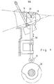
- FIG. 5 a view of the weft channel in the shed and the shielding device 11 in front of it can again be seen, similar to FIG. It carries the elongated, rotatably mounted plate 23 with which the opening 18 in the shielding plate 11 can be almost completely covered. It acts as a cleaning element and shielding plate at the same time.
- the plate 23 is pulled by the spring 24 to the eccentrically mounted stop 25, unless the plunger 27 of the magnet 26 presses upwards on the plate 23, as a result of which its right part swivels downward and widens the passage opening 18 in the shielding plate 11.
- the magnet 26 is attached to the cross member 28 of the weaving machine frame. Positions A and B correspond to those in FIG. 2.
- the plate 23 in Fig. 5 is replaced by the vertically moved plate 29, which is driven by the plunger 30 and the roller 31 by the cam 32, which sits on the main shaft of the weaving machine.
- the plates 23 and 29 from FIGS. 5 and 6 are moved upwards after the weft insertion means has passed and still during the weft insertion. They are in the down position for the rest of a weaving machine cycle.
- the shielding plates 16 and 17 mutually effect the plates 23 and 29 in their interaction with the shielding plate 11 in addition to the reduction of the passage opening 18, the cleaning of the surfaces facing one another.
Landscapes
- Engineering & Computer Science (AREA)
- Textile Engineering (AREA)
- Looms (AREA)
- Auxiliary Weaving Apparatuses, Weavers' Tools, And Shuttles (AREA)
Claims (4)
Priority Applications (3)
| Application Number | Priority Date | Filing Date | Title |
|---|---|---|---|
| EP85810042A EP0190535B1 (fr) | 1985-02-05 | 1985-02-05 | Dispositif pour protéger la zone d'insertion du fil de trame contre les duvets dans un métier à tisser |
| DE8585810042T DE3571841D1 (en) | 1985-02-05 | 1985-02-05 | Device to protect the insertion side of the weft against lint in looms |
| US06/814,190 US4682633A (en) | 1985-02-05 | 1985-12-27 | Device for screening fluff from entering a shed |
Applications Claiming Priority (1)
| Application Number | Priority Date | Filing Date | Title |
|---|---|---|---|
| EP85810042A EP0190535B1 (fr) | 1985-02-05 | 1985-02-05 | Dispositif pour protéger la zone d'insertion du fil de trame contre les duvets dans un métier à tisser |
Publications (2)
| Publication Number | Publication Date |
|---|---|
| EP0190535A1 EP0190535A1 (fr) | 1986-08-13 |
| EP0190535B1 true EP0190535B1 (fr) | 1989-07-26 |
Family
ID=8194624
Family Applications (1)
| Application Number | Title | Priority Date | Filing Date |
|---|---|---|---|
| EP85810042A Expired EP0190535B1 (fr) | 1985-02-05 | 1985-02-05 | Dispositif pour protéger la zone d'insertion du fil de trame contre les duvets dans un métier à tisser |
Country Status (3)
| Country | Link |
|---|---|
| US (1) | US4682633A (fr) |
| EP (1) | EP0190535B1 (fr) |
| DE (1) | DE3571841D1 (fr) |
Families Citing this family (3)
| Publication number | Priority date | Publication date | Assignee | Title |
|---|---|---|---|---|
| BE1000599A4 (nl) * | 1987-05-20 | 1989-02-14 | Picanol Nv | Werkwijze om te weven en weefmachine die deze werkwijze toepast. |
| CN111996690B (zh) * | 2020-08-31 | 2022-02-18 | 李亦晗 | 一种能够对摆梭机构清洁与散热的装置 |
| CN115584588B (zh) * | 2022-12-09 | 2023-04-11 | 优诺(天津)服装有限公司 | 一种环保清洁式服装生产用织造设备 |
Family Cites Families (10)
| Publication number | Priority date | Publication date | Assignee | Title |
|---|---|---|---|---|
| US1813217A (en) * | 1930-12-01 | 1931-07-07 | Draper Corp | Filling fork and grid cleaner |
| US2055631A (en) * | 1935-08-23 | 1936-09-29 | Albert G Osborne | Thread cleaning device |
| US2798825A (en) * | 1950-12-27 | 1957-07-09 | American Mono Rail Company | Method of removing lint from textile machines |
| US2954056A (en) * | 1958-10-22 | 1960-09-27 | Warner Swasey Co | Weaving machine |
| US3429746A (en) * | 1964-05-14 | 1969-02-25 | Parks Cramer Co | Method of cleaning looms |
| US3380482A (en) * | 1965-05-15 | 1968-04-30 | Nuovo Pignone Spa | Device for positively cutting the weft in a shuttleless loom having a continuous weft-supply mechanism |
| US3571840A (en) * | 1968-07-11 | 1971-03-23 | Eaton Yale & Towne | Cleaning apparatus for looms |
| CH534757A (de) * | 1971-08-25 | 1973-03-15 | Rueti Ag Maschf | Anordnung zum Wegführen von Fadenresten oder dgl. von einer Textilmaschine |
| JPS52155260A (en) * | 1976-06-17 | 1977-12-23 | Nissan Motor | Device for removing fly waste in fluiddjet loom |
| EP0137069A1 (fr) * | 1983-10-11 | 1985-04-17 | GebràDer Sulzer Aktiengesellschaft | Dispositif pour le nettoyage du côté insertion d'un métier à tisser |
-
1985
- 1985-02-05 EP EP85810042A patent/EP0190535B1/fr not_active Expired
- 1985-02-05 DE DE8585810042T patent/DE3571841D1/de not_active Expired
- 1985-12-27 US US06/814,190 patent/US4682633A/en not_active Expired - Fee Related
Also Published As
| Publication number | Publication date |
|---|---|
| US4682633A (en) | 1987-07-28 |
| DE3571841D1 (en) | 1989-08-31 |
| EP0190535A1 (fr) | 1986-08-13 |
Similar Documents
| Publication | Publication Date | Title |
|---|---|---|
| EP0778364B1 (fr) | Procédé et métier à tisser pour la manipulation d'un fil de trame | |
| DE69015479T2 (de) | Vorrichtung zum Reinigen von Webstühlen. | |
| DE2845299C2 (de) | Schützenlose Greifer-Webmaschine | |
| DE60016329T2 (de) | Spann- und Rückziehvorrichtung für vom Spulengatter zur Webmaschine laufenden Kettfaden | |
| EP0167831A1 (fr) | Métier à tisser circulaire | |
| DE3032929C2 (fr) | ||
| EP0190535B1 (fr) | Dispositif pour protéger la zone d'insertion du fil de trame contre les duvets dans un métier à tisser | |
| DE68916602T2 (de) | Vorrichtung zur Steuerung der Bewegung der Schusseintragsgreifer im Fach von schützenlosen Webmaschinen. | |
| EP3662100A1 (fr) | Métier circulaire | |
| EP0199880A1 (fr) | Dispositif d'insertion de trame pour métier à tisser, plus particulièrement un métier à tisser à navette à griffe | |
| DE4211786A1 (de) | Vorrichtung zum reinigen von wenigstens einem textilfaden | |
| EP0137069A1 (fr) | Dispositif pour le nettoyage du côté insertion d'un métier à tisser | |
| EP0582763A1 (fr) | Dispositif pour maintenir les fils de trames dans des métiers à tisser multiphase à foule linéaire | |
| DE2138487B2 (de) | Vorrichtung zum Herstellen von Effektgarn mittels einer Offenend-Sp innvorrichtung | |
| CH653060A5 (de) | Schusseintragskanal an einer duesenwebmaschine. | |
| EP0167829A1 (fr) | Dispositif casse-trame pour métiers à tisser circulaires | |
| EP0199881A1 (fr) | Dispositif d'insertion de trame pour les métiers à tisser à navette à pince | |
| CH657163A5 (de) | Rundwebmaschine. | |
| DE69518113T2 (de) | Verbessertes Führungssystem für den Greifereintragsband in eine schützenlose Webmaschine | |
| CH619993A5 (en) | Weaving machine | |
| DD148967A1 (de) | Pneumatische reinigungsvorrichtung,vorzugsweise fuer jacquardwebmaschinen mit elastischen harnischrueckzugselementen | |
| DE7601606U1 (de) | Bewaechterungsvorrichtung fuer tuft- und webmaschinen sowie kettbaummaschinen | |
| CH651330A5 (en) | Pneumatic cleaning device on a Jacquard loom having elastic harness return elements | |
| DE1710424C3 (de) | Staubabsaugeinrichtung für Webstühle | |
| DE69203500T2 (de) | Vorrichtung zum Spannen des Schussfadenendes in Luftdüsenwebmaschinen. |
Legal Events
| Date | Code | Title | Description |
|---|---|---|---|
| PUAI | Public reference made under article 153(3) epc to a published international application that has entered the european phase |
Free format text: ORIGINAL CODE: 0009012 |
|
| 17P | Request for examination filed |
Effective date: 19850207 |
|
| AK | Designated contracting states |
Kind code of ref document: A1 Designated state(s): AT BE CH DE FR GB IT LI LU NL SE |
|
| RBV | Designated contracting states (corrected) |
Designated state(s): DE IT |
|
| 17Q | First examination report despatched |
Effective date: 19880425 |
|
| GRAA | (expected) grant |
Free format text: ORIGINAL CODE: 0009210 |
|
| AK | Designated contracting states |
Kind code of ref document: B1 Designated state(s): DE IT |
|
| ITF | It: translation for a ep patent filed | ||
| REF | Corresponds to: |
Ref document number: 3571841 Country of ref document: DE Date of ref document: 19890831 |
|
| PLBE | No opposition filed within time limit |
Free format text: ORIGINAL CODE: 0009261 |
|
| STAA | Information on the status of an ep patent application or granted ep patent |
Free format text: STATUS: NO OPPOSITION FILED WITHIN TIME LIMIT |
|
| 26N | No opposition filed | ||
| PG25 | Lapsed in a contracting state [announced via postgrant information from national office to epo] |
Ref country code: DE Effective date: 19901101 |