EP0190573A2 - Dispositif pour séparer des documents - Google Patents
Dispositif pour séparer des documents Download PDFInfo
- Publication number
- EP0190573A2 EP0190573A2 EP86100460A EP86100460A EP0190573A2 EP 0190573 A2 EP0190573 A2 EP 0190573A2 EP 86100460 A EP86100460 A EP 86100460A EP 86100460 A EP86100460 A EP 86100460A EP 0190573 A2 EP0190573 A2 EP 0190573A2
- Authority
- EP
- European Patent Office
- Prior art keywords
- document
- transport
- roller
- boundary wall
- recording medium
- Prior art date
- Legal status (The legal status is an assumption and is not a legal conclusion. Google has not performed a legal analysis and makes no representation as to the accuracy of the status listed.)
- Granted
Links
- 239000000969 carrier Substances 0.000 claims abstract description 8
- 238000000926 separation method Methods 0.000 claims abstract description 6
- 230000032258 transport Effects 0.000 description 46
- 230000004888 barrier function Effects 0.000 description 2
- 239000000463 material Substances 0.000 description 2
- 230000005540 biological transmission Effects 0.000 description 1
- 230000007423 decrease Effects 0.000 description 1
- 230000002349 favourable effect Effects 0.000 description 1
- 238000000034 method Methods 0.000 description 1
Images
Classifications
-
- B—PERFORMING OPERATIONS; TRANSPORTING
- B65—CONVEYING; PACKING; STORING; HANDLING THIN OR FILAMENTARY MATERIAL
- B65H—HANDLING THIN OR FILAMENTARY MATERIAL, e.g. SHEETS, WEBS, CABLES
- B65H3/00—Separating articles from piles
- B65H3/46—Supplementary devices or measures to assist separation or prevent double feed
-
- B—PERFORMING OPERATIONS; TRANSPORTING
- B65—CONVEYING; PACKING; STORING; HANDLING THIN OR FILAMENTARY MATERIAL
- B65H—HANDLING THIN OR FILAMENTARY MATERIAL, e.g. SHEETS, WEBS, CABLES
- B65H2701/00—Handled material; Storage means
- B65H2701/10—Handled articles or webs
- B65H2701/19—Specific article or web
- B65H2701/1912—Banknotes, bills and cheques or the like
Definitions
- the invention relates to a device for separating record carriers which are removed from a storage container and fed to a transport route. Separation problems occur with the most varied types of record carriers, for example with banknotes, but in particular also with documents for document processing in the banking business.
- a separating device in which the recording media, in this case banknotes, are passed between two counter-rotating transport rollers, one conveyor roller driving in the direction of transport, while the second counter-rotating transport roller one holds back the second, possibly erroneously supplied, document due to its opposite drive movement.
- the known device is based on the principle that the friction between the first transport roller, which is provided with a corresponding friction lining, and the surface of the recording medium is greater than the friction between the recording medium, which is smooth per se.
- the invention is based on a device for separating record carriers, which are removed from a storage container and fed to a transport path, the record carriers passing between two counter-rotating transport rollers, the first of which moves the record carrier in the desired transport direction, while the second moves a second Retains record carrier due to the different friction conditions, and is characterized in that the second transport roller is pivotally mounted by a small amount such that the width of the passage slot between the two transport rollers automatically different adapts to strong types of record carriers.
- the second transport roller is mounted on a swivel lever which can be swiveled between adjustable stops.
- an easily rotatable sensor roller is provided, which cooperates with the back of the recording medium and the passage slot keeps open during the passage of the recording medium.
- the sensing roller is preferably held tangentially and adjustable in the circumferential direction on the axis of the second transport roller.
- the document storage container in addition to the normal, movable rear wall, also has a movable lower boundary wall and that a very long tension spring acts on the movable parts, which exerts an almost constant pressure regardless of the height of the document stack.
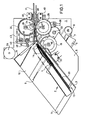
- a document storage container 2 is arranged on a holding plate 1.
- the document storage container 2 consists of a front boundary wall 3 and a displaceable, rear boundary wall 4.
- the boundary wall 4 is connected to a displaceable part, which represents the lower boundary wall 5, which is displaceably mounted on a sliding guide 6 with guide means.
- the part 4/5 is under the influence of a long tension spring 7, ' which is deflected around a roller 8 and is attached to a pin 9.
- the lower boundary wall 5 is displaced on the sliding guide 6 between two fixed boundary surfaces 10 and 11 which, in addition to the displaceable part 6, form the bottom of the document storage compartment 2.
- the part 5 transfers somewhat the level of the parts 10 and 11, so that the documents 20 of the document stack 13 only stand on the part 5.
- the rear boundary wall 4 is guided so obliquely between the parts 10 and 11 that it rests against the document stack 13 only with its right front end 12.
- a tongue of the rear boundary wall 4 is also provided with a friction lining 14 which rests on the rearmost document.
- a take-off roller 15 provided with a friction lining is mounted on an axis 16 and ensures that the foremost document 20 is always pushed out and inserted between the two boundary walls 3 and 17.
- a lateral guide part .18 is angled to the inlet opening between the guide parts 3 and 17 so that a funnel-shaped inlet opening 19 is formed.
- a limit switch 22 with a sensing arm 21 serves to completely interrupt the document transport when the document stack 13 has been processed.
- the one just described and in the F IG. 1 shown form of training the document storage container 2 has the advantage that already when introducing the documents in the document transport line precaution is taken to ensure that the documents are kept clean as the stack of documents decreases because they stand up on a movable lower boundary wall and that on the other hand the pressure on the stack of documents regardless of its size is relatively constant, so that the pre-separation by the take-off roller 15 already ensures that not too many documents are transported at the same time.
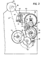
- the separating station 24 now comprises the two transport rollers 25 and 26, which are mounted on the axes 27 and 28.
- the transport roller 25 is the first transport role shown in FIG. 1 runs clockwise and which transports the document in the transport direction.
- the transport roller 26, on the other hand, is the second transport roller that is driven against the transport direction and thus has the task of pushing back the second document, which may be fed behind the foremost document 20.
- Both transport rollers 25 and 26 are provided with a corresponding friction lining.
- the second transport roller 26 and the take-off roller 15 are coated with the material Linatex. This material has proven to be particularly favorable in terms of its coefficient of friction and low wear.
- the separating device 24 and in particular its drive elements can be seen in detail from FIG. 2.
- the motor 29 drives a belt wheel 32 via a belt wheel 30 and a belt 31.
- a gear 34 is connected to the belt wheel 32 via an axis 33.
- the gear 34 engages on the one hand with the gear 35 which is mounted on the shaft 16 and drives the pull-off roller 15, on the other hand with a gear 36 which is mounted on the shaft 27 and connected to the transport roller 25.
- the gear 36 in turn drives an intermediate gear 37 which is mounted and held on a lever 38.
- the intermediate gear 37 in turn is in engagement with the gear 39, which is arranged on the shaft 28 and connected to the transport gear 26.
- the shaft 28 is attached to a pivot lever 40.
- the pivot lever 40 is rotatable about the pin 41 and has an arm 42 on which a tension spring 43 acts.
- the lever 40 can pivot about its pivot point 41 between two adjustable stops 44 and 45.
- the pivoting is so much that at most the strongest documents can pass between the two transport rollers 25 and 26.
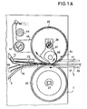
- the stop 44 is eccentric so that the basic position of the transport roller 26 can be adjusted so that the thinnest document between the two rolls 25 and 26 can happen. From FIG. 1A it can be seen that a document 20 runs between the two transport rollers 25 and 26, while the other, rear document 20 is pushed back by the transport roller 26, which runs counterclockwise, or at least is prevented from passing until the document lying in front of it is not 20 has cleared the way.
- an additional sensing roller 46 is provided, which is rotatably mounted on a holding part 47.
- the holding part 47 is fastened on the axis 28 by means of a longitudinal slot and a corresponding screw, so that it is possible to adjust the circumferential position of the sensing roller 46 and the tangential position of this roller.
- the setting is such that the sensing roller with its outermost point is offset by approximately 1 ° to 2 ° compared to the point at which the two transport rollers 25 and 26 are closest to one another, ie at which the document is gripped and transported.
- the roller 46 protrudes a very small amount beyond the circumference of the transport roller 26. So is the transport roller 26 by a stronger document 20 in FIG. 1 and 1A is pivoted counterclockwise by a small amount, then the document comes after a short further transport to the sensing roller 46 and thereby causes a slight further pivoting of the conveying roller 26.
- the F yerrolle 46 rolls while on the back side of the transported document, while the transport roller 26 is relieved. The transport of the document is facilitated in this way, the sensing roller 46 cooperating with a bulge 50 of the boundary wall 3.
Landscapes
- Engineering & Computer Science (AREA)
- Mechanical Engineering (AREA)
- Sheets, Magazines, And Separation Thereof (AREA)
- Conveying Record Carriers (AREA)
- Detergent Compositions (AREA)
- Dental Preparations (AREA)
- Photoreceptors In Electrophotography (AREA)
Priority Applications (1)
| Application Number | Priority Date | Filing Date | Title |
|---|---|---|---|
| AT86100460T ATE47120T1 (de) | 1985-01-31 | 1986-01-15 | Einrichtung zur vereinzelung von aufzeichnungstraegern. |
Applications Claiming Priority (2)
| Application Number | Priority Date | Filing Date | Title |
|---|---|---|---|
| DE3503168 | 1985-01-31 | ||
| DE19853503168 DE3503168A1 (de) | 1985-01-31 | 1985-01-31 | Einrichtung zur vereinzelung von aufzeichnungstraegern |
Publications (3)
| Publication Number | Publication Date |
|---|---|
| EP0190573A2 true EP0190573A2 (fr) | 1986-08-13 |
| EP0190573A3 EP0190573A3 (en) | 1987-04-29 |
| EP0190573B1 EP0190573B1 (fr) | 1989-10-11 |
Family
ID=6261219
Family Applications (1)
| Application Number | Title | Priority Date | Filing Date |
|---|---|---|---|
| EP86100460A Expired EP0190573B1 (fr) | 1985-01-31 | 1986-01-15 | Dispositif pour séparer des documents |
Country Status (6)
| Country | Link |
|---|---|
| US (1) | US4695048A (fr) |
| EP (1) | EP0190573B1 (fr) |
| JP (1) | JPH0435309Y2 (fr) |
| AT (1) | ATE47120T1 (fr) |
| DE (2) | DE3503168A1 (fr) |
| ES (1) | ES8701118A1 (fr) |
Cited By (2)
| Publication number | Priority date | Publication date | Assignee | Title |
|---|---|---|---|---|
| WO1989001580A1 (fr) * | 1987-08-13 | 1989-02-23 | Ncr Corporation | Mecanisme a mouvement incrementiel |
| EP0515000A1 (fr) * | 1991-05-23 | 1992-11-25 | Hadewe B.V. | Dispositif pour l'alimentation en feuilles avec une ou plusieurs couches |
Families Citing this family (10)
| Publication number | Priority date | Publication date | Assignee | Title |
|---|---|---|---|---|
| DE3508270A1 (de) * | 1985-03-08 | 1986-09-11 | Standard Elektrik Lorenz Ag, 7000 Stuttgart | Vereinzelungsvorrichtung |
| DE8703233U1 (de) * | 1987-03-03 | 1987-06-11 | Nixdorf Computer Ag, 4790 Paderborn | Ausgabevorrichtung für Blattmaterial |
| US5004219A (en) * | 1987-11-27 | 1991-04-02 | Godlewski Edward S | Up-feed conveyor system |
| JPH0297339U (fr) * | 1989-01-20 | 1990-08-02 | ||
| JP2580689Y2 (ja) * | 1992-04-06 | 1998-09-10 | 京セラ株式会社 | 自動給紙装置 |
| US5431385A (en) * | 1994-03-03 | 1995-07-11 | Pitney Bowes Inc. | Ingestion roller for mixed mail feeder |
| EP1361547A3 (fr) * | 1998-01-23 | 2005-03-30 | BEB Industrie-Elektronik AG | Capteur de position |
| DE10342568A1 (de) | 2003-09-15 | 2005-04-14 | Giesecke & Devrient Gmbh | Vorrichtung und Verfahren zum Vereinzeln von Blattgut |
| US8613444B2 (en) * | 2010-10-19 | 2013-12-24 | Xerox Corporation | Roll nip structure having adaptive pivot position |
| JP5372050B2 (ja) * | 2011-03-07 | 2013-12-18 | 京セラドキュメントソリューションズ株式会社 | 原稿搬送装置及び画像形成装置 |
Family Cites Families (11)
| Publication number | Priority date | Publication date | Assignee | Title |
|---|---|---|---|---|
| US2670954A (en) * | 1951-03-09 | 1954-03-02 | Pitney Bowes Inc | Sheet feed control device |
| US3825248A (en) * | 1972-09-07 | 1974-07-23 | L Friend | Singulator device for letter mail |
| US3902712A (en) * | 1973-05-03 | 1975-09-02 | Baeuerle Gmbh Mathias | Envelope feeder |
| DE2349143A1 (de) * | 1973-09-29 | 1975-04-17 | Siemens Ag | Vorrichtung zur entnahme jeweils eines einzelnen filmblattes von einem stapel unmittelbar lose aufeinanderliegender filmblaetter |
| SE387097B (sv) * | 1975-04-07 | 1976-08-30 | Inter Innovation Ab | Anordning for uttagning av blad |
| DE2538957A1 (de) * | 1975-09-02 | 1977-03-10 | Roto Werke Gmbh | Vorrichtung zur papiervereinzelung mit papierdicken-automatik |
| DE2650564B1 (de) * | 1976-11-04 | 1978-02-16 | Nixdorf Comp Ag | Vorrichtung zum Vereinzeln von Belegen,Karten u.dgl.,insbesondere von Geldscheinen |
| JPS5751242Y2 (fr) * | 1977-09-16 | 1982-11-09 | ||
| JPS5540505A (en) * | 1978-09-13 | 1980-03-22 | Tachikawa Spring Co | Waist bone supporting and controlling apparatus of seatback |
| JPS6039059Y2 (ja) * | 1979-06-29 | 1985-11-22 | 株式会社土屋製作所 | エアクリ−ナ用濾過エレメント |
| JPS5957841A (ja) * | 1982-09-24 | 1984-04-03 | Ricoh Co Ltd | シ−ト送り装置 |
-
1985
- 1985-01-31 DE DE19853503168 patent/DE3503168A1/de active Granted
-
1986
- 1986-01-15 EP EP86100460A patent/EP0190573B1/fr not_active Expired
- 1986-01-15 DE DE8686100460T patent/DE3666215D1/de not_active Expired
- 1986-01-15 AT AT86100460T patent/ATE47120T1/de not_active IP Right Cessation
- 1986-01-24 ES ES551236A patent/ES8701118A1/es not_active Expired
- 1986-01-30 US US06/824,153 patent/US4695048A/en not_active Expired - Fee Related
- 1986-01-31 JP JP1986011823U patent/JPH0435309Y2/ja not_active Expired
Cited By (4)
| Publication number | Priority date | Publication date | Assignee | Title |
|---|---|---|---|---|
| WO1989001580A1 (fr) * | 1987-08-13 | 1989-02-23 | Ncr Corporation | Mecanisme a mouvement incrementiel |
| US4869490A (en) * | 1987-08-13 | 1989-09-26 | Ncr Corporation | Incremental motion mechanism |
| EP0515000A1 (fr) * | 1991-05-23 | 1992-11-25 | Hadewe B.V. | Dispositif pour l'alimentation en feuilles avec une ou plusieurs couches |
| US5360206A (en) * | 1991-05-23 | 1994-11-01 | Hadewe B.V. | Apparatus for delivering flat articles comprising one or more layers |
Also Published As
| Publication number | Publication date |
|---|---|
| DE3503168A1 (de) | 1986-08-07 |
| JPH0435309Y2 (fr) | 1992-08-21 |
| EP0190573A3 (en) | 1987-04-29 |
| EP0190573B1 (fr) | 1989-10-11 |
| DE3666215D1 (en) | 1989-11-16 |
| ES551236A0 (es) | 1986-12-01 |
| US4695048A (en) | 1987-09-22 |
| DE3503168C2 (fr) | 1991-05-16 |
| JPS61130538U (fr) | 1986-08-15 |
| ATE47120T1 (de) | 1989-10-15 |
| ES8701118A1 (es) | 1986-12-01 |
Similar Documents
| Publication | Publication Date | Title |
|---|---|---|
| DE3134266C2 (de) | Vorrichtung zum Ändern der Bewegungsrichtung von in Richtung ihrer langen Kanten einlaufenden Briefen und ähnlichen rechteckigen Sendungen | |
| DE2308794C3 (de) | Vorrichtung zum Vereinzeln und Stapeln von Blättern | |
| DE2539405C2 (de) | Vorrichtung zum Vereinzeln des obersten oder untersten Blattes eines Blattstapels, insbesondere zur Verwendung in Kopiermaschinen | |
| DE2935653C2 (de) | Vorrichtung zum Vereinzeln von gestapelten Papierblättern | |
| DE2622302A1 (de) | Abzieh- und vereinzelungsvorrichtung fuer dokumente | |
| DE3508981A1 (de) | Vorrichtung zur abgabe von papierblaettern | |
| EP0535407A1 (fr) | Dispositif de marge à friction pour des feuilles en papier | |
| DE69802612T2 (de) | Reibungsunterlage für Vereinzelung von Bögen | |
| DE2516847C2 (de) | Vorrichtung zum Transportieren von zu einem Stapel vereinigten Karten oder Blättern | |
| DE2151548C3 (de) | Kartentransportvorrichtung | |
| EP0190573B1 (fr) | Dispositif pour séparer des documents | |
| DE3800638A1 (de) | Doppeldruck-drucker | |
| DE2618089A1 (de) | Vorrichtung zum einfuehren eines einzelnen blattfoermigen kopietraegers in die kopietraegertransportbahn eines kopiergeraetes | |
| DE69107412T2 (de) | Vorrichtung zum Öffnen von Briefumschlägen. | |
| DE69104700T2 (de) | Einstellbare Bogenzuführvorrichtung mit hoher Kapazität. | |
| DE2641511A1 (de) | Vorrichtung zum stapeln von flexiblen blaettern | |
| DE60104820T2 (de) | Dokumentausgabevorrichtung | |
| EP0806391B1 (fr) | Dispositif pour l'alimentation de produits imprimés vers un autre poste de travail | |
| DE69008522T2 (de) | Verfahren und vorrichtung für die zuführung von bögen. | |
| EP1832536A1 (fr) | Dispositif pour le traitement et/ou le transport d'articles postaux plats | |
| DE10101563A1 (de) | Vorrichtung zur Abgabe oder Entgegennahme von Einzelblättern | |
| DE1205113B (de) | Vorrichtung zum Vereinzeln und Abfoerdern des jeweils untersten Bogens eines Bogenstapels | |
| DE3122585C2 (de) | Vorrichtung zum Entnehmen von Filmen, insbesondere Röntgenfilmen aus einem Magazin | |
| DE2202334A1 (de) | Vorrichtung zum stapeln von blaettern | |
| DE69624325T2 (de) | Vorrichtung zum Einführen |
Legal Events
| Date | Code | Title | Description |
|---|---|---|---|
| PUAI | Public reference made under article 153(3) epc to a published international application that has entered the european phase |
Free format text: ORIGINAL CODE: 0009012 |
|
| AK | Designated contracting states |
Kind code of ref document: A2 Designated state(s): AT CH DE FR GB IT LI NL SE |
|
| PUAL | Search report despatched |
Free format text: ORIGINAL CODE: 0009013 |
|
| AK | Designated contracting states |
Kind code of ref document: A3 Designated state(s): AT CH DE FR GB IT LI NL SE |
|
| 17P | Request for examination filed |
Effective date: 19870624 |
|
| 17Q | First examination report despatched |
Effective date: 19880718 |
|
| GRAA | (expected) grant |
Free format text: ORIGINAL CODE: 0009210 |
|
| AK | Designated contracting states |
Kind code of ref document: B1 Designated state(s): AT CH DE FR GB IT LI NL SE |
|
| REF | Corresponds to: |
Ref document number: 47120 Country of ref document: AT Date of ref document: 19891015 Kind code of ref document: T |
|
| REF | Corresponds to: |
Ref document number: 3666215 Country of ref document: DE Date of ref document: 19891116 |
|
| ITF | It: translation for a ep patent filed | ||
| ET | Fr: translation filed | ||
| GBT | Gb: translation of ep patent filed (gb section 77(6)(a)/1977) | ||
| PLBE | No opposition filed within time limit |
Free format text: ORIGINAL CODE: 0009261 |
|
| STAA | Information on the status of an ep patent application or granted ep patent |
Free format text: STATUS: NO OPPOSITION FILED WITHIN TIME LIMIT |
|
| 26N | No opposition filed | ||
| PGFP | Annual fee paid to national office [announced via postgrant information from national office to epo] |
Ref country code: DE Payment date: 19920207 Year of fee payment: 7 |
|
| PG25 | Lapsed in a contracting state [announced via postgrant information from national office to epo] |
Ref country code: DE Effective date: 19940201 |
|
| PGFP | Annual fee paid to national office [announced via postgrant information from national office to epo] |
Ref country code: GB Payment date: 19950109 Year of fee payment: 10 |
|
| PGFP | Annual fee paid to national office [announced via postgrant information from national office to epo] |
Ref country code: SE Payment date: 19950124 Year of fee payment: 10 |
|
| PGFP | Annual fee paid to national office [announced via postgrant information from national office to epo] |
Ref country code: AT Payment date: 19950126 Year of fee payment: 10 |
|
| PGFP | Annual fee paid to national office [announced via postgrant information from national office to epo] |
Ref country code: FR Payment date: 19950127 Year of fee payment: 10 |
|
| EAL | Se: european patent in force in sweden |
Ref document number: 86100460.4 |
|
| ITTA | It: last paid annual fee | ||
| PGFP | Annual fee paid to national office [announced via postgrant information from national office to epo] |
Ref country code: NL Payment date: 19950131 Year of fee payment: 10 |
|
| PGFP | Annual fee paid to national office [announced via postgrant information from national office to epo] |
Ref country code: CH Payment date: 19950214 Year of fee payment: 10 |
|
| PG25 | Lapsed in a contracting state [announced via postgrant information from national office to epo] |
Ref country code: GB Effective date: 19960115 Ref country code: AT Effective date: 19960115 |
|
| PG25 | Lapsed in a contracting state [announced via postgrant information from national office to epo] |
Ref country code: SE Effective date: 19960116 |
|
| PG25 | Lapsed in a contracting state [announced via postgrant information from national office to epo] |
Ref country code: LI Effective date: 19960131 Ref country code: CH Effective date: 19960131 |
|
| PG25 | Lapsed in a contracting state [announced via postgrant information from national office to epo] |
Ref country code: NL Effective date: 19960801 |
|
| GBPC | Gb: european patent ceased through non-payment of renewal fee |
Effective date: 19960115 |
|
| REG | Reference to a national code |
Ref country code: CH Ref legal event code: PL |
|
| PG25 | Lapsed in a contracting state [announced via postgrant information from national office to epo] |
Ref country code: FR Effective date: 19960930 |
|
| NLV4 | Nl: lapsed or anulled due to non-payment of the annual fee |
Effective date: 19960801 |
|
| EUG | Se: european patent has lapsed |
Ref document number: 86100460.4 |
|
| REG | Reference to a national code |
Ref country code: FR Ref legal event code: ST |
|
| PG25 | Lapsed in a contracting state [announced via postgrant information from national office to epo] |
Ref country code: IT Free format text: LAPSE BECAUSE OF NON-PAYMENT OF DUE FEES;WARNING: LAPSES OF ITALIAN PATENTS WITH EFFECTIVE DATE BEFORE 2007 MAY HAVE OCCURRED AT ANY TIME BEFORE 2007. THE CORRECT EFFECTIVE DATE MAY BE DIFFERENT FROM THE ONE RECORDED. Effective date: 20050115 |