EP0190612A2 - Dispositif de prise d'une feuille au moyen d'une ventouse - Google Patents
Dispositif de prise d'une feuille au moyen d'une ventouse Download PDFInfo
- Publication number
- EP0190612A2 EP0190612A2 EP86100842A EP86100842A EP0190612A2 EP 0190612 A2 EP0190612 A2 EP 0190612A2 EP 86100842 A EP86100842 A EP 86100842A EP 86100842 A EP86100842 A EP 86100842A EP 0190612 A2 EP0190612 A2 EP 0190612A2
- Authority
- EP
- European Patent Office
- Prior art keywords
- film
- suction
- sheet
- edge
- suction line
- Prior art date
- Legal status (The legal status is an assumption and is not a legal conclusion. Google has not performed a legal analysis and makes no representation as to the accuracy of the status listed.)
- Granted
Links
Images

Classifications
-
- B—PERFORMING OPERATIONS; TRANSPORTING
- B65—CONVEYING; PACKING; STORING; HANDLING THIN OR FILAMENTARY MATERIAL
- B65H—HANDLING THIN OR FILAMENTARY MATERIAL, e.g. SHEETS, WEBS, CABLES
- B65H3/00—Separating articles from piles
- B65H3/08—Separating articles from piles using pneumatic force
- B65H3/0808—Suction grippers
- B65H3/0883—Construction of suction grippers or their holding devices
Definitions
- the invention relates to a device for removing a sheet of film from an X-ray film cassette or an X-ray sheet film magazine or the like, the sheet film to be removed being drawn by at least one sucker near an end face of the film to be lifted by means of a curved suction lip inner surface into which a suction line opens and which is essentially rotationally symmetrical, preferably frustoconical is suckable.
- a sucker for lifting flexible bend is known, which is followed by a bellows in the direction of the suction line, which has a lower bending stiffness to form a bending axis in two diametrical areas, the bending axis being transverse to the one to be lifted first
- the edge of the sheet or stack runs.
- the sheets to be lifted are tilted so that they are more easily separated from an underlying sheet split off.
- An absolutely safe separation of the top sheet from the sheet below it cannot be achieved with this, however, because a very strongly adhering sheet underneath u. U. still takes part in the tilting movement of a sheet to be lifted. A possibly adhering lower sheet is only shaken off after the sheet to be conveyed has been lifted off.
- the invention is based on the object of improving a device of the type mentioned in such a way that the lifting of the sheet film to be lifted takes place in such a way that air can flow in between it and the subsequent film and accelerate the detachment of the subsequent film or the base, so that a safe separation takes place with simple means before the sheet film to be conveyed is lifted off.
- a top sheet film to be lifted off is forced a small barrel-like curvature inside the suction lips of the suction device, the longitudinal axis of which extends perpendicularly to the film front edge and to the axis of the suction line and extends to the film front edge or stack edge.
- This barrel-like curvature thus forms a channel running perpendicular to the edge of the film, through which air can very quickly flow between the sheet film and the underlying sheet (further sheet film, reinforcing film, cassette bottom) flows in.
- This inflowing air immediately breaks the suction between the sheet to be lifted and its base, so that a safe and quick separation between them is ensured with the simplest means before lifting the sheet film to be lifted.
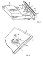
- FIG 1 denotes a storage film cassette, as z. B. is required in X-ray film cassette loading devices for the supply stack.
- a film stack with 2 the first sheet, raised by two suction cups 3 of a suction device, not shown, with 4, a stop bar arranged in front of the sheet stack 2 in the transport direction with 5 and transport rollers with 6.
- the transport rollers 6 lie in the transport direction in front of the stop bar 5.
- Two limit bars 7 are arranged on the side of the stack 2 in connection with the stop bar 5 and keep the stack 2 aligned.
- the suction cups 3 first lift the top sheet 4 perpendicular to the stack 2, so that it slides up on the stop bar 5, in order to then lift it over the stop bar 5 and feed it to the transport rollers.
- the cassette floor area is designated 8.
- Each sucker 3 has suction lips 3a, the inner surface of which is rotationally symmetrical, preferably frustoconical, and merges into the mouth 9a of a suction line 9 in its highest area as seen from the film.
- Squeegee blades 3a can along at least one outer peripheral line 3b annular grooves or dilutions have to their by comparison d ünnung rim already increased elasticity even further to increase and thereby improve application to a film 4 to be lifted off and its suction, as can be seen particularly clearly in FIG. 5b.
- suckers suck a sheet to be lifted dome-shaped and approximately symmetrical to the axis of the suction line mouth 9a, so that additional to shake off a sheet adhering to the sheet to be lifted off
- the inner surface of the suction lip 3c has, in a region near the mouth of the suction line 9a, a surface piece 10 which deviates from a truncated cone surface and has an axis running perpendicular to the front edge 4a of the film and which is recessed upwards relative to a sheet to be lifted off or forms a depression upwards . It is thereby achieved that the film surface under the nipple 3 is no longer domed, but more barrel-like, with the longitudinal axis of this barrel-like curvature being directed towards the film end edge 4a. These relatively narrow barrel-like arches extend because of their proximity to the front edge 4a and are designated by 4b in FIGS. 1 and 2.
- the surface piece 10 is formed by a cylinder inner surface piece cut with the frustoconical suction lip inner surface 3c, the surface lines 10a of which are shorter than the largest inner suction lip diameter 3d.
- the surface lines 10a run perpendicular to the film front edge 4a.
- a barrel-shaped or cylindrical curvature 4b corresponding to the shape of the cylindrical surface piece 10 is forced on the sheet film 4 which is sucked in, which continues to the edge 4a of the film, so that air flows in between the sucked-in film 4 and the underlying surface parts 2 and becomes detached, possibly adhering Documents.
- a chord 12 running through the suction line opening 9a parallel to the film front edge 4a between the most distant points of the cylindrical surface piece 10 is greater than the length of its surface lines.
- the curvature of the cylinder piece 10 receives a proportion which is particularly favorable for the formation of the barrel-shaped curvature 4b.
- FIGS. 3 to 5b Another embodiment according to FIGS. 3 to 5b has, as the surface piece 10, two wedge surface parts 10b running on both sides of the suction line opening 9a which, seen from the film front edge 4a, fall backwards.
- the axis of this surface section 10, 10b is formed as an axis of symmetry by the perpendicular to the front edge 4a running through the suction line opening 9a.
- a sucked-in sheet 4 is raised a little higher into the deeper channel between the two wedges 10b and also under the suction lips 3a near the film edge than on the opposite side.
- a barrel-like or cone-like curvature 4b the axis of which is perpendicular to the front edge 4a, is forced on the film 4.
- the suction line opening 9a is asymmetrical to the suction lips 3a, namely offset from the front edge 4a to the rear. This allows the suction device to be detached from a solid base, e.g. B. 8, facilitate when the film stack is used up.
- the innovation suction device training can be used advantageously for separating film stacks, for. B. in sheet film storage magazines. However, it can also be used just as advantageously when a single film is removed from a film cassette, because the film adhering to an intensifying film or cassette wall is also easily detached. It may be advantageous if the edge of the suction lip has a small recess 3d at a location not immediately adjacent to the film front edge 4a, which then facilitates detachment of the suction device 3 if, instead of a sheet film to be lifted off, with the cassette or already empty empty magazine sucks the amplifier film or the cassette bottom or magazine bottom 8.
- This recess 3d is so far out that it does not affect the desired suction, but that with a slight lifting of the suction device at this recess 3d air can be let in under the suction device, so that the suction device 8 can be detached from solid documents.
Landscapes
- Engineering & Computer Science (AREA)
- Mechanical Engineering (AREA)
- Sheets, Magazines, And Separation Thereof (AREA)
Applications Claiming Priority (2)
| Application Number | Priority Date | Filing Date | Title |
|---|---|---|---|
| DE3503622 | 1985-02-02 | ||
| DE19853503622 DE3503622A1 (de) | 1985-02-02 | 1985-02-02 | Vorrichtung zum entnehmen eines blattfilms mittels eines saugers |
Publications (3)
| Publication Number | Publication Date |
|---|---|
| EP0190612A2 true EP0190612A2 (fr) | 1986-08-13 |
| EP0190612A3 EP0190612A3 (en) | 1988-01-07 |
| EP0190612B1 EP0190612B1 (fr) | 1989-03-15 |
Family
ID=6261541
Family Applications (1)
| Application Number | Title | Priority Date | Filing Date |
|---|---|---|---|
| EP86100842A Expired EP0190612B1 (fr) | 1985-02-02 | 1986-01-22 | Dispositif de prise d'une feuille au moyen d'une ventouse |
Country Status (3)
| Country | Link |
|---|---|
| US (1) | US4979729A (fr) |
| EP (1) | EP0190612B1 (fr) |
| DE (2) | DE3503622A1 (fr) |
Cited By (2)
| Publication number | Priority date | Publication date | Assignee | Title |
|---|---|---|---|---|
| EP0467203A3 (en) * | 1990-07-16 | 1993-06-09 | E.I. Du Pont De Nemours And Company | Method and apparatus for moving a sheet |
| EP0819632A3 (fr) * | 1996-07-18 | 1998-09-23 | MAN Roland Druckmaschinen AG | Ventouse |
Families Citing this family (2)
| Publication number | Priority date | Publication date | Assignee | Title |
|---|---|---|---|---|
| DE102004014635B4 (de) | 2004-03-22 | 2006-01-19 | J. Schmalz Gmbh | Sauggreifer |
| US20070138733A1 (en) * | 2005-12-16 | 2007-06-21 | Chris Gray | Pick mechanism |
Family Cites Families (15)
| Publication number | Priority date | Publication date | Assignee | Title |
|---|---|---|---|---|
| DE291957C (fr) * | ||||
| US783206A (en) * | 1904-03-02 | 1905-02-21 | Charles A Juengst | Sucker device for signature or sheet gathering machines. |
| US1448690A (en) * | 1922-02-18 | 1923-03-13 | Paul C Hetzer | Vacuum cup |
| DE1676130U (de) * | 1954-02-02 | 1954-05-13 | Mabeg Maschb G M B H | Saugduese. |
| US2850279A (en) * | 1954-03-29 | 1958-09-02 | Miehle Goss Dexter Inc | Sheet separator |
| US3154306A (en) * | 1962-10-29 | 1964-10-27 | Harris Intertype Corp | Sheet-gripping sucker |
| US3230002A (en) * | 1963-04-22 | 1966-01-18 | Hyster Co | Suction cup construction and apparatus |
| US3272549A (en) * | 1965-01-13 | 1966-09-13 | Gen Electric | Materials handling device |
| US3552741A (en) * | 1968-07-26 | 1971-01-05 | Harris Intertype Corp | Sheet gripping means |
| DE1946361A1 (de) * | 1969-09-12 | 1971-04-08 | Adnumat Geraetebaugmbh & Co | Saugerkopf |
| US3724687A (en) * | 1971-03-26 | 1973-04-03 | Marguip Inc | Panel board feeding apparatus |
| DE2633831C2 (de) * | 1976-07-28 | 1978-09-07 | Vits-Maschinenbau Gmbh, 4018 Langenfeld | Sauger zum Anheben von biegsamen Gegenständen mit flacher Oberfläche, insbesondere Bogen aus Papier oder Folie |
| US4420150A (en) * | 1979-12-19 | 1983-12-13 | Ricoh Company, Ltd. | Apparatus and method for separating a single sheet from a stack and conveying it |
| US4591140A (en) * | 1983-03-12 | 1986-05-27 | Agfa-Gevaert Aktiengesellschaft | Arrangement for separating and transporting uppermost sheets of a stack of sheets or sheet-like objects |
| US4589648A (en) * | 1984-10-22 | 1986-05-20 | Westvaco Corporation | Pinch-action suction cup |
-
1985
- 1985-02-02 DE DE19853503622 patent/DE3503622A1/de active Granted
-
1986
- 1986-01-09 US US06/817,357 patent/US4979729A/en not_active Expired - Fee Related
- 1986-01-22 DE DE8686100842T patent/DE3662381D1/de not_active Expired
- 1986-01-22 EP EP86100842A patent/EP0190612B1/fr not_active Expired
Cited By (2)
| Publication number | Priority date | Publication date | Assignee | Title |
|---|---|---|---|---|
| EP0467203A3 (en) * | 1990-07-16 | 1993-06-09 | E.I. Du Pont De Nemours And Company | Method and apparatus for moving a sheet |
| EP0819632A3 (fr) * | 1996-07-18 | 1998-09-23 | MAN Roland Druckmaschinen AG | Ventouse |
Also Published As
| Publication number | Publication date |
|---|---|
| DE3503622A1 (de) | 1986-08-07 |
| EP0190612A3 (en) | 1988-01-07 |
| DE3662381D1 (en) | 1989-04-20 |
| DE3503622C2 (fr) | 1987-11-26 |
| EP0190612B1 (fr) | 1989-03-15 |
| US4979729A (en) | 1990-12-25 |
Similar Documents
| Publication | Publication Date | Title |
|---|---|---|
| EP3056294B1 (fr) | Dispositif de remplissage d'un magasin à piles de tôles métalliques | |
| EP0121803B1 (fr) | Dispositif pour séparer et transporter la feuille supérieure d'une pile de feuilles ou d'objets sous forme de feuilles | |
| CH635692A5 (de) | Einrichtung zum sammeln und stapeln von fotografischen papierbildern. | |
| DE2064452B2 (de) | Vorrichtung zum Handhaben stabförmiger Gegenstände der tabakverarbeitenden Industrie | |
| DE3211610C2 (de) | Vorrichtung zum Abnehmen eines Blattes von einem Stapel | |
| EP0280177B1 (fr) | Dispositif de déchargement de cassettes de films rayons-X | |
| EP0417503B1 (fr) | Procédé et dispositif pour le traitement ultérieur de produits imprimés empilés, de préférence pliés | |
| DE1942891A1 (de) | Verfahren und Vorrichtung zur Einbringung eines weichen Stossbogens auf mindestens eine Oberflaeche eines sich bewegenden steifen Bogens | |
| EP0190612B1 (fr) | Dispositif de prise d'une feuille au moyen d'une ventouse | |
| EP0395941A1 (fr) | Dispositif pour vider des sacs remplis de matières en vrac | |
| DE1166215B (de) | Vorrichtung zum Vereinzeln und Abziehen von Bogen aus Karton, Pappe oder aehnlichem Material | |
| DE10154235B4 (de) | Vorrichtung zum Vereinzeln scheibenförmiger, biegsamer Materialzuschnitte | |
| DE3141075A1 (de) | Zufuehreinrichtung fuer blechstreifenstapel zur zufuhr zu einem stanzautomaten | |
| DE2222066C2 (de) | Saugfuß-Trenn- und Abziehvorrichtung | |
| DE10017989B4 (de) | Verfahren und Vorrichtung zum automatischen Einzug von auf einem Sichtgerät anzuzeigenden und/oder in einem Digitalisierungsgerät abzulichtenden Dokumentenvorlagen | |
| DE3242181C2 (de) | Verfahren zum Abnehmen und Wenden der jeweils obersten Lage eines Stapels rechteckiger Kunststoffolienstücke und Vorrichtung zur Durchführung des Verfahrens | |
| DE3915284C2 (fr) | ||
| DE3404215A1 (de) | Vorrichtung zum vereinzeln und transportieren des jeweils obersten blattes eines stapels von blaettern oder blattfoermigen gegenstaenden | |
| DE3633601C2 (fr) | ||
| DE2647841C3 (de) | Vorrichtung zum Vereinzeln des obersten Blattes eines Blattstapels | |
| DE4401255C2 (de) | Vorrichtung zum Vereinzeln von Bögen eines Stapels | |
| DE3039481C1 (de) | Vorrichtung zum Trennen des obersten Bogens eines Bogenstapels | |
| DE3342510C2 (de) | Vorrichtung zum Trennen und Ausgeben von konischen Behältern | |
| DE2733391C2 (de) | Vorrichtung für ein Röntgenuntersuchungsgerät zum Abnehmen jeweils eines Filmblattes von einem Stapel | |
| DE2241910A1 (de) | Selbsttaetige papieraufgabevorrichtung |
Legal Events
| Date | Code | Title | Description |
|---|---|---|---|
| PUAI | Public reference made under article 153(3) epc to a published international application that has entered the european phase |
Free format text: ORIGINAL CODE: 0009012 |
|
| 17P | Request for examination filed |
Effective date: 19860122 |
|
| AK | Designated contracting states |
Kind code of ref document: A2 Designated state(s): DE FR GB IT |
|
| RAP1 | Party data changed (applicant data changed or rights of an application transferred) |
Owner name: AGFA-GEVAERT AG |
|
| PUAL | Search report despatched |
Free format text: ORIGINAL CODE: 0009013 |
|
| AK | Designated contracting states |
Kind code of ref document: A3 Designated state(s): DE FR GB IT |
|
| 17Q | First examination report despatched |
Effective date: 19880330 |
|
| GRAA | (expected) grant |
Free format text: ORIGINAL CODE: 0009210 |
|
| AK | Designated contracting states |
Kind code of ref document: B1 Designated state(s): DE FR GB IT |
|
| ITF | It: translation for a ep patent filed | ||
| REF | Corresponds to: |
Ref document number: 3662381 Country of ref document: DE Date of ref document: 19890420 |
|
| GBT | Gb: translation of ep patent filed (gb section 77(6)(a)/1977) | ||
| ET | Fr: translation filed | ||
| PLBE | No opposition filed within time limit |
Free format text: ORIGINAL CODE: 0009261 |
|
| STAA | Information on the status of an ep patent application or granted ep patent |
Free format text: STATUS: NO OPPOSITION FILED WITHIN TIME LIMIT |
|
| 26N | No opposition filed | ||
| ITTA | It: last paid annual fee | ||
| PGFP | Annual fee paid to national office [announced via postgrant information from national office to epo] |
Ref country code: FR Payment date: 19951228 Year of fee payment: 11 |
|
| PGFP | Annual fee paid to national office [announced via postgrant information from national office to epo] |
Ref country code: GB Payment date: 19960115 Year of fee payment: 11 |
|
| PG25 | Lapsed in a contracting state [announced via postgrant information from national office to epo] |
Ref country code: GB Effective date: 19970122 |
|
| GBPC | Gb: european patent ceased through non-payment of renewal fee |
Effective date: 19970122 |
|
| PG25 | Lapsed in a contracting state [announced via postgrant information from national office to epo] |
Ref country code: FR Effective date: 19970930 |
|
| REG | Reference to a national code |
Ref country code: FR Ref legal event code: ST |
|
| PGFP | Annual fee paid to national office [announced via postgrant information from national office to epo] |
Ref country code: DE Payment date: 20021212 Year of fee payment: 18 |
|
| PG25 | Lapsed in a contracting state [announced via postgrant information from national office to epo] |
Ref country code: DE Free format text: LAPSE BECAUSE OF NON-PAYMENT OF DUE FEES Effective date: 20040803 |
|
| PG25 | Lapsed in a contracting state [announced via postgrant information from national office to epo] |
Ref country code: IT Free format text: LAPSE BECAUSE OF NON-PAYMENT OF DUE FEES;WARNING: LAPSES OF ITALIAN PATENTS WITH EFFECTIVE DATE BEFORE 2007 MAY HAVE OCCURRED AT ANY TIME BEFORE 2007. THE CORRECT EFFECTIVE DATE MAY BE DIFFERENT FROM THE ONE RECORDED. Effective date: 20050122 |