EP0190659A2 - Chaudière - Google Patents
Chaudière Download PDFInfo
- Publication number
- EP0190659A2 EP0190659A2 EP86101187A EP86101187A EP0190659A2 EP 0190659 A2 EP0190659 A2 EP 0190659A2 EP 86101187 A EP86101187 A EP 86101187A EP 86101187 A EP86101187 A EP 86101187A EP 0190659 A2 EP0190659 A2 EP 0190659A2
- Authority
- EP
- European Patent Office
- Prior art keywords
- gas
- mixing tube
- combustion chamber
- boiler
- burner
- Prior art date
- Legal status (The legal status is an assumption and is not a legal conclusion. Google has not performed a legal analysis and makes no representation as to the accuracy of the status listed.)
- Withdrawn
Links
Images

Classifications
-
- F—MECHANICAL ENGINEERING; LIGHTING; HEATING; WEAPONS; BLASTING
- F24—HEATING; RANGES; VENTILATING
- F24H—FLUID HEATERS, e.g. WATER OR AIR HEATERS, HAVING HEAT-GENERATING MEANS, e.g. HEAT PUMPS, IN GENERAL
- F24H9/00—Details
- F24H9/18—Arrangement or mounting of grates or heating means
- F24H9/1809—Arrangement or mounting of grates or heating means for water heaters
- F24H9/1832—Arrangement or mounting of combustion heating means, e.g. grates or burners
- F24H9/1836—Arrangement or mounting of combustion heating means, e.g. grates or burners using fluid fuel
Definitions
- the invention relates to a heating boiler with a combustion chamber equipped with a gas forced draft burner with secondary heating surfaces according to the preamble of the main claim.
- Boilers of the type mentioned are generally known and with regard to the gas forced draft burners, reference is made to VDI report No. 246 1945, in particular pages 50 to 52, and also to DE-GM 80 25 383.9, the subject matter of which is, however, a burner, with which both gas and oil can be burned after a simple switchover.
- Known burners of this type in principle have a so-called mixing tube into which the gas supply tube protrudes centrally, with the gas transverse distribution over the mixing tube cross-section taking place radially between so-called baffle plates which are perforated in order to let the incoming air through and to mix it with the cross-flowing gas.
- the outflowing gas-air mixture forms a correspondingly long and concentrated flame with a high flow rate, which requires a correspondingly long combustion chamber for the boiler in question.
- the diameter of the mixing tube is in the Usually only a fraction to the radiant heat of the flame to wear (about 1/4 or 1/5) of the B race of chamber diameter and the combustion chamber door, which must be formed thermally insulated in view of the fact good bill. Due to the high pressure with which such burners are operated, they also generate considerable noise.
- the invention is therefore based on the object, starting from a heating boiler of the type mentioned, to design this in connection with the burner in such a way that the gas-air mixture formed in the form of a surface flame and with particularly improved NOx values burns directly behind the opening of the mixing tube and accordingly the burner can be operated with a low pressure blower and thus furthermore the possibility should be created to reduce the mixing tube opening size to the transverse. cut the size of the combustion chamber of the boiler equipped with such a burner, i.e. to be able to replace the otherwise insulated, heat-insulated combustion chamber door with the mixing tube.
- low pressure is to be understood here that the blower manages with approx. 50-70% less pressure than the blower for burners of the previously known type.
- Essential for this solution is the total coverage of the outflow opening of the mixing tube and the arrangement of the gas distribution elements in the middle Area of the mixing tube, so that there is a sufficiently long mixing section to the burner membrane and the gas-air mixture can flow out over the entire surface. Any of the mixture flow and the flame bundling flame tubes that normally surround the mixing tube, this is not necessary as just a surface burning Bren - is to be achieved nerflamme.
- So-called surface burners are known in the area of atmospheric gas burners, but they generally consist of three or four individual burners, for example in the form of a tube or box, the gas outflow surfaces of the individual burners also being formed from fine-hole or fine-slot surfaces.
- a planar flame in the sense provided here cannot be achieved since, depending on the gas pressure, burning individual flames are formed over the gas outlet openings of the burner surface for more or less long periods.
- the mixing tube is, as it were, a self-supporting outer part of the entire burner at the other end of the blower is directly connected in a suitable manner, it is also necessary, the mixing tube at its outer circumference with b oiler front wall connector elements to be provided.
- Such a connecting flange is advantageously arranged on the end of the mixing tube on the burner membrane side in order to be able to swing out the end of the mixing tube without taking up much space and to keep the necessary gap as small as possible.
- a direct flange connection ie without a hinge, such a gap can be kept extremely small.
- the cross-sectional size of the gas supply pipe protruding centrally into the mixing pipe is only 1 to 5% of the cross-sectional size of the mixing pipe, in contrast to previously known burners, where this ratio is about 20% ..
- the gas-blown burner for firing the boiler on the mixing tube with its connecting flange is designed as a flangeable or swivel-lockable boiler lock door forms, the burner surface forms the inflow side permanently gas-cooled and on the other hand heat-loaded surface of the boiler lock door.
- the burner surface forms the inflow side permanently gas-cooled and on the other hand heat-loaded surface of the boiler lock door.
- the fan manages with a much lower pressure, the whole thing is associated with a significantly lower noise level and a saving of additional energy for driving the fan. Since, as mentioned, the gas-air mixture continuously flows over the entire surface of the burner, the gas burns "colder" to a certain extent and, as measurements have shown, the so-called NOx formation can also be significantly reduced. Another advantage of such a boiler design is that its combustion chamber can be kept extremely short.
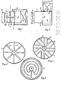
- a gas-permeable burner surface 4 which consists of a suitable metal grid or metal mesh, is arranged on or in the combustion chamber-side opening 3 of the mixing tube 1 and covers the entire opening cross section.
- the mixing tube 1 is provided on its outer circumference with boiler front wall connecting elements 5, and in the central region of the mixing tube 1 gas distribution lines 13, which are evenly distributed over the entire mixing tube cross section and are provided with gas outflow openings 12, are arranged, which are connected to the gas supply tube 14 and in the exemplary embodiments according to FIG. 1 to 4 radially from the gas supply line stick out pipe 14.
- the connecting flange 5 ' is attached to the end of the mixing tube 1 on the burner membrane side.
- an air distributor plate 10 corresponding to the mixer tube cross section is advantageously arranged in front of the gas distributor lines 13 in the mixer tube 1 and is fastened either to the mixer tube 1 or to the gas supply line 14.
- the gas supply pipe can also serve as a support for the ignition electrode 15 and an ionization electrode 16 at the same time.
- the mixing tube 1 with its connecting flange 5 1 and hinge 5 is designed as a swivel lockable boiler lock door 18, the burner surface 4 forming the gas-cooled and, on the other hand, heat-loaded surface of the boiler lock door 18 with respect to the combustion chamber 2 of the boiler in question.
- a small annular gap 20 remains free, all other heat insulation measures required on the boiler lock door 18 itself can be omitted.
- the gas-air mixture as a flat flame. front 19 burns and in contrast to the bundled flame with high flow speed and a relatively long length, there is the advantage for the boiler equipped with such a burner or such a boiler lock door that the combustion chamber 2 can be dimensioned extremely short, as can be seen from the 1, 2 can be seen. Since the secondary heating surfaces 6 can also be made very compact, this results in an extremely short boiler. Furthermore, since the flame burns as a surface flame, the front surface of the secondary heating surface 6 of the burner surface 4 can be arranged directly opposite to form a short combustion chamber length. It is also possible, however, to design the combustion chamber 2 at the rear to form an overflow chamber 7 and to arrange the secondary heating surface 6 'above the combustion chamber 2, which results in an extremely short boiler with a secondary heating surface 6' attached.
- the horizontal arrangement of the combustion chamber shown in FIGS. 1, 2 is by no means mandatory, ie the burner or the boiler lock door 18 can also, as can be seen from FIG. 6, be directed vertically downwards and also vertically upwards.
Landscapes
- Engineering & Computer Science (AREA)
- Physics & Mathematics (AREA)
- Thermal Sciences (AREA)
- Chemical & Material Sciences (AREA)
- Combustion & Propulsion (AREA)
- Mechanical Engineering (AREA)
- General Engineering & Computer Science (AREA)
- Gas Burners (AREA)
Applications Claiming Priority (2)
| Application Number | Priority Date | Filing Date | Title |
|---|---|---|---|
| DE19853503554 DE3503554A1 (de) | 1985-02-02 | 1985-02-02 | Heizungskessel |
| DE3503554 | 1985-02-02 |
Publications (2)
| Publication Number | Publication Date |
|---|---|
| EP0190659A2 true EP0190659A2 (fr) | 1986-08-13 |
| EP0190659A3 EP0190659A3 (fr) | 1987-06-03 |
Family
ID=6261487
Family Applications (1)
| Application Number | Title | Priority Date | Filing Date |
|---|---|---|---|
| EP86101187A Withdrawn EP0190659A3 (fr) | 1985-02-02 | 1986-01-30 | Chaudière |
Country Status (2)
| Country | Link |
|---|---|
| EP (1) | EP0190659A3 (fr) |
| DE (1) | DE3503554A1 (fr) |
Families Citing this family (3)
| Publication number | Priority date | Publication date | Assignee | Title |
|---|---|---|---|---|
| DE8710016U1 (de) * | 1987-07-22 | 1988-11-24 | Viessmann Werke GmbH & Co, 3559 Allendorf | Flächenbrenner |
| DE8714296U1 (de) * | 1987-10-27 | 1989-03-02 | Vießmann, Hans, Dr., 3559 Battenberg | Gasheizkessel |
| DE4108715A1 (de) * | 1991-03-18 | 1992-09-24 | Viessmann Hans | Gasbrenner fuer heizkessel |
Family Cites Families (6)
| Publication number | Priority date | Publication date | Assignee | Title |
|---|---|---|---|---|
| US3789805A (en) * | 1972-05-17 | 1974-02-05 | Massachusetts Inst Technology | Burner and heat exchanger |
| JPS5234432A (en) | 1975-09-11 | 1977-03-16 | Matsushita Electric Ind Co Ltd | Gas burner |
| NL8000460A (nl) * | 1980-01-24 | 1981-08-17 | Laurentius Cornelis Johannes L | Verwarmingsinrichting. |
| DE8025338U1 (de) * | 1980-09-22 | 1984-05-03 | Deutsche Forschungs- und Versuchsanstalt für Luft- und Raumfahrt e.V., 5000 Köln | Oel- und gasbrenner zum einbau in heizungs- und dampferzeugungskessel |
| FR2546273B1 (fr) * | 1983-05-19 | 1988-11-18 | Sdecc | Bruleur-torche a premelange d'air et de gaz |
| JP2981944B2 (ja) * | 1992-02-19 | 1999-11-22 | 松下電器産業株式会社 | パターン化した透明導電膜の形成方法 |
-
1985
- 1985-02-02 DE DE19853503554 patent/DE3503554A1/de active Granted
-
1986
- 1986-01-30 EP EP86101187A patent/EP0190659A3/fr not_active Withdrawn
Also Published As
| Publication number | Publication date |
|---|---|
| DE3503554C2 (fr) | 1987-07-16 |
| DE3503554A1 (de) | 1986-08-07 |
| EP0190659A3 (fr) | 1987-06-03 |
Similar Documents
| Publication | Publication Date | Title |
|---|---|---|
| EP0309838B1 (fr) | Brûleur à gaz | |
| WO1998043019A1 (fr) | Chaudiere de chauffage equipee d'un bruleur | |
| DE1897407U (de) | Gasbrenner. | |
| DE2363611C3 (de) | Reihenbrenner für rostartige Anordnung in einer gasbetriebenen Heizvorrichtung | |
| DE2119831C2 (de) | Gasbrenner | |
| DE2257982A1 (de) | Warmluftofen und geblaese zur verwendung im zusammenhang mit einem warmluftofen | |
| DE4406446A1 (de) | Heizeinrichtung für gasförmige Brennstoffe | |
| DE3503554C2 (fr) | ||
| DE3503553C2 (fr) | ||
| DE2156374C3 (de) | Topfvergasungsbrenner für Flüssigkeitsbrennstoff | |
| DE2656798B2 (de) | Brennkammer für einen Heizungskessel | |
| DE1213960B (de) | Schmelz- und/oder Warmhalteofen | |
| EP0706010B1 (fr) | Appareil de chauffage avec arrangement de buses | |
| DE1961932A1 (de) | Gasbrenner | |
| DE3318860C2 (de) | Brenner zum Erwärmen von Luft | |
| EP0209703B1 (fr) | Cartouche incandescente pour fours, en particulier pour chaudières ainsi que four avec une telle cartouche | |
| DE2125365C3 (de) | Strahlungsbrenner für gasförmige Brennstoffe | |
| AT389752B (de) | Feuerungsanlage | |
| DE3009764A1 (de) | Kohlebrenner | |
| DE2242037C2 (de) | Rohrförmiger Gasbrenner, insbesondere für Trockner | |
| DE1551770B2 (de) | Langgestrecktes Strahlungselement zur Oberflächenverbrennung eines Gas-Luft-Gemisches | |
| DE683981C (de) | Feuerung fuer kohlenbeheizte Kochherde u. dgl. | |
| DE1679707C3 (de) | Gasbeheizter Warmwassererhitzer | |
| DE4129552A1 (de) | Gasbrenner, insbesondere fuer fluessiggas | |
| DE1551777C (de) | Keramischer Gasbrenner fur Wind erhitzer |
Legal Events
| Date | Code | Title | Description |
|---|---|---|---|
| PUAI | Public reference made under article 153(3) epc to a published international application that has entered the european phase |
Free format text: ORIGINAL CODE: 0009012 |
|
| AK | Designated contracting states |
Kind code of ref document: A2 Designated state(s): AT BE CH FR IT LI LU NL SE |
|
| PUAL | Search report despatched |
Free format text: ORIGINAL CODE: 0009013 |
|
| AK | Designated contracting states |
Kind code of ref document: A3 Designated state(s): AT BE CH FR IT LI LU NL SE |
|
| STAA | Information on the status of an ep patent application or granted ep patent |
Free format text: STATUS: THE APPLICATION IS DEEMED TO BE WITHDRAWN |
|
| 18D | Application deemed to be withdrawn |
Effective date: 19871204 |