EP0190739A2 - Wasserentionisierungssystem - Google Patents
Wasserentionisierungssystem Download PDFInfo
- Publication number
- EP0190739A2 EP0190739A2 EP86101462A EP86101462A EP0190739A2 EP 0190739 A2 EP0190739 A2 EP 0190739A2 EP 86101462 A EP86101462 A EP 86101462A EP 86101462 A EP86101462 A EP 86101462A EP 0190739 A2 EP0190739 A2 EP 0190739A2
- Authority
- EP
- European Patent Office
- Prior art keywords
- water
- ion exchanger
- flow path
- batch
- exchanger units
- Prior art date
- Legal status (The legal status is an assumption and is not a legal conclusion. Google has not performed a legal analysis and makes no representation as to the accuracy of the status listed.)
- Granted
Links
Images

Classifications
-
- C—CHEMISTRY; METALLURGY
- C02—TREATMENT OF WATER, WASTE WATER, SEWAGE, OR SLUDGE
- C02F—TREATMENT OF WATER, WASTE WATER, SEWAGE, OR SLUDGE
- C02F9/00—Multistage treatment of water, waste water or sewage
-
- C—CHEMISTRY; METALLURGY
- C02—TREATMENT OF WATER, WASTE WATER, SEWAGE, OR SLUDGE
- C02F—TREATMENT OF WATER, WASTE WATER, SEWAGE, OR SLUDGE
- C02F1/00—Treatment of water, waste water, or sewage
- C02F1/42—Treatment of water, waste water, or sewage by ion-exchange
-
- B—PERFORMING OPERATIONS; TRANSPORTING
- B01—PHYSICAL OR CHEMICAL PROCESSES OR APPARATUS IN GENERAL
- B01J—CHEMICAL OR PHYSICAL PROCESSES, e.g. CATALYSIS OR COLLOID CHEMISTRY; THEIR RELEVANT APPARATUS
- B01J39/00—Cation exchange; Use of material as cation exchangers; Treatment of material for improving the cation exchange properties
-
- Y—GENERAL TAGGING OF NEW TECHNOLOGICAL DEVELOPMENTS; GENERAL TAGGING OF CROSS-SECTIONAL TECHNOLOGIES SPANNING OVER SEVERAL SECTIONS OF THE IPC; TECHNICAL SUBJECTS COVERED BY FORMER USPC CROSS-REFERENCE ART COLLECTIONS [XRACs] AND DIGESTS
- Y10—TECHNICAL SUBJECTS COVERED BY FORMER USPC
- Y10S—TECHNICAL SUBJECTS COVERED BY FORMER USPC CROSS-REFERENCE ART COLLECTIONS [XRACs] AND DIGESTS
- Y10S210/00—Liquid purification or separation
- Y10S210/90—Ultra pure water, e.g. conductivity water
Definitions
- This invention relates to a system for producing highly deionized water.
- deionized water A large quantity of deionized water is needed, for example, in the manufacture of various electronic devices such as semi-conductors for washing purposes.
- Prior systems for producing deionized water, especially those for producing highly deionized water are generally massive in structure and costly. Therefore, needs exist for producing a deionized water-producing system which is compact in structure and capable of producing deionized water in a reliable and stable fashion at a lower cost.
- Purified water has been conventionally produced from suitable raw water using various water-purifying techniques such as distillation, adsorption, reverse osmosis, electrodialysis, ion-exchange and combinations of these techniques.
- water-purifying techniques such as distillation, adsorption, reverse osmosis, electrodialysis, ion-exchange and combinations of these techniques.
- the use of some form of ion-exchange techniques is imperative if highly deionized water is desired.
- highly deionized water having a specific conductivity of less than 0.1 uS/cm
- water polisher containing a mixture of cationic and anionic ion-exchange materials.
- mixed bed cartridges may easily be cleansed free from mobile or unbound ions originating from activating (regenerating) agents before use, whereas cleansing of cationic and anionic ion-exchange materials placed in separate beds requires very large amounts of ultrapure water to remove mobile ions therefrom.
- mixed bed cartridges are practically incapable of regenerating their ion-exchange capacities and thus have to be disposed once their capacities have been exhausted. Since different regenerating agents are required for different ion-exchange materials, the mixture of different ion-exchange materials must be separated into its components before permitting the regeneration thereof. This separation can be done only incompletely and is not economical. It is for this reason that in prior systems mixed bed water polishers have been used in conjunction with massive pretreatment means in order to decrease loads to water polishers for extending their life.
- the present invention provides a system for producing deionized water comprising:
- the system comprises a plurality of pairs of said cationic ion exchanger unit and said anionic ion exchanger unit alternately connected in series.
- the system may further comprises a carbon filter and a membrane filter to remove contaminants other than ionic impurities.
- the system of the present invention may also be used for pretreating raw water which is ultimately treated with a mixed ion-exchanger bed, or the system itself may include a mixed ion-exchanger bed within its flow circuit.
- a water-deionizing system according to the first embodiment of the present invention is schematically illustrated.
- the system includes two pairs of a cation exchanger unit and an anion exchanger units K 1 , A 1 and K 2 , A 2 respectively. These units are connected in series so that the process water is passed through the cation exchanger unit and then the anion exchanger unit alternately or vice versa. It is preferable to use a plurality of such pairs of the ion exchanger units. This increases the efficiency of the system and also improves the quality of product water.
- a single ion exchanger unit may comprise a plurality of ion exchanger beds of the same charge.
- the system includes a carbon filter CF upstream the first pair of ion exchanger units K 1 , A 1 for adsorbing impurities such as organic contaminants, chlorine, iron rust and the like, and a membrane filter MF downstream the second pair of ion exchanger units K 2 , A 2 for removing particulate matters.
- a pump P Positioned upstream the carbon filter CF is a pump P.
- a sensor M is positioned downstream the membrane filter MF for sensing the specific conductivity of process water circulating within the system.
- a first magnetic valve MV 1 is provided between the sensor M and the pump P for selectively terminating the circulation of water in the system when product water is being discharged from the system during its second operational mode.
- Lines or conduits 10 connecting pump P, carbon filter CF, first pair of ion exchanger units K 1 and A 1 , second pair of ion exchanger units K 2 and A 2 , membrane filter MF, sensor M and magnetic valve MV 1 in a closed loop flow circuit are provided as shown.
- a raw water inlet line 16 merges with the closed loop flow circuit at a location between the first magnetic valve MV 1 and the pump P.
- a product water outlet line 18 is also provided branching from the closed loop flow circuit at a location between the sensor M and the first magnetic valve MV 1 .
- a second magnetic valve MV 2 is provided in this outlet line 18.
- a controller is provided to produce signals for selectively and alternately moving the first and second magnetic valves MV 1 and MV 2 between the open position and the closed position in response to the level of the specific conductivity sensed by the sensor M.
- the controller causes the first valve MV 1 to close and the second valve MV 2 to open when the specific conductivity is less than a first predetermined level.
- the controller causes the first valve MV 1 to open and the second valve MV 2 to close.
- a batch of raw water from suitable supply is introduced into the system via inlet line 16 with the magnetic valve MV 1 closed while the magnetic valve MV 2 open until the system is primed.
- the inlet line 16 may include a one-way valve (not shown) which is automatically closed when the liquid pressure in the system reaches at a predetermined level indicating that the system has been primed.
- Sensor M now senses a specific electric conductivity greater than the second predetermined level and the controller causes the valve MV 1 to open and the valve M 2 to close.
- the system is now ready to operate in the first mode in which the pump P is actuated to circulate the batch of water in the system through carbon filter CF, pairs of ion exchanger units K 1 , A 1 and K 2 , A 2 , and membrane filter MF repeatedly. Water is progressively deionized as it passes through pairs of ion exchanger units K 1 , A and K 2 , A 2 repeatedly. Impurities such as organic contaminants, chlorine, iron rust and the like are adsorbed by carbon filter CF and particulate matters are filter off by filter MF.
- the controller When the specific conductivity of circulating water decreases less than a predetermined first level, for example less than 0.8 ⁇ S/cm, the controller cause the valve MV l to close and the valve MV 2 to open.
- the system is now ready to operate in the second mode in which the product water is discharged from the system through outlet line 18.
- the one-way valve (not shown) associated with the raw water inlet line 16 is opened in response to the decrease in the liquid pressure in the system to charge the system with another batch of raw water.
- sensor M detects a specific conductivity greater than the second predetermined level, for example greater than 1.0 ⁇ S/cm, to switch the operation of this system to the first mode.
- the system may produce batches of deionized water intermittently by repeating the above steps.
- all ion exchanger units take the form of replaceable cartridges. This greatly decreases non-operating time associated with the in-place regeneration of spent ion exchanger units, since exhausted units may be replaced with freshly regenerated units in a short time.
- the decrease in ion exchange capacity occurs first from the pair of ion exchanger units locating at the nearest place to the raw water line 16. Because of this, it is preferable to remove this pair for regeneration and then displace the remaining pair or pairs in counter flow manner successively. Then freshly regenerated pair of ion exchanger units may be placed at the remotest location from the inlet line 16. This enables to use each pair of ion exchanger units to the fullest extent.
- FIG. 2 another embodiment of the system is illustrated.
- the same reference numerals and legends identify the same elements as in Fig. 1 and the entire system operates in the same way as in Fig. 1 embodiment except as will be discussed below.
- the system shown in Fig. 2 comprises by-pass lines 20 and 30 which by-pass the first pair of ion exchanger units K 1 , A 1 and the second pair of ion exchanger units K 2 , A 2 respectively.
- Manually operatable valves V 1 and V 4 are disposed in the main line 10 immediately upstream respective pairs of ion exchanger units K 1 , A and K 2 , A 2 and similar valves V 2 and V 3 are provided in by-pass lines 20 and 30 respectively.
- Normally valves V 2 and V 3 are closed while valves V 1 and V 4 are open.
- valve V 4 When the replacement of the first pair of units K1 , A2 is desired, one closes valve V 4 and opens valve V 3 .
- units K 2 , A3 are replaced with freshly regenerated units K 3 , A3 (not shown). Then one may open valve V 4 and close valve V 3 . Thereafter one opens valve V 2 and closes valve V 1 for replacing exhausted pair of units K 1 , A1 with units K 2 , A 2 .
- Fig. 2 may eliminate non-operating time completely. This design also allows in-place regeneration of ion exchanger units as desired without terminating the circulation of water in the system.
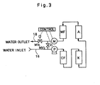
- Fig. 3 shows a system for cleansing the regenerated ion exchanger units for this purpose.
- the system shown in Fig. 3 is substantially the same as the system shown in Fig. 1 except that only a single pair of a cation exchanger unit and an anion exchanger unit is included in the system and that the circulating water passes through the anion exchanger unit upwardly. Since the upward flow may promote the free movement of ion exchanger particles within the unit housing more effectively, cleansing will be completed more rapidly than in reverse flow direction.
- an anion exchanger unit A is to be cleansed and thus water passes through the unit A in upward direction while it passes in downward direction through a cation exchanger unit K connected to the unit A upstream thereof.
- unit A has been cleansed and becomes ready for use in the system shown in Fig. 1 or F ig. 2 for replacement of exhausted ion exchanger units. It is desirable to have at least two separate such systems each exclusively for use in cleansing a particular ion exchanger material.
- the system shown in Fig. 3 enables to provide an ion exchanger unit or cartridge having a high purity and a high ion-exchange capacity. It also eliminates or minimizes needs for ultrapure water for cleansing purposes.
- a specific conductivity in the order of about 0.5 aS/cm may be attainable by the systems as shown.
- a conventional water polisher or a mixed bed ion exchanger cartridge may be interposed just upstream the membrane filter MF of the system shown in Fig. 1 or Fig. 2.
- the product water exiting outlet line 18 may be passed through a mixed bed ion exchanger cartridge.
- Such mixed bed cartridge may be prepared on site by filling a suitable housing with a mixture of different ion exchange resins regenerated and cleansed as hereinbefore discussed.
Landscapes
- Chemical & Material Sciences (AREA)
- Organic Chemistry (AREA)
- Life Sciences & Earth Sciences (AREA)
- Hydrology & Water Resources (AREA)
- Engineering & Computer Science (AREA)
- Environmental & Geological Engineering (AREA)
- Water Supply & Treatment (AREA)
- Chemical Kinetics & Catalysis (AREA)
- Separation Using Semi-Permeable Membranes (AREA)
- Treatment Of Water By Ion Exchange (AREA)
- Water Treatment By Electricity Or Magnetism (AREA)
Applications Claiming Priority (2)
| Application Number | Priority Date | Filing Date | Title |
|---|---|---|---|
| JP22285/85 | 1985-02-06 | ||
| JP60022285A JPS61181589A (ja) | 1985-02-06 | 1985-02-06 | 脱イオン純水製造装置 |
Publications (3)
| Publication Number | Publication Date |
|---|---|
| EP0190739A2 true EP0190739A2 (de) | 1986-08-13 |
| EP0190739A3 EP0190739A3 (en) | 1987-02-25 |
| EP0190739B1 EP0190739B1 (de) | 1990-08-01 |
Family
ID=12078474
Family Applications (1)
| Application Number | Title | Priority Date | Filing Date |
|---|---|---|---|
| EP86101462A Expired - Lifetime EP0190739B1 (de) | 1985-02-06 | 1986-02-05 | Wasserentionisierungssystem |
Country Status (6)
| Country | Link |
|---|---|
| US (1) | US4622133A (de) |
| EP (1) | EP0190739B1 (de) |
| JP (1) | JPS61181589A (de) |
| KR (1) | KR900000906B1 (de) |
| CA (1) | CA1268867A (de) |
| DE (1) | DE3673031D1 (de) |
Cited By (2)
| Publication number | Priority date | Publication date | Assignee | Title |
|---|---|---|---|---|
| EP0592370A1 (de) * | 1992-10-07 | 1994-04-13 | Christ AG | Verfahren zur Konditionierung von Ionenaustauschharzen |
| WO2012101419A1 (en) * | 2011-01-26 | 2012-08-02 | VWS (UK) Limited | Monitoring method |
Families Citing this family (37)
| Publication number | Priority date | Publication date | Assignee | Title |
|---|---|---|---|---|
| US4764271A (en) * | 1987-02-13 | 1988-08-16 | Acosta William A | Water treatment apparatus |
| US4904383A (en) * | 1987-05-01 | 1990-02-27 | Auerswald David C | System for demineralizing water |
| US4820421A (en) * | 1987-05-01 | 1989-04-11 | Auerswald David C | System and method for demineralizing water |
| US4784763A (en) * | 1987-07-13 | 1988-11-15 | Labconco Corporation | Water purification machine |
| US4810388A (en) * | 1987-09-08 | 1989-03-07 | Ben Trasen | Portable intravenous solutions and water for injection apparatus and method |
| US4762611A (en) * | 1987-09-16 | 1988-08-09 | Myron L Company, Inc. | Water quality indication system |
| US4847598A (en) * | 1987-11-27 | 1989-07-11 | Aqua-Tronics, Inc. | Water treatment regeneration system incorporating alternating current excitation and paired operational amplifiers with asymmetrical feedback elements |
| JPH089030B2 (ja) * | 1987-12-21 | 1996-01-31 | 三菱電機株式会社 | イオン交換樹脂による水のpH制御方法 |
| US4898667A (en) * | 1988-03-14 | 1990-02-06 | The Kendall Company | Point-of-use membrane filtration system |
| US4876014A (en) * | 1988-03-21 | 1989-10-24 | Water Systems Development Corporation | Method and apparatus for producing ultrapure water |
| US5061638A (en) * | 1989-08-18 | 1991-10-29 | Boyle Engineering Corporation | Nitrate analyzer |
| DE3939502A1 (de) * | 1989-11-30 | 1991-06-06 | Fluid Team Automationstechnik | Vorrichtung zur filtration von verunreinigten fluessigkeiten, insbesondere von wasser |
| JP2652301B2 (ja) * | 1992-05-28 | 1997-09-10 | 株式会社荏原製作所 | 洗浄水製造装置 |
| JP3170132B2 (ja) * | 1993-02-26 | 2001-05-28 | 利春 深井 | 洗剤を使用しない洗浄水と、その洗浄水の製造方法並びにその製造装置、及びその洗浄水を使用して乳化したものを水と油に分離する水と油の分離方法 |
| US5518608A (en) * | 1994-01-18 | 1996-05-21 | Chubachi; Hiroshi | Water purity determining device and system for producing ultrapure water using such devices |
| US5536411A (en) * | 1994-11-10 | 1996-07-16 | Bassai Limited | Water and energy recovery process for an ice rink |
| US5868924A (en) * | 1997-02-14 | 1999-02-09 | Barnstead/Thermolyne Corporation | Water purifier |
| DE19803967A1 (de) * | 1998-01-23 | 1999-08-05 | Intrec Ges Fuer Innovative Tec | Verfahren und Anlage zur Wasseraufbereitung, insbesondere für Wasserstrahlschneidanlagen |
| US20040020866A1 (en) * | 2002-07-22 | 2004-02-05 | Xerox Corporation | Liquid dispersion filtration and delivery apparatus and method |
| US7338595B2 (en) * | 2003-11-13 | 2008-03-04 | Culligan International Company | Flow-through tank for water treatment |
| US20050145553A1 (en) * | 2004-01-06 | 2005-07-07 | Cheng-Hwa Cheng | Chemical supply system |
| US20050279685A1 (en) * | 2004-06-21 | 2005-12-22 | Maxwell Hsu | Super oxygenated electrolised ozonated water generation system |
| US20050279690A1 (en) * | 2004-06-21 | 2005-12-22 | Maxwell Hsu | High concentration electrolised ozonated water generation system |
| US20050279688A1 (en) * | 2004-06-21 | 2005-12-22 | Maxwell Hsu | Super oxygenated electrolised ion water generation system |
| US20050279625A1 (en) * | 2004-06-21 | 2005-12-22 | Maxwell Hsu | Multifunctional oxygenated water machine |
| JP4926710B2 (ja) * | 2006-04-05 | 2012-05-09 | 三菱電機株式会社 | 液質制御方法、液質制御装置、およびこれを用いた放電加工装置 |
| US20080296215A1 (en) * | 2007-05-30 | 2008-12-04 | Simon Daniel F | Wastewater treatment and disposal system |
| CA2723899A1 (en) * | 2008-05-09 | 2009-11-12 | Wayne Slark | Method and system for treatment of water |
| US9695070B2 (en) | 2011-10-27 | 2017-07-04 | Pentair Residential Filtration, Llc | Regeneration of a capacitive deionization system |
| US8961770B2 (en) | 2011-10-27 | 2015-02-24 | Pentair Residential Filtration, Llc | Controller and method of operation of a capacitive deionization system |
| US8671985B2 (en) | 2011-10-27 | 2014-03-18 | Pentair Residential Filtration, Llc | Control valve assembly |
| US9010361B2 (en) | 2011-10-27 | 2015-04-21 | Pentair Residential Filtration, Llc | Control valve assembly |
| US9637397B2 (en) | 2011-10-27 | 2017-05-02 | Pentair Residential Filtration, Llc | Ion removal using a capacitive deionization system |
| CA2939836A1 (en) | 2014-03-13 | 2015-09-17 | Hydronovation, Inc. | Multi-port flow switching valve |
| CN104891604A (zh) * | 2015-05-19 | 2015-09-09 | 合肥天鹅制冷科技有限公司 | 去离子装置应用系统 |
| CN113874328B (zh) * | 2019-05-30 | 2023-09-12 | 奥加诺株式会社 | 超纯水制造系统及超纯水制造方法 |
| WO2021155110A1 (en) * | 2020-01-31 | 2021-08-05 | Cargill, Incorporated | Systems and methods for treatment of hard water |
Family Cites Families (10)
| Publication number | Priority date | Publication date | Assignee | Title |
|---|---|---|---|---|
| US2841550A (en) * | 1955-03-18 | 1958-07-01 | Pfandler Permutit Inc | Process of operating a demineralizing installation |
| US3276458A (en) * | 1963-01-16 | 1966-10-04 | Arthur H Iversen | Ultra pure water recirculating system |
| US3870033A (en) * | 1973-11-30 | 1975-03-11 | Aqua Media | Ultra pure water process and apparatus |
| US3985648A (en) * | 1974-06-27 | 1976-10-12 | Almag Pollution Control Corporation | Method and system for purifying liquid |
| US4280912A (en) * | 1978-05-22 | 1981-07-28 | Darco Water Systems, Inc. | Water purification unit and method |
| US4246101A (en) * | 1978-12-28 | 1981-01-20 | Pure Cycle Corporation | Water recycling system |
| US4276177A (en) * | 1979-08-13 | 1981-06-30 | Vaponics Inc. | High efficiency filtration with impurity concentration and ultrafiltration rejection flow recirculation |
| US4341636A (en) * | 1980-09-26 | 1982-07-27 | General Electric Company | Treatment of wastewater |
| CA1235235A (en) * | 1983-04-08 | 1988-04-12 | Solar Turbines Incorporated | Water treatment systems |
| US4548716A (en) * | 1984-07-25 | 1985-10-22 | Lucas Boeve | Method of producing ultrapure, pyrogen-free water |
-
1985
- 1985-02-06 JP JP60022285A patent/JPS61181589A/ja active Pending
-
1986
- 1986-01-31 CA CA000500823A patent/CA1268867A/en not_active Expired - Lifetime
- 1986-02-05 US US06/826,460 patent/US4622133A/en not_active Expired - Fee Related
- 1986-02-05 DE DE8686101462T patent/DE3673031D1/de not_active Expired - Lifetime
- 1986-02-05 EP EP86101462A patent/EP0190739B1/de not_active Expired - Lifetime
- 1986-02-06 KR KR1019860000839A patent/KR900000906B1/ko not_active Expired
Cited By (4)
| Publication number | Priority date | Publication date | Assignee | Title |
|---|---|---|---|---|
| EP0592370A1 (de) * | 1992-10-07 | 1994-04-13 | Christ AG | Verfahren zur Konditionierung von Ionenaustauschharzen |
| US5443740A (en) * | 1992-10-07 | 1995-08-22 | Christ Ag | Process for the conditioning of ion exchange resins |
| WO2012101419A1 (en) * | 2011-01-26 | 2012-08-02 | VWS (UK) Limited | Monitoring method |
| US9134264B2 (en) | 2011-01-26 | 2015-09-15 | VWS (UK) Limited | Monitoring method |
Also Published As
| Publication number | Publication date |
|---|---|
| JPS61181589A (ja) | 1986-08-14 |
| KR900000906B1 (ko) | 1990-02-19 |
| EP0190739B1 (de) | 1990-08-01 |
| EP0190739A3 (en) | 1987-02-25 |
| DE3673031D1 (de) | 1990-09-06 |
| US4622133A (en) | 1986-11-11 |
| KR860006402A (ko) | 1986-09-11 |
| CA1268867A (en) | 1990-05-08 |
Similar Documents
| Publication | Publication Date | Title |
|---|---|---|
| US4622133A (en) | Water-deionizing system | |
| US4145279A (en) | Water recycling system | |
| US4519917A (en) | Counter-current adsorption filters for the treatment of liquids and a method of operating the filter | |
| WO2006112960A2 (en) | Regeneration of adsorption media within electrodeionization purification apparatuses | |
| WO2003086629A1 (en) | Ion exchange regeneration and upw treatment system | |
| US3575294A (en) | Counterflow, moving bed type, ion exchange apparatus | |
| US3855123A (en) | Upflow-downflow sorption process | |
| US3875053A (en) | Process for carrying out ion exchange and adsorption processes using a countercurrent vessel | |
| CA1166618A (en) | Methods of ion exchange countercurrent regeneration | |
| EP0452042B1 (de) | Ionenaustauschverfahren | |
| US6228257B1 (en) | Apparatus for contacting fluids and solids | |
| US20040251191A1 (en) | Method of liquid purification using ion exchange resin being kept in a compacted state by means of elastic material | |
| JP2940651B2 (ja) | 純水製造装置 | |
| US4773979A (en) | Equipment for purifying gases and liquids | |
| US5061372A (en) | Water treatment system with preservice rinse | |
| JPS6154297A (ja) | 純水製造装置 | |
| WO2024203242A1 (ja) | 軟水化装置 | |
| GB1476032A (en) | Ion exchange units | |
| JP2742976B2 (ja) | 混床式イオン交換装置並びにこの混床式イオン交換装置を使用した純水及び超純水の製造方法 | |
| US4126548A (en) | Ion exchange process | |
| JP2576155B2 (ja) | 複層式イオン交換装置 | |
| JPH0623282A (ja) | イオン交換繊維充填筒 | |
| US6296772B1 (en) | Split ion exchange system and method of operating | |
| JP3963032B2 (ja) | イオン交換装置およびポリッシングフィルタ | |
| EP0214764A2 (de) | Methode und Vorrichtung für Ionenaustauschanwendungen |
Legal Events
| Date | Code | Title | Description |
|---|---|---|---|
| PUAI | Public reference made under article 153(3) epc to a published international application that has entered the european phase |
Free format text: ORIGINAL CODE: 0009012 |
|
| AK | Designated contracting states |
Kind code of ref document: A2 Designated state(s): DE FR GB |
|
| PUAL | Search report despatched |
Free format text: ORIGINAL CODE: 0009013 |
|
| AK | Designated contracting states |
Kind code of ref document: A3 Designated state(s): DE FR GB |
|
| 17P | Request for examination filed |
Effective date: 19870730 |
|
| 17Q | First examination report despatched |
Effective date: 19880708 |
|
| GRAA | (expected) grant |
Free format text: ORIGINAL CODE: 0009210 |
|
| AK | Designated contracting states |
Kind code of ref document: B1 Designated state(s): DE FR GB |
|
| REF | Corresponds to: |
Ref document number: 3673031 Country of ref document: DE Date of ref document: 19900906 |
|
| ET | Fr: translation filed | ||
| PLBE | No opposition filed within time limit |
Free format text: ORIGINAL CODE: 0009261 |
|
| STAA | Information on the status of an ep patent application or granted ep patent |
Free format text: STATUS: NO OPPOSITION FILED WITHIN TIME LIMIT |
|
| 26N | No opposition filed | ||
| PGFP | Annual fee paid to national office [announced via postgrant information from national office to epo] |
Ref country code: GB Payment date: 19970127 Year of fee payment: 12 |
|
| PGFP | Annual fee paid to national office [announced via postgrant information from national office to epo] |
Ref country code: FR Payment date: 19970211 Year of fee payment: 12 |
|
| PG25 | Lapsed in a contracting state [announced via postgrant information from national office to epo] |
Ref country code: GB Free format text: LAPSE BECAUSE OF NON-PAYMENT OF DUE FEES Effective date: 19980205 |
|
| PGFP | Annual fee paid to national office [announced via postgrant information from national office to epo] |
Ref country code: DE Payment date: 19980213 Year of fee payment: 13 |
|
| PG25 | Lapsed in a contracting state [announced via postgrant information from national office to epo] |
Ref country code: FR Free format text: THE PATENT HAS BEEN ANNULLED BY A DECISION OF A NATIONAL AUTHORITY Effective date: 19980228 |
|
| GBPC | Gb: european patent ceased through non-payment of renewal fee |
Effective date: 19980205 |
|
| REG | Reference to a national code |
Ref country code: FR Ref legal event code: ST |
|
| PG25 | Lapsed in a contracting state [announced via postgrant information from national office to epo] |
Ref country code: DE Free format text: LAPSE BECAUSE OF NON-PAYMENT OF DUE FEES Effective date: 19991201 |