EP0190806A2 - Méthode et dispositif pour la génération d'un signal d'appel acoustique dans des appareils d'abonnés d'installations de télécommunication - Google Patents
Méthode et dispositif pour la génération d'un signal d'appel acoustique dans des appareils d'abonnés d'installations de télécommunication Download PDFInfo
- Publication number
- EP0190806A2 EP0190806A2 EP86200165A EP86200165A EP0190806A2 EP 0190806 A2 EP0190806 A2 EP 0190806A2 EP 86200165 A EP86200165 A EP 86200165A EP 86200165 A EP86200165 A EP 86200165A EP 0190806 A2 EP0190806 A2 EP 0190806A2
- Authority
- EP
- European Patent Office
- Prior art keywords
- tone
- call
- frequency
- microprocessor
- circuit
- Prior art date
- Legal status (The legal status is an assumption and is not a legal conclusion. Google has not performed a legal analysis and makes no representation as to the accuracy of the status listed.)
- Withdrawn
Links
- 238000000034 method Methods 0.000 title claims description 15
- 230000010355 oscillation Effects 0.000 claims abstract description 10
- 230000006870 function Effects 0.000 claims abstract description 8
- 238000001514 detection method Methods 0.000 claims description 6
- 230000005540 biological transmission Effects 0.000 claims 1
- 238000011144 upstream manufacturing Methods 0.000 claims 1
- 239000003990 capacitor Substances 0.000 description 5
- 238000011156 evaluation Methods 0.000 description 3
- 239000000919 ceramic Substances 0.000 description 1
- 230000009849 deactivation Effects 0.000 description 1
- 238000007599 discharging Methods 0.000 description 1
- 239000004973 liquid crystal related substance Substances 0.000 description 1
- 239000010453 quartz Substances 0.000 description 1
- VYPSYNLAJGMNEJ-UHFFFAOYSA-N silicon dioxide Inorganic materials O=[Si]=O VYPSYNLAJGMNEJ-UHFFFAOYSA-N 0.000 description 1
- 230000001960 triggered effect Effects 0.000 description 1
Images
Classifications
-
- H—ELECTRICITY
- H04—ELECTRIC COMMUNICATION TECHNIQUE
- H04M—TELEPHONIC COMMUNICATION
- H04M19/00—Current supply arrangements for telephone systems
- H04M19/02—Current supply arrangements for telephone systems providing ringing current or supervisory tones, e.g. dialling tone or busy tone
- H04M19/04—Current supply arrangements for telephone systems providing ringing current or supervisory tones, e.g. dialling tone or busy tone the ringing-current being generated at the substations
Definitions
- the invention relates to a method for generating an acoustic call signal in subscriber terminals of telecommunications systems according to the preamble of claim 1.
- subscriber terminals are called from the switching center by the switching center superimposing an AC voltage on the DC supply voltage.
- the ringing AC voltage which e.g. in Germany has a frequency of 25 Hz, supplied to the AC alarm clock via a capacitor. If the handset is lifted from the subscriber, the loop path over the subscriber line is closed by means of the fork switch, the flow of the loop direct current is detected in the exchange and the call alternating current is switched off.
- an electronic circuit for generating the acoustic call signal is used in modern telephone sets.
- the rectified ringing alternating voltage is used to power the electronic circuit.
- a rectifier is provided for this purpose, which is followed by a filter capacitor.
- the direct voltage generated in this way is used to supply an electronic vibration generator, which in turn controls a loudspeaker for emitting sound.
- a push-button telephone which has an electronic ringing circuit (ringing IC) for the generation of the acoustic call signal.
- the ringer IC generates three frequencies: 800, 1067 and 1333 Hz, which are cyclically keyed and sent to a loudspeaker. Switching frequency and volume can be set by the participant.
- a dialing unit and a speech circuit are arranged in the push-button telephone set.
- a microcomputer for controlling the dialing unit as a function of the dialing information entered via the key set, which also controls display devices and storage devices for receiving telephone numbers or the like.
- the dialing characters are generated using the multi-frequency method (DTMF)
- an integrated circuit is also arranged in the push-button telephone set, which is controlled by the key set and generates the two frequencies (line and row frequency) each time the key is pressed, which is sent via the subscriber line to the exchange be transmitted.
- DTMF multi-frequency method
- separate ICs with associated quartz or ceramic transducers are provided in the aforementioned circuit arrangement.
- a circuit arrangement for generating an acoustic call signal in subscriber stations of telecommunications systems is known.
- a rectifier arrangement is provided in the subscriber terminal, which rectifies the supply voltage for a switching device (tone call circuit) from the alternating call current supplied via the subscriber line, generates a tone-frequency vibration generator (multivibrators) and an acoustic signal element (piezo transducer).
- the piezo converter is connected to either the charging potential or the discharging potential by means of the switching device.
- the frequencies supplied by the multivibrators control the switching device, with a switching between the other two frequencies taking place as a function of one of the frequencies.
- an electronic sound alarm which has a sensing device (tone call circuit) for distinguishing between valid and invalid call signals and in which the tone call circuit has an oscillator generator with frequency determination device (tone-frequency oscillation generator) and an output circuit controls with electro-acoustic transducer (acoustic signal element).
- the known ringer circuit has the disadvantage that the circuitry required for this is very high in the subscriber terminal.
- the invention has for its object to provide a method which requires the least possible circuitry in the subscriber terminal and at the same time the false triggering of an acoustic call signal is largely avoided by interference voltages.
- the method according to the invention is based on the knowledge that the functions of the ringing circuit can be taken over by devices already present in the subscriber terminal.
- the existing microprocessor which controls display devices, dialing devices, memory as a function of operating functions entered on the keypad, and the oscillation generator, which is used to generate multi-frequency-coded dialing characters, can also be used in touch-dial devices.
- the computing time required to distinguish between valid and invalid call signals and to control the tone-frequency oscillation generator is very short and can be readily taken over by commercially available microprocessors which are used in the multi-frequency method.
- the microprocessor can carry out both the amplitude of the incoming AC voltage and the detection of the frequency. This not only largely avoids the false triggering due to interference voltage, but also improves the selection in the event of voltage peaks.
- the amplitude is detected by means of a comparator circuit or a reset circuit.
- the circuit arrangement for performing the method is simple and requires little circuitry.
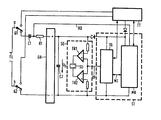
- the supply voltage U b is generated from the ringing alternating current supplied via the subscriber line TL by means of its rectification.
- the ringing alternating voltage is supplied via the wires a, b to the fork switch contacts G1, G2 and a series connection of a capacitor C1 and a resistor R1 to an alternating voltage input of the rectifier arrangement GR.
- the supply voltage U b generated by the rectifier arrangement GR is fed to a filter capacitor C2, an acoustic signal element SE and, via diodes, to the control part ST of the telephone set, consisting of a microprocessor MK and a tone-frequency vibration generator TG.
- the control part ST is supplied from the telephone circuit TT.
- the microprocessor MK is connected via a first line RD to a connection of the capacitor C1 and via a second line MT to the tone-frequency vibration generator TG.
- the tone-frequency vibration generator TG is connected to the acoustic signal element SE via a third line TF.
- the acoustic signal element SE has driver circuits TR1, TR2 and a piezo converter SU connected downstream thereof.
- the series connection of C1 and R1 is used to separate the direct current from the direct current and to limit the amplitude of the incoming alternating current.
- the microprocessor MK internally generates a reset signal when the supply voltage Ub of the rectifier arrangement GR has reached a certain level and begins to measure the frequency of the ringing signal supplied via the first line RD. If the measured frequency coincides with the predetermined frequency of the call signal (25 H z or 50 Hz), the tone-frequency oscillation generator TG is activated via the second line M T and the acoustic signal element SE is switched on. The R ufgolfrequenz is thereby also controlled by the microprocessor MK.
- the microprocessor MK therefore takes on three main tasks. Firstly, the evaluation of the amplitude of the supplied AC voltage to largely avoid false triggering of an acoustic call signal due to interference voltage, secondly, frequency detection in order to improve the selection in the event of voltage peaks, and thirdly the control when generating the ringing sequence.
- the amplitude can also be evaluated directly by comparing the ringing alternating voltage supplied via the first line RD with a level specification by means of a comparator circuit.
- the microprocessor MK can carry out the frequency evaluation in the manner of a counting discriminator.
- tone-frequency vibration generator which can deliver the required frequencies under processor control.
- This base load can advantageously be simulated by the other parts TT of the telephone set, the deactivation of this base load e.g. can be done directly by the microprocessor MK.
Landscapes
- Engineering & Computer Science (AREA)
- Signal Processing (AREA)
- Devices For Supply Of Signal Current (AREA)
- Mobile Radio Communication Systems (AREA)
Applications Claiming Priority (2)
| Application Number | Priority Date | Filing Date | Title |
|---|---|---|---|
| DE3504243 | 1985-02-08 | ||
| DE19853504243 DE3504243A1 (de) | 1985-02-08 | 1985-02-08 | Verfahren und schaltungsanordnung zur erzeugung eines akustischen rufsignals in teilnehmerendstellen von fernmeldeanlagen |
Publications (2)
| Publication Number | Publication Date |
|---|---|
| EP0190806A2 true EP0190806A2 (fr) | 1986-08-13 |
| EP0190806A3 EP0190806A3 (fr) | 1988-07-27 |
Family
ID=6261961
Family Applications (1)
| Application Number | Title | Priority Date | Filing Date |
|---|---|---|---|
| EP86200165A Withdrawn EP0190806A3 (fr) | 1985-02-08 | 1986-02-06 | Méthode et dispositif pour la génération d'un signal d'appel acoustique dans des appareils d'abonnés d'installations de télécommunication |
Country Status (4)
| Country | Link |
|---|---|
| US (1) | US4723275A (fr) |
| EP (1) | EP0190806A3 (fr) |
| JP (1) | JPS61184951A (fr) |
| DE (1) | DE3504243A1 (fr) |
Cited By (3)
| Publication number | Priority date | Publication date | Assignee | Title |
|---|---|---|---|---|
| FR2670644A1 (fr) * | 1990-12-18 | 1992-06-19 | Lewiner Jacques | Dispositif de reinitialisation des unites de controle numerique des appareils raccordes a, ou installes dans des systemes telephoniques. |
| DE4222401A1 (de) * | 1992-07-08 | 1994-03-24 | Telefunken Microelectron | Schaltungsanordnung zur Verarbeitung von Telefon-Tonrufsignalen |
| EP0756409A1 (fr) * | 1995-07-28 | 1997-01-29 | STMicroelectronics S.r.l. | Dispositif de suppression de sonnerie parasite, particulièrement pour des sonneries auxiliaires dans des systèmes de téléphone enfichable |
Families Citing this family (8)
| Publication number | Priority date | Publication date | Assignee | Title |
|---|---|---|---|---|
| US4817135A (en) * | 1987-11-24 | 1989-03-28 | U.S. News Limited Partnership | CRT mass-distribution, preprogrammed automatic dialing mechanism and related processes |
| US5233649A (en) * | 1990-08-30 | 1993-08-03 | Guerra Jr Roy H | Telephone ringing module |
| DE4140153C2 (de) * | 1991-12-05 | 2003-04-03 | Tenovis Gmbh & Co Kg | Schaltungsanordnung für einen Fernsprechapparat mit einer Tonrufschaltung |
| DE4214125C1 (de) * | 1992-04-29 | 1993-10-21 | Siemens Ag | Verfahren zur Pegel- und Frequenzüberwachung bei der Übertragung von leitungsgebundenen Signalen für signalabhängige Vorgänge, insbesondere Tonrufeingangssignale zur Auslösung eines Tonrufes in Fernsprechendgeräten |
| KR960039774A (ko) * | 1995-04-13 | 1996-11-25 | 김광호 | 자동응답 전화기의 링음성메세지 발생장치 및 그 방법 |
| JPH10308801A (ja) | 1997-05-09 | 1998-11-17 | Matsushita Electric Ind Co Ltd | 電話機 |
| US5920624A (en) * | 1997-06-16 | 1999-07-06 | Dasym Technologies Inc. | Telephone ring signal detector |
| US10718660B2 (en) | 2017-06-13 | 2020-07-21 | Robert Bosch Gmbh | Closure detection system |
Family Cites Families (8)
| Publication number | Priority date | Publication date | Assignee | Title |
|---|---|---|---|---|
| US4192007A (en) * | 1978-05-30 | 1980-03-04 | Lorain Products Corporation | Programmable ringing generator |
| GB2037128B (en) * | 1978-11-20 | 1983-04-13 | Texas Instruments Inc | Electronic telephone on a chip |
| GB2078466B (en) * | 1980-06-20 | 1984-07-04 | Plessey Co Ltd | Micro-processor controlled coin-box telephone instruments |
| US4405833A (en) * | 1981-06-17 | 1983-09-20 | Tbs International, Inc. | Telephone call progress tone and answer identification circuit |
| FR2534756A1 (fr) * | 1982-10-13 | 1984-04-20 | Telephonie Ind Commerciale | Circuit generateur de signalisation multifrequence en association avec un microprocesseur, notamment pour poste telephonique |
| US4491691A (en) * | 1983-02-28 | 1985-01-01 | At&T Bell Laboratories | Electronic tone ringer |
| US4508937A (en) * | 1983-02-28 | 1985-04-02 | At&T Information Systems Inc. | Method and circuitry for encoding telephone ringing signals |
| NL8303701A (nl) * | 1983-10-27 | 1985-05-17 | Philips Nv | Dtmf-telefoontoestel met meervoudig gebruik van de logica van de digitale toongenerator. |
-
1985
- 1985-02-08 DE DE19853504243 patent/DE3504243A1/de not_active Withdrawn
-
1986
- 1986-02-05 US US06/826,175 patent/US4723275A/en not_active Expired - Fee Related
- 1986-02-05 JP JP61022236A patent/JPS61184951A/ja active Pending
- 1986-02-06 EP EP86200165A patent/EP0190806A3/fr not_active Withdrawn
Cited By (4)
| Publication number | Priority date | Publication date | Assignee | Title |
|---|---|---|---|---|
| FR2670644A1 (fr) * | 1990-12-18 | 1992-06-19 | Lewiner Jacques | Dispositif de reinitialisation des unites de controle numerique des appareils raccordes a, ou installes dans des systemes telephoniques. |
| DE4222401A1 (de) * | 1992-07-08 | 1994-03-24 | Telefunken Microelectron | Schaltungsanordnung zur Verarbeitung von Telefon-Tonrufsignalen |
| DE4222401C2 (de) * | 1992-07-08 | 2001-09-13 | Atmel Germany Gmbh | Schaltungsanordnung zur Verarbeitung von Telefon-Tonrufsignalen |
| EP0756409A1 (fr) * | 1995-07-28 | 1997-01-29 | STMicroelectronics S.r.l. | Dispositif de suppression de sonnerie parasite, particulièrement pour des sonneries auxiliaires dans des systèmes de téléphone enfichable |
Also Published As
| Publication number | Publication date |
|---|---|
| US4723275A (en) | 1988-02-02 |
| DE3504243A1 (de) | 1986-08-14 |
| EP0190806A3 (fr) | 1988-07-27 |
| JPS61184951A (ja) | 1986-08-18 |
Similar Documents
| Publication | Publication Date | Title |
|---|---|---|
| EP0190806A2 (fr) | Méthode et dispositif pour la génération d'un signal d'appel acoustique dans des appareils d'abonnés d'installations de télécommunication | |
| DE2436745A1 (de) | Elektronischer tonwecker | |
| DE3715580C2 (fr) | ||
| DE2749458C3 (de) | Vorrichtung zum Unterdrücken unerwünschter Klingeltöne an Fernsprechgeräten | |
| EP0788271B1 (fr) | Agencement de circuit pour la génération d'impulsions de taxation | |
| DE2903298C2 (de) | Schaltungsanordnung zur akustischen Überwachung des Wahlvorganges in Fernsprechstationen | |
| DE3783909T2 (de) | Anordnung zur berichtsmeldung in einem fernsprechsystem. | |
| DE3926149C2 (de) | Schaltungskarte für eine Telefonzentrale | |
| DE3120139C1 (de) | Schaltungsanordnung zur Anschaltung eines elektronischen Tonrufes an eine Zweiwegefernsprechstation | |
| EP0052835B1 (fr) | Montage pour dériver un signal de commande pour la lotération et le bloquage de l'émission de tonalités dans un montage d'appel par tonalités pour des installations de télécommunication | |
| DE2701217B2 (de) | Schaltungsanordnung für einen Gebührenzähler bzw. -meider an der Teilnehmerstelle | |
| DE4140153C2 (de) | Schaltungsanordnung für einen Fernsprechapparat mit einer Tonrufschaltung | |
| DE2142858B2 (de) | Schaltungsanordnung zur erzeugung eines akustischen rufsignals fuer endstellen in fernmelde-, insbesondere fernsprechanlagen mittels eines piezowandlers | |
| DE1816819C3 (de) | Zusatzschaltung für einen Fernsprechapparat zur Unterdrückung der Wählimpulse von einem nachgeschalteten Fernsprechapparat | |
| KR810000817Y1 (ko) | 전화기용 톤-링거 | |
| DE3627025C2 (fr) | ||
| DE2606280C3 (de) | Geber- und Fühleranordnung für Kennzeichen in einem Kennzeichenumsetzer kommend | |
| DE3616488A1 (de) | Teilnehmerschaltung fuer eine heimtelefonanlage | |
| DE3622711C2 (fr) | ||
| EP0051446A1 (fr) | Circuits d'interface de ligne | |
| DE3409134C2 (fr) | ||
| DE2206075A1 (de) | Schaltungsanordnung zur steuerung eines rufueberbrueckungsrelais | |
| DE2741699A1 (de) | Schaltungsanordnung zur erzeugung eines akustischen rufsignals in fernmelde-, insbesondere fernsprechanlagen | |
| JPS62217794A (ja) | 電流ル−プ形成回路 | |
| DE1103973B (de) | Schaltungsanordnung fuer Fernsprechanlagen mit an einer gemeinsamen Sprechleitung liegenden Sprechstellen |
Legal Events
| Date | Code | Title | Description |
|---|---|---|---|
| PUAI | Public reference made under article 153(3) epc to a published international application that has entered the european phase |
Free format text: ORIGINAL CODE: 0009012 |
|
| AK | Designated contracting states |
Kind code of ref document: A2 Designated state(s): DE FR GB SE |
|
| RAP1 | Party data changed (applicant data changed or rights of an application transferred) |
Owner name: N.V. PHILIPS' GLOEILAMPENFABRIEKEN Owner name: PHILIPS PATENTVERWALTUNG GMBH |
|
| PUAL | Search report despatched |
Free format text: ORIGINAL CODE: 0009013 |
|
| AK | Designated contracting states |
Kind code of ref document: A3 Designated state(s): DE FR GB SE |
|
| 17P | Request for examination filed |
Effective date: 19890117 |
|
| 17Q | First examination report despatched |
Effective date: 19910131 |
|
| STAA | Information on the status of an ep patent application or granted ep patent |
Free format text: STATUS: THE APPLICATION IS DEEMED TO BE WITHDRAWN |
|
| 18D | Application deemed to be withdrawn |
Effective date: 19910611 |
|
| RIN1 | Information on inventor provided before grant (corrected) |
Inventor name: FRERICHS, WERNER, DIPL.-ING. Inventor name: GRUCZA, HUBERT Inventor name: HIRTH, PETER, DIPL.-ING. |