EP0190809A1 - Verriegelbares Schloss - Google Patents
Verriegelbares Schloss Download PDFInfo
- Publication number
- EP0190809A1 EP0190809A1 EP86200181A EP86200181A EP0190809A1 EP 0190809 A1 EP0190809 A1 EP 0190809A1 EP 86200181 A EP86200181 A EP 86200181A EP 86200181 A EP86200181 A EP 86200181A EP 0190809 A1 EP0190809 A1 EP 0190809A1
- Authority
- EP
- European Patent Office
- Prior art keywords
- bolt
- lock
- handle
- tumbler
- slide
- Prior art date
- Legal status (The legal status is an assumption and is not a legal conclusion. Google has not performed a legal analysis and makes no representation as to the accuracy of the status listed.)
- Withdrawn
Links
- 238000006073 displacement reaction Methods 0.000 claims description 2
- 230000004075 alteration Effects 0.000 description 2
- 230000000694 effects Effects 0.000 description 1
- 238000010348 incorporation Methods 0.000 description 1
- 238000002955 isolation Methods 0.000 description 1
- 238000009877 rendering Methods 0.000 description 1
Images
Classifications
-
- E—FIXED CONSTRUCTIONS
- E05—LOCKS; KEYS; WINDOW OR DOOR FITTINGS; SAFES
- E05B—LOCKS; ACCESSORIES THEREFOR; HANDCUFFS
- E05B47/00—Operating or controlling locks or other fastening devices by electric or magnetic means
- E05B47/0001—Operating or controlling locks or other fastening devices by electric or magnetic means with electric actuators; Constructional features thereof
- E05B47/0002—Operating or controlling locks or other fastening devices by electric or magnetic means with electric actuators; Constructional features thereof with electromagnets
-
- E—FIXED CONSTRUCTIONS
- E05—LOCKS; KEYS; WINDOW OR DOOR FITTINGS; SAFES
- E05B—LOCKS; ACCESSORIES THEREFOR; HANDCUFFS
- E05B47/00—Operating or controlling locks or other fastening devices by electric or magnetic means
- E05B47/06—Controlling mechanically-operated bolts by electro-magnetically-operated detents
- E05B47/0603—Controlling mechanically-operated bolts by electro-magnetically-operated detents the detent moving rectilinearly
-
- E—FIXED CONSTRUCTIONS
- E05—LOCKS; KEYS; WINDOW OR DOOR FITTINGS; SAFES
- E05B—LOCKS; ACCESSORIES THEREFOR; HANDCUFFS
- E05B47/00—Operating or controlling locks or other fastening devices by electric or magnetic means
- E05B47/0001—Operating or controlling locks or other fastening devices by electric or magnetic means with electric actuators; Constructional features thereof
- E05B47/0002—Operating or controlling locks or other fastening devices by electric or magnetic means with electric actuators; Constructional features thereof with electromagnets
- E05B47/0006—Operating or controlling locks or other fastening devices by electric or magnetic means with electric actuators; Constructional features thereof with electromagnets having a non-movable core; with permanent magnet
-
- E—FIXED CONSTRUCTIONS
- E05—LOCKS; KEYS; WINDOW OR DOOR FITTINGS; SAFES
- E05B—LOCKS; ACCESSORIES THEREFOR; HANDCUFFS
- E05B59/00—Locks with latches separate from the lock-bolts or with a plurality of latches or lock-bolts
Definitions
- the present invention relates to a lock comprising at least one bolt slidable between an extended locking position and a retracted unlocking position by rotation of a fitting key.
- the lock is fitted with a slide operable from outside the lock, said slide being slidable at right angles to the direction of bolt movements between a position in which it does not influence the bolt movements and a position in which the displacement of the bolt from the extended locking position to the retracted unlocking position is prevented.
- Said slide may have e.g. a rest position wherein it is beyond reach of the bolt so that the bolt can be pushed from the extended locking position to the retracted unlocking position by means of a fitting key.
- the slide By lifting the locking slide, which is possible only with an extended bolt in the locking position, the slide is brought within reach of the bolt, thereby preventing the bolt from being retracted in the lock housing.
- the slide may include a slotted member adapted for up and down movement to a limited extent over pins provided in the lock housing, said member not impeding other moving parts of the lock, such as a tumbler packet.
- an electro-magnet adapted to act in two directions on a portion of the locking member projecting from the lock, that is to say, said locking member or the locking slide can move both upwardly to the operative position and downwardly to the rest position.
- a part of the locking member may extend towards the handle-operated tumbler and when the night bolt is locked, may also lock said handle-operated tumbler.
- the part of the locking member extending towards said handle-operated tumbler may project in the locking position through the strap, thereby preventing strap movements and hence handle movements.
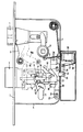
- the drawing diagrammatically shows the interior of a known type of mortise lock having the locking system according to the present invention.
- the lock comprises a day bolt 1 and a night bolt 2, both depicted in the locking position projecting from the lock plate 3.
- the lock housing 4 contains the lock mechanism comprising a tumbler 5 for a day-bolt handle, not shown.
- the tumbler 5 is connected to a return spring 7 through a strap 6.
- Acting on bolt 1 is a spring 8 loading the same to the extended locking position.
- the night bolt 2 comprises a laterally projecting locking pin 9 and a recess 10.
- a nose 13 of a cylinder 11 with key channel 12 is adapted to move night bolt 2 to and fro by engagement in the recess 10, for which purpose, however, the nose 13 should first swivel away a packet of tumblers 14 about a common pin 15, so that the locking pin 9 projecting through a recess 16 into the tumbler packet 14 is released from the locked position behind a cam 17 shown in the drawing.
- this is released from the tumblers, which are then swivelled back by tumbler springs 18 to the position shown in the drawing, wherein the locking pin 9 is again locked, but now at the other side of cam 17.
- the night bolt 2 is therefore locked also in the retracted, releasing position.
- the drawing also shows members 19, 19a enabling the day bolt to be released when the night bolt is in the released state, by once again turning the key clockwise.
- the known lock described so far includes according to the present invention, a locking member in the form of a slide 20 which, guided by slots or holes 22 engaging over pins 21 mounted in the lock housing 4, can move up and down a predetermined distance in the lock housing 4 in the plane of the night bolt 2, which in the embodiment shown is situated below the plane of the tumbler packet 14. Consequently, slide 20 can move without influencing the tumblers 14.
- Slide 20 includes a recess 23 whose form approximately corresponds with the rear of the night bolt 2 so that in the lower rest position of slide 20 shown in solid lines, the night bolt can be reciprocated by means of a fitting key without being impeded by slide 20.
- Slide 20 further includes a thickened end 24 extending in the direction of the day bolt tumbler 5, said end 24 terminating in the rest position, shown in solid lines, at some distance underneath the strap 6.
- Slide 20 moreover includes an arm 25 connected through a swivelling arm 26 to a swivelling arm 28 carrying a magnet 27.
- An electro-magnet 29 is adapted to attract and repel magnet 27.
- the slide 20 By energization of electro-magnet 29 for it to attract magnet 27, the arm 28, and hence, through swivelling arm 26 and arm 25, the slide 20, are lifted a distance defined by the length of the slotted holes 22.
- a projection 30 of the slide is present behind the night bolt 2 and in the same plane thereof, thereby preventing the night bolt from being moved clockwise from the locking position shown.
- the upper end 24 of slide 20 extends through strap 6, preventing anti-clockwise movement of strap 6, so that the handle 5 cannot be turned clockwise and the night bolt 1 cannot be retracted.
- pulses can be remotely fed to electro-magnet 29.
- the present invention is not limited to the embodiment described.
- various locking slide configurations are possible, partly depending on whether the lock in which such a member is used is fitted with one or two bolts and furthermore besides by remote control in the manner shown, the locking slide can be influenced by a separate key or otherwise from a position in the immediate proximity to the lock.
- the electro-magnet may also be mounted in the lock housing. Essential is that a simple and easily operable locking member is used that can be mounted in existing locks without alterations.
Landscapes
- Physics & Mathematics (AREA)
- Electromagnetism (AREA)
- Lock And Its Accessories (AREA)
Applications Claiming Priority (2)
| Application Number | Priority Date | Filing Date | Title |
|---|---|---|---|
| NL8500360 | 1985-02-08 | ||
| NL8500360A NL8500360A (nl) | 1985-02-08 | 1985-02-08 | Vergrendelbaar slot. |
Publications (1)
| Publication Number | Publication Date |
|---|---|
| EP0190809A1 true EP0190809A1 (de) | 1986-08-13 |
Family
ID=19845490
Family Applications (1)
| Application Number | Title | Priority Date | Filing Date |
|---|---|---|---|
| EP86200181A Withdrawn EP0190809A1 (de) | 1985-02-08 | 1986-02-07 | Verriegelbares Schloss |
Country Status (2)
| Country | Link |
|---|---|
| EP (1) | EP0190809A1 (de) |
| NL (1) | NL8500360A (de) |
Cited By (3)
| Publication number | Priority date | Publication date | Assignee | Title |
|---|---|---|---|---|
| EP0281137A3 (en) * | 1987-03-06 | 1989-07-19 | August Winkhaus Gmbh & Co Kg | Electronic door lock |
| US5014030A (en) * | 1988-11-30 | 1991-05-07 | Yale Security Products Ltd. | Electromagnetically activated mechanisms |
| CN100406672C (zh) * | 2006-05-01 | 2008-07-30 | 郑元雷 | 电控防盗门锁 |
Citations (3)
| Publication number | Priority date | Publication date | Assignee | Title |
|---|---|---|---|---|
| DE223957C (de) * | ||||
| FR354442A (fr) * | 1905-05-19 | 1905-10-05 | Andre Rondeau | Serrure électrique avertisseuse |
| US1816504A (en) * | 1929-01-07 | 1931-07-28 | Philip E Carlson | Doorlock actuating mechanism |
-
1985
- 1985-02-08 NL NL8500360A patent/NL8500360A/nl not_active Application Discontinuation
-
1986
- 1986-02-07 EP EP86200181A patent/EP0190809A1/de not_active Withdrawn
Patent Citations (3)
| Publication number | Priority date | Publication date | Assignee | Title |
|---|---|---|---|---|
| DE223957C (de) * | ||||
| FR354442A (fr) * | 1905-05-19 | 1905-10-05 | Andre Rondeau | Serrure électrique avertisseuse |
| US1816504A (en) * | 1929-01-07 | 1931-07-28 | Philip E Carlson | Doorlock actuating mechanism |
Cited By (3)
| Publication number | Priority date | Publication date | Assignee | Title |
|---|---|---|---|---|
| EP0281137A3 (en) * | 1987-03-06 | 1989-07-19 | August Winkhaus Gmbh & Co Kg | Electronic door lock |
| US5014030A (en) * | 1988-11-30 | 1991-05-07 | Yale Security Products Ltd. | Electromagnetically activated mechanisms |
| CN100406672C (zh) * | 2006-05-01 | 2008-07-30 | 郑元雷 | 电控防盗门锁 |
Also Published As
| Publication number | Publication date |
|---|---|
| NL8500360A (nl) | 1986-09-01 |
Similar Documents
| Publication | Publication Date | Title |
|---|---|---|
| US5029912A (en) | Locking device | |
| US3881331A (en) | Locking device incorporating a lock case, an escutcheon and a door handle | |
| US6048001A (en) | Push-button actuated latching mechanism | |
| US4529234A (en) | Electrical operating means for door lock mechanisms | |
| US4807455A (en) | Electromagnetically blocking and unblocking a lock for a safety deposit box, strong box or the like | |
| ATE89637T1 (de) | Elektronisches tuerschloss. | |
| GB2285280B (en) | Lock and locking assembly for a door or window | |
| MY100069A (en) | Locking mechanism with actuator | |
| US4643006A (en) | Lock having an external bolt unlocking device | |
| GB1090214A (en) | Receptacle for currency and the like | |
| US4389863A (en) | Combination locks | |
| US3760619A (en) | Cross bolt deadlock | |
| US3161035A (en) | Door chain lock | |
| ES269130U (es) | Dispositivo de cierre para puertas de frigorificos industriales, camaras y espacios similares. | |
| US2861660A (en) | Latch construction for sliding doors | |
| GB1381898A (en) | Locks for example in motor vehicle doors | |
| EP0190809A1 (de) | Verriegelbares Schloss | |
| US3087323A (en) | Mortise-type, reverse-pivoted latch mechanism | |
| US3031876A (en) | Master key controlled permutation locks | |
| US6361087B1 (en) | Locking fitting for a door, French window or the like provided with a spring-bolt elastically restored into locking position | |
| DE10143123A1 (de) | Schloss, insbesondere Schrankschloss | |
| ES8100413A1 (es) | Perfeccionamientos en las cerraduras de puerta de vehiculos a motor | |
| ES2011077A6 (es) | Cerradura con mecanismo de bloqueo y desbloqueo por medio de electroiman. | |
| GB2051217A (en) | Improvements in door bolts | |
| GB1529228A (en) | Locks |
Legal Events
| Date | Code | Title | Description |
|---|---|---|---|
| PUAI | Public reference made under article 153(3) epc to a published international application that has entered the european phase |
Free format text: ORIGINAL CODE: 0009012 |
|
| AK | Designated contracting states |
Kind code of ref document: A1 Designated state(s): BE CH DE FR GB IT LI LU NL SE |
|
| STAA | Information on the status of an ep patent application or granted ep patent |
Free format text: STATUS: THE APPLICATION IS DEEMED TO BE WITHDRAWN |
|
| 18D | Application deemed to be withdrawn |
Effective date: 19870214 |
|
| RIN1 | Information on inventor provided before grant (corrected) |
Inventor name: BRON, JOSE |