EP0190830A2 - Senseur à fibre optique unique pour mesurer la pression partielle d'oxygène - Google Patents
Senseur à fibre optique unique pour mesurer la pression partielle d'oxygène Download PDFInfo
- Publication number
- EP0190830A2 EP0190830A2 EP86300264A EP86300264A EP0190830A2 EP 0190830 A2 EP0190830 A2 EP 0190830A2 EP 86300264 A EP86300264 A EP 86300264A EP 86300264 A EP86300264 A EP 86300264A EP 0190830 A2 EP0190830 A2 EP 0190830A2
- Authority
- EP
- European Patent Office
- Prior art keywords
- oxygen
- recited
- core
- sensing
- monitoring
- Prior art date
- Legal status (The legal status is an assumption and is not a legal conclusion. Google has not performed a legal analysis and makes no representation as to the accuracy of the status listed.)
- Withdrawn
Links
Images


Classifications
-
- G—PHYSICS
- G01—MEASURING; TESTING
- G01N—INVESTIGATING OR ANALYSING MATERIALS BY DETERMINING THEIR CHEMICAL OR PHYSICAL PROPERTIES
- G01N21/00—Investigating or analysing materials by the use of optical means, i.e. using sub-millimetre waves, infrared, visible or ultraviolet light
- G01N21/62—Systems in which the material investigated is excited whereby it emits light or causes a change in wavelength of the incident light
- G01N21/63—Systems in which the material investigated is excited whereby it emits light or causes a change in wavelength of the incident light optically excited
- G01N21/64—Fluorescence; Phosphorescence
- G01N21/6428—Measuring fluorescence of fluorescent products of reactions or of fluorochrome labelled reactive substances, e.g. measuring quenching effects, using measuring "optrodes"
- G01N21/643—Measuring fluorescence of fluorescent products of reactions or of fluorochrome labelled reactive substances, e.g. measuring quenching effects, using measuring "optrodes" non-biological material
-
- C—CHEMISTRY; METALLURGY
- C09—DYES; PAINTS; POLISHES; NATURAL RESINS; ADHESIVES; COMPOSITIONS NOT OTHERWISE PROVIDED FOR; APPLICATIONS OF MATERIALS NOT OTHERWISE PROVIDED FOR
- C09K—MATERIALS FOR MISCELLANEOUS APPLICATIONS, NOT PROVIDED FOR ELSEWHERE
- C09K11/00—Luminescent materials, e.g. electroluminescent or chemiluminescent
- C09K11/06—Luminescent materials, e.g. electroluminescent or chemiluminescent containing organic luminescent materials
-
- G—PHYSICS
- G01—MEASURING; TESTING
- G01N—INVESTIGATING OR ANALYSING MATERIALS BY DETERMINING THEIR CHEMICAL OR PHYSICAL PROPERTIES
- G01N21/00—Investigating or analysing materials by the use of optical means, i.e. using sub-millimetre waves, infrared, visible or ultraviolet light
- G01N21/75—Systems in which material is subjected to a chemical reaction, the progress or the result of the reaction being investigated
- G01N21/77—Systems in which material is subjected to a chemical reaction, the progress or the result of the reaction being investigated by observing the effect on a chemical indicator
- G01N21/7703—Systems in which material is subjected to a chemical reaction, the progress or the result of the reaction being investigated by observing the effect on a chemical indicator using reagent-clad optical fibres or optical waveguides
-
- G—PHYSICS
- G01—MEASURING; TESTING
- G01N—INVESTIGATING OR ANALYSING MATERIALS BY DETERMINING THEIR CHEMICAL OR PHYSICAL PROPERTIES
- G01N21/00—Investigating or analysing materials by the use of optical means, i.e. using sub-millimetre waves, infrared, visible or ultraviolet light
- G01N21/62—Systems in which the material investigated is excited whereby it emits light or causes a change in wavelength of the incident light
- G01N21/63—Systems in which the material investigated is excited whereby it emits light or causes a change in wavelength of the incident light optically excited
- G01N21/64—Fluorescence; Phosphorescence
- G01N21/6428—Measuring fluorescence of fluorescent products of reactions or of fluorochrome labelled reactive substances, e.g. measuring quenching effects, using measuring "optrodes"
- G01N2021/6432—Quenching
-
- G—PHYSICS
- G01—MEASURING; TESTING
- G01N—INVESTIGATING OR ANALYSING MATERIALS BY DETERMINING THEIR CHEMICAL OR PHYSICAL PROPERTIES
- G01N21/00—Investigating or analysing materials by the use of optical means, i.e. using sub-millimetre waves, infrared, visible or ultraviolet light
- G01N21/75—Systems in which material is subjected to a chemical reaction, the progress or the result of the reaction being investigated
- G01N21/77—Systems in which material is subjected to a chemical reaction, the progress or the result of the reaction being investigated by observing the effect on a chemical indicator
- G01N2021/7769—Measurement method of reaction-produced change in sensor
- G01N2021/7786—Fluorescence
Definitions
- the invention relates generally to sensors for monitoring the partial pressure of oxygen in various environments and more specifically relates to fiber-optic devices for monitoring the partial pressure of oxygen in medical applications.
- Peterson Analyt. Chem., 56, 62-67 (1984).
- Peterson describes the use of a two-fiber optical cable having a sensing tip consisting of perylene dibutyrate absorbed on a powdered polystyrene support and enclosed in a gas permeable membrane. The dye is excited by light sent down one of the fibers. The resulting fluorescence is detected with the other fiber. Quenching of the fluorescence of perylene dibutyrate by oxygen is again used in this method.
- Another general type of optical device for monitoring the partial pressure of oxygen can be based on the use of ruthenium (II) complexes as luminescent sensors.
- the properties of such complexes are described in Klassen et al., “Spectroscopic Studes of Ruthenium (II) Complexes. Assignment of the Luminescence", The Journal of Chemical-Physics, Vol. 48, No. 4, (1968), Pages 1853-1858, and in Demas et al., "Energy Transfer from Luminescent Transition Metal Complexes to Oxygen", Journal of the American Chemical Society, Vol. 99, No. 11, (1977), Pages 3547-3551.
- perylene dibutyrate or pyrene dibutyric acid mounted on a solid support, or in solution, and enclosed in a membrane is unsatisfactory because of the complexity of fabrication and the poor sensitivity of the dyes.
- the luminescence of these dyes change substantially less than twofold when the partial pressure of oxygen changes from 0 to 760 mm. Hg. These changes have been measured and found to be only approximately ten percent or less.
- the ruthenium complex is much more sensitive than the other two materials, but is very slow to respond when used in unplasticized polyvinyl chloride (PVC) or silicone rubber systems described by Demas and Bacon.
- U.S. Patent Nos. 4,399,099 and 4,321,057 to Buckles describes an oxygen sensor made by coating an optical fiber core with a cladding material which interacts with oxygen thereby changing the amount of transmitted light. His method requires that both ends of the fiber be accessible so that effectively two fibers (i.e., two fiber ends) are required for a given sensor if used in a catheter application.
- the subject invention is a very fast, very sensitive, single-fiber oxygen sensor designed for remote applications in constricted environments.
- the sensor described herein is particularly useful in multisensor systems for very small channels such as in arteries and in blood vessels, or in single-lumen medical catheters.
- the invention includes an optical waveguide to receive light transmitted from a light source.
- the invention also includes an oxygen-sensing medium disposed in a portion of the core of the waveguide.
- the sensing medium fluoresces in response to light from the light source.
- the intensity of fluorescence of the sensing medium is dependent upon the partial pressure of oxygen present in the environment to be monitored.
- the portion of the core of the waveguide in which the oxygen-sensing medium is disposed is plasticized to stabilize the increased sensitivity and response rate of the sensor.
- An object of the invention is to provide a miniaturized oxygen sensor for medical applications.
- Another object of the invention is to provide an oxygen sensor which is capable of responding to very small changes in the partial pressure of oxygen on the order of 1 to 5 mm Hg.
- Another object of the invention is to provide an oxygen sensor which is easily fabricated and maintains its integrity during continued use.
- Yet another object of the invention is to provide an oxygen sensor which is not susceptible to the effects of membrane contamination when used in medical applications.
- the subject invention is a very fast, very sensitive single-fiber sensor designed for remote applications in constricted environments.
- the sensor is very easy to construct and can be used either for gas, or liquid-phase monitoring.
- the subject invention comprehends that numerous embodiments can be used with regard to both the materials used and the geometric design of the sensor.
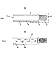
- FIG. 1 illustrates an embodiment of the subject invention.
- a sensing device 10 for sensing oxygen includes a plastic waveguide 12 having a core 14 and a cladding 16.
- the -cladding 16 surrounds a first portion of the core 14.
- the cladding is removed from a second portion of the core 18 to expose the core.
- An oxygen-sensing medium 20 is incorporated into the core using the procedure described in further detail below.
- the oxygen-sensing medium includes a fluorescent dye which can be quenched in proportion to the partial pressure of oxygen present in an environment to be monitored.
- a fluorescent dye which can be quenched in proportion to the partial pressure of oxygen present in an environment to be monitored.
- Various materials may be used for the dye as will be discussed in further detail below.
- a key feature of the subject invention is that the core of the waveguide in which the sensing medium is dispersed is plasticized to improve the performance and increase the stability of the device.
- FIG. 2 illustrates the light transmission characteristics and fluorescent characteristics of a typical sensor 24 fabricated in accordance with the subject invention.
- excitation light 26 and a fluorescent signal 28 both travel along the same optical fiber 30 so that extreme miniaturization or multiple sensors in a single small channel are possible.
- Experimental results which will be discussed in further detail below indicate that a sensor fabricated in accordance with the subject invention has at least twice the sensitivity of any of the sensors described above in the Background of the Invention where sensitivity (S) is defined by the equation: where I 0 is the intensity of the fluorescent light at 0 mm Hg, and I 760 is the intensity of fluorescent light at 760 mm Hg.
- the subject invention has a much faster response time as will be discussed below.
- Another advantage of the subject invention over the prior art is that devices fabricated in accordance with the preferred embodiment provide a much larger absolute. fluorescent signal than prior-art devices, thereby increasing the attainable precision.
- a sensor is fabricated using a 250 micron diameter plastic optical fiber having first and second ends.
- the fiber has a polyacrylic core and a fluorinated acrylic cladding in the preferred embodiment.
- the cladding is removed by dipping the first end of the fiber into an appropriate solvent which will dissolve the cladding without affecting the core.
- ethyl acetate was used as the solvent. It typically required between 30 and 120 seconds to completely remove the cladding.
- the second end of the fiber is adapted to receive light from a light source and to provide an outlet for fluoresced light to go to a signal detector.
- the second end of the fiber is provided with a plastic optical connector ferrule.
- the area surrounding the second fiber end on the ferrule surface should be blackened so as not to reflect light from the excitation light source into the signal detector.
- plasticizer used be compatible with the material used in the core of the fiber in a particular embodiment.
- a plasticizer which is compatible with the core material will leave the core uniformly translucent after the solvent evaporates, whereas a plasticizer which is not compatible with the core material will leave the- core grainy and generally opaque.
- the preferred embodiment uses an oxygen sensitive fluorescent dye of tris (4,7-diphenyl-1,10-phenanthroline) Ru(II) perchlorate.
- the oxygen-sensitive dye may be made of any salt of the tris (4,7-diphenyl-1,10-phenanthroline) Ru(II) cation.
- the anion used can be taken from the group including thiocyanate, hexafluorophosphate, tetrafluoroborate, chloride or any of the other halides.
- the oxygen-sensitive fluorescent dye is made of any salt of a transition-metal complex having as a ligand a derivative of 1,10-phenanthroline.
- the transition-metal cation should be taken from the group including ruthenium (II), osmium (II), rhodium (III), and iridium (III).
- the dye can be a derivative of pyrene or perylene.
- the sleeve may be formed of polyethylene, polypropylene, or silicone rubber microbore tubing.
- the sleeve may be applied to the sensing device 10 by sliding a tube of the particular material used over the sensing device. In other embodiments, it is possible to apply the sleeve by coating the device with the material to be used and allowing the material to cure in place about the device.
- FIG. 3 illustrates a Stern-Volmer plot showing the relative fluorescent intensity of light produced in a prior-art sensor 34 and a sensor as described herein 36 as a function of the partial pressure of oxygen.
- a Stern-Volmer plot is a graph in which the fluorescence ratio of the sensor is plotted versus the percentage or partial pressure of oxygen.
- the sensitivity of the device described herein is substantially greater than that of the prior-art sensor.
- the particular prior-art sensor that is used for comparison in FIG. 3 is a sensor of the type described above as developed by Demas and Bacon.
- the response time 38 of the device as described herein has proven to be substantially faster than the response time 40 of the prior-art device as described by Demas and Bacon. These response times were monitored for a change in the partial pressure of oxygen from 0 to 760 mn Hg.
- the present invention provides for the rapid, precise and accurate measurement of oxygen partial pressures in remote sensing applications due to the use of a very sensitive fluorescent dye incorporated into the core of an optical fiber. Furthermore, we have described a very simple method for preparing extremely small sensing devices for medical purposes in a manner easy to fabricate.
Landscapes
- Chemical & Material Sciences (AREA)
- Health & Medical Sciences (AREA)
- Physics & Mathematics (AREA)
- Immunology (AREA)
- Life Sciences & Earth Sciences (AREA)
- General Physics & Mathematics (AREA)
- Pathology (AREA)
- Analytical Chemistry (AREA)
- Biochemistry (AREA)
- General Health & Medical Sciences (AREA)
- Chemical Kinetics & Catalysis (AREA)
- Engineering & Computer Science (AREA)
- Plasma & Fusion (AREA)
- Molecular Biology (AREA)
- Optics & Photonics (AREA)
- Nuclear Medicine, Radiotherapy & Molecular Imaging (AREA)
- Materials Engineering (AREA)
- Organic Chemistry (AREA)
- Investigating Or Analysing Materials By The Use Of Chemical Reactions (AREA)
- Investigating, Analyzing Materials By Fluorescence Or Luminescence (AREA)
Applications Claiming Priority (2)
| Application Number | Priority Date | Filing Date | Title |
|---|---|---|---|
| US69828285A | 1985-02-04 | 1985-02-04 | |
| US698282 | 1985-02-04 |
Publications (2)
| Publication Number | Publication Date |
|---|---|
| EP0190830A2 true EP0190830A2 (fr) | 1986-08-13 |
| EP0190830A3 EP0190830A3 (fr) | 1988-04-27 |
Family
ID=24804618
Family Applications (1)
| Application Number | Title | Priority Date | Filing Date |
|---|---|---|---|
| EP86300264A Withdrawn EP0190830A3 (fr) | 1985-02-04 | 1986-01-16 | Senseur à fibre optique unique pour mesurer la pression partielle d'oxygène |
Country Status (2)
| Country | Link |
|---|---|
| EP (1) | EP0190830A3 (fr) |
| JP (1) | JPS61178646A (fr) |
Cited By (10)
| Publication number | Priority date | Publication date | Assignee | Title |
|---|---|---|---|---|
| AU574839B2 (en) * | 1984-09-19 | 1988-07-14 | Siemens Aktiengesellschaft | Luminescent determination of medium's parameters |
| DE3900191A1 (de) * | 1989-01-05 | 1990-07-12 | Barnikol Wolfgang | Messvorrichtung zur bestimmung des sauerstoffpartialdruckes, des sauerstoffgehaltes und des sauerstoff-flusses in biologischen systemen |
| EP0381612A1 (fr) * | 1989-02-02 | 1990-08-08 | O.C.T. Optical Chemical Technologies Limited | Sonde médicale |
| EP0352631A3 (fr) * | 1988-07-25 | 1991-07-10 | Abbott Laboratories | Système de distribution à fibres optiques dans un senseur à fibres optiques |
| WO1992008123A1 (fr) * | 1990-11-05 | 1992-05-14 | Baxter Diagnostics Inc. | Procede de mesure de reactions colorees par surveillance d'une modification de la fluorescence |
| EP0578630A1 (fr) * | 1992-07-09 | 1994-01-12 | AVL Medical Instruments AG | Membrane d'un capteur optique pour déterminer un paramètre physique ou chimique d'un échantillon |
| EP0550424A3 (fr) * | 1992-01-03 | 1994-05-04 | Hewlett Packard Co | |
| EP0585212A3 (fr) * | 1992-07-24 | 1994-11-30 | Avl Medical Instr Ag | Membrane de palpeur pour une palpeur optique. |
| US6015715A (en) * | 1995-05-27 | 2000-01-18 | Kirschner; Uwe | Method of manufacturing a sensitive single-layer system for measuring the concentration of analytes, and a system produced by this method |
| US6526213B1 (en) | 1998-05-22 | 2003-02-25 | Fiberstars Incorporated | Light pipe composition |
Families Citing this family (2)
| Publication number | Priority date | Publication date | Assignee | Title |
|---|---|---|---|---|
| JPS61201143A (ja) * | 1985-03-04 | 1986-09-05 | Agency Of Ind Science & Technol | 水素ガスセンサー |
| FR2613074B1 (fr) * | 1987-03-27 | 1990-06-08 | Commissariat Energie Atomique | Capteur chimique actif, a fibres optiques |
Family Cites Families (5)
| Publication number | Priority date | Publication date | Assignee | Title |
|---|---|---|---|---|
| DE2508637C3 (de) * | 1975-02-28 | 1979-11-22 | Max-Planck-Gesellschaft Zur Foerderung Der Wissenschaften E.V., 3400 Goettingen | Anordnung zur optischen Messung von Blutgasen |
| US4321057A (en) * | 1979-09-20 | 1982-03-23 | Buckles Richard G | Method for quantitative analysis using optical fibers |
| US4476870A (en) * | 1982-03-30 | 1984-10-16 | The United States Of America As Represented By The Department Of Health And Human Services | Fiber optic PO.sbsb.2 probe |
| AT379688B (de) * | 1982-11-22 | 1986-02-10 | List Hans | Sensorelement zur bestimmung des o2-gehaltes einer probe |
| CA1261717A (fr) * | 1982-12-23 | 1989-09-26 | John R. Bacon | Methode et appareil pour mesurer l'oxygene |
-
1986
- 1986-01-16 EP EP86300264A patent/EP0190830A3/fr not_active Withdrawn
- 1986-02-04 JP JP61021326A patent/JPS61178646A/ja active Pending
Cited By (15)
| Publication number | Priority date | Publication date | Assignee | Title |
|---|---|---|---|---|
| AU574839B2 (en) * | 1984-09-19 | 1988-07-14 | Siemens Aktiengesellschaft | Luminescent determination of medium's parameters |
| EP0352631A3 (fr) * | 1988-07-25 | 1991-07-10 | Abbott Laboratories | Système de distribution à fibres optiques dans un senseur à fibres optiques |
| DE3900191A1 (de) * | 1989-01-05 | 1990-07-12 | Barnikol Wolfgang | Messvorrichtung zur bestimmung des sauerstoffpartialdruckes, des sauerstoffgehaltes und des sauerstoff-flusses in biologischen systemen |
| DE3900191C2 (de) * | 1989-01-05 | 1998-09-03 | Barnikol Wolfgang | Meßvorrichtung zur Bestimmung des Sauerstoffpartialdruckes, des Sauerstoffgehaltes und des Sauerstoff-Flusses in biologischen Systemen |
| EP0381612A1 (fr) * | 1989-02-02 | 1990-08-08 | O.C.T. Optical Chemical Technologies Limited | Sonde médicale |
| AU652592B2 (en) * | 1990-11-05 | 1994-09-01 | Microscan, Inc. | Measurement of color reactions by monitoring a change of fluorescence |
| WO1992008123A1 (fr) * | 1990-11-05 | 1992-05-14 | Baxter Diagnostics Inc. | Procede de mesure de reactions colorees par surveillance d'une modification de la fluorescence |
| EP0550424A3 (fr) * | 1992-01-03 | 1994-05-04 | Hewlett Packard Co | |
| AT399402B (de) * | 1992-07-09 | 1995-05-26 | Avl Verbrennungskraft Messtech | Sensormembran eines optischen sensors zur bestimmung eines physikalischen oder chemischen parameters einer probe |
| EP0578630A1 (fr) * | 1992-07-09 | 1994-01-12 | AVL Medical Instruments AG | Membrane d'un capteur optique pour déterminer un paramètre physique ou chimique d'un échantillon |
| EP0585212A3 (fr) * | 1992-07-24 | 1994-11-30 | Avl Medical Instr Ag | Membrane de palpeur pour une palpeur optique. |
| AT400907B (de) * | 1992-07-24 | 1996-04-25 | Avl Verbrennungskraft Messtech | Sensormembran eines optischen sensors |
| US6139798A (en) * | 1992-07-24 | 2000-10-31 | Avl Medical Instruments Ag | Sensor membrane of an optical sensor |
| US6015715A (en) * | 1995-05-27 | 2000-01-18 | Kirschner; Uwe | Method of manufacturing a sensitive single-layer system for measuring the concentration of analytes, and a system produced by this method |
| US6526213B1 (en) | 1998-05-22 | 2003-02-25 | Fiberstars Incorporated | Light pipe composition |
Also Published As
| Publication number | Publication date |
|---|---|
| EP0190830A3 (fr) | 1988-04-27 |
| JPS61178646A (ja) | 1986-08-11 |
Similar Documents
| Publication | Publication Date | Title |
|---|---|---|
| US4752115A (en) | Optical sensor for monitoring the partial pressure of oxygen | |
| Ding et al. | Fibre optic pH sensors prepared by sol-gel immobilisation technique | |
| JP2685654B2 (ja) | 分析方法及び装置 | |
| US5714121A (en) | Optical carbon dioxide sensor, and associated methods of manufacture | |
| EP0190830A2 (fr) | Senseur à fibre optique unique pour mesurer la pression partielle d'oxygène | |
| EP0477501A2 (fr) | Appareil de contrôle en continu d'une pluralité d'analytes chimiques utilisant une fibre optique unique, et procédé de fabrication | |
| EP0457292A2 (fr) | Faisceau fibre-optique à configuration améliorée pour dispositif de mesure de gaz du sang et procédé de fabrication | |
| EP0481740A2 (fr) | Microcapteur de PH à fibre optique et procédé de fabrication | |
| US4599901A (en) | Pressure-sensitive optrode | |
| EP0490993A1 (fr) | Optrode d'ecoulement | |
| WO1997010495A1 (fr) | PROCEDE DE DETECTION A FLUORESCENCE, POUR LE pH ET LA pCO2, A DOUBLE EXCITATION ET EMISSION UNIQUE SIMULTANEES | |
| EP1864118B1 (fr) | Capteur a fibres optiques | |
| US4784811A (en) | Method of constructing improved pressure-sensitive optrode | |
| Optiz et al. | Theory and development of fluorescence-based optochemical oxygen sensors: oxygen optodes | |
| US5266271A (en) | Microsensor copolymer and method of manufacture | |
| Potyrailo et al. | Oxygen detection by fluorescence quenching of tetraphenylporphyrin immobilized in the original cladding of an optical fiber | |
| JPH01107737A (ja) | 生理学的測定装置のための光ファイバープローブコネクター | |
| EP0344313B1 (fr) | Capteur pour mesurer la concentration de gaz dissous | |
| Narayanaswamy et al. | Fibre optics for chemical sensing | |
| He et al. | Linear response function for fluorescence-based fiber-optic CO2 sensors | |
| DE10031555B4 (de) | Optischer Sensor | |
| Saari | Trends in fiber optic sensor development | |
| Varineau et al. | Determination of uranyl in aqueous solutions using a fiber-optic-based, time-resolved luminescence sensor | |
| EP0215854A1 (fr) | Senseur chimique a fibre optique | |
| Goswami et al. | Fiber optic chemical sensor for the measurement of partial pressure of oxygen |
Legal Events
| Date | Code | Title | Description |
|---|---|---|---|
| PUAI | Public reference made under article 153(3) epc to a published international application that has entered the european phase |
Free format text: ORIGINAL CODE: 0009012 |
|
| AK | Designated contracting states |
Kind code of ref document: A2 Designated state(s): BE DE FR GB IT NL |
|
| PUAL | Search report despatched |
Free format text: ORIGINAL CODE: 0009013 |
|
| AK | Designated contracting states |
Kind code of ref document: A3 Designated state(s): BE DE FR GB IT NL |
|
| STAA | Information on the status of an ep patent application or granted ep patent |
Free format text: STATUS: THE APPLICATION HAS BEEN WITHDRAWN |
|
| 18W | Application withdrawn |
Withdrawal date: 19880719 |
|
| RIN1 | Information on inventor provided before grant (corrected) |
Inventor name: LEFKOWITZ, STEVEN M. Inventor name: MURRAY, RICHARD C., JR. |