EP0190854A2 - Methode zur Herstellung von einem Träger mit senkrechter magnetischer Aufzeichnung - Google Patents
Methode zur Herstellung von einem Träger mit senkrechter magnetischer Aufzeichnung Download PDFInfo
- Publication number
- EP0190854A2 EP0190854A2 EP86300514A EP86300514A EP0190854A2 EP 0190854 A2 EP0190854 A2 EP 0190854A2 EP 86300514 A EP86300514 A EP 86300514A EP 86300514 A EP86300514 A EP 86300514A EP 0190854 A2 EP0190854 A2 EP 0190854A2
- Authority
- EP
- European Patent Office
- Prior art keywords
- magnetic film
- soft magnetic
- substrate
- film
- ion
- Prior art date
- Legal status (The legal status is an assumption and is not a legal conclusion. Google has not performed a legal analysis and makes no representation as to the accuracy of the status listed.)
- Withdrawn
Links
- 230000005291 magnetic effect Effects 0.000 title claims abstract description 245
- 238000004519 manufacturing process Methods 0.000 title claims description 11
- 239000000758 substrate Substances 0.000 claims abstract description 79
- PXHVJJICTQNCMI-UHFFFAOYSA-N nickel Substances [Ni] PXHVJJICTQNCMI-UHFFFAOYSA-N 0.000 claims abstract description 68
- 238000010884 ion-beam technique Methods 0.000 claims abstract description 42
- 238000000034 method Methods 0.000 claims abstract description 42
- 229910052742 iron Inorganic materials 0.000 claims abstract description 41
- 229910052759 nickel Inorganic materials 0.000 claims abstract description 35
- 230000015572 biosynthetic process Effects 0.000 claims abstract description 28
- 230000005855 radiation Effects 0.000 claims abstract description 27
- XEEYBQQBJWHFJM-UHFFFAOYSA-N Iron Chemical compound [Fe] XEEYBQQBJWHFJM-UHFFFAOYSA-N 0.000 claims description 82
- -1 ammonia ions Chemical class 0.000 claims description 26
- 150000002500 ions Chemical class 0.000 claims description 26
- XKRFYHLGVUSROY-UHFFFAOYSA-N Argon Chemical compound [Ar] XKRFYHLGVUSROY-UHFFFAOYSA-N 0.000 claims description 21
- 229910017052 cobalt Inorganic materials 0.000 claims description 17
- 239000010941 cobalt Substances 0.000 claims description 17
- GUTLYIVDDKVIGB-UHFFFAOYSA-N cobalt atom Chemical compound [Co] GUTLYIVDDKVIGB-UHFFFAOYSA-N 0.000 claims description 17
- 229910052751 metal Inorganic materials 0.000 claims description 17
- 239000002184 metal Substances 0.000 claims description 17
- 238000000151 deposition Methods 0.000 claims description 14
- 229910052786 argon Inorganic materials 0.000 claims description 13
- UQSXHKLRYXJYBZ-UHFFFAOYSA-N iron oxide Inorganic materials [Fe]=O UQSXHKLRYXJYBZ-UHFFFAOYSA-N 0.000 claims description 11
- VYZAMTAEIAYCRO-UHFFFAOYSA-N Chromium Chemical compound [Cr] VYZAMTAEIAYCRO-UHFFFAOYSA-N 0.000 claims description 7
- 229910052804 chromium Inorganic materials 0.000 claims description 7
- 239000011651 chromium Substances 0.000 claims description 7
- RYGMFSIKBFXOCR-UHFFFAOYSA-N Copper Chemical compound [Cu] RYGMFSIKBFXOCR-UHFFFAOYSA-N 0.000 claims description 6
- ZOKXTWBITQBERF-UHFFFAOYSA-N Molybdenum Chemical compound [Mo] ZOKXTWBITQBERF-UHFFFAOYSA-N 0.000 claims description 6
- 229910052802 copper Inorganic materials 0.000 claims description 6
- 239000010949 copper Substances 0.000 claims description 6
- 229910052750 molybdenum Inorganic materials 0.000 claims description 6
- 239000011733 molybdenum Substances 0.000 claims description 6
- QGZKDVFQNNGYKY-UHFFFAOYSA-N ammonia Natural products N QGZKDVFQNNGYKY-UHFFFAOYSA-N 0.000 claims description 5
- 229910021529 ammonia Inorganic materials 0.000 claims description 3
- 239000001257 hydrogen Substances 0.000 claims description 3
- 229910052739 hydrogen Inorganic materials 0.000 claims description 3
- WPBNNNQJVZRUHP-UHFFFAOYSA-L manganese(2+);methyl n-[[2-(methoxycarbonylcarbamothioylamino)phenyl]carbamothioyl]carbamate;n-[2-(sulfidocarbothioylamino)ethyl]carbamodithioate Chemical compound [Mn+2].[S-]C(=S)NCCNC([S-])=S.COC(=O)NC(=S)NC1=CC=CC=C1NC(=S)NC(=O)OC WPBNNNQJVZRUHP-UHFFFAOYSA-L 0.000 claims description 3
- UFHFLCQGNIYNRP-UHFFFAOYSA-N Hydrogen Chemical compound [H][H] UFHFLCQGNIYNRP-UHFFFAOYSA-N 0.000 claims description 2
- 239000001307 helium Substances 0.000 claims description 2
- 229910052734 helium Inorganic materials 0.000 claims description 2
- SWQJXJOGLNCZEY-UHFFFAOYSA-N helium atom Chemical compound [He] SWQJXJOGLNCZEY-UHFFFAOYSA-N 0.000 claims description 2
- 229910052743 krypton Inorganic materials 0.000 claims description 2
- DNNSSWSSYDEUBZ-UHFFFAOYSA-N krypton atom Chemical compound [Kr] DNNSSWSSYDEUBZ-UHFFFAOYSA-N 0.000 claims description 2
- 235000013980 iron oxide Nutrition 0.000 claims 1
- 230000008021 deposition Effects 0.000 abstract description 10
- 238000005192 partition Methods 0.000 abstract description 3
- 229920003023 plastic Polymers 0.000 abstract description 2
- 239000004033 plastic Substances 0.000 abstract description 2
- UGKDIUIOSMUOAW-UHFFFAOYSA-N iron nickel Chemical compound [Fe].[Ni] UGKDIUIOSMUOAW-UHFFFAOYSA-N 0.000 abstract 1
- 239000010408 film Substances 0.000 description 219
- 238000001771 vacuum deposition Methods 0.000 description 29
- 238000010894 electron beam technology Methods 0.000 description 24
- 239000007789 gas Substances 0.000 description 17
- 229920000139 polyethylene terephthalate Polymers 0.000 description 12
- 239000005020 polyethylene terephthalate Substances 0.000 description 12
- 230000001133 acceleration Effects 0.000 description 9
- 239000000203 mixture Substances 0.000 description 9
- 229910045601 alloy Inorganic materials 0.000 description 8
- 239000000956 alloy Substances 0.000 description 8
- 238000010438 heat treatment Methods 0.000 description 8
- 238000004544 sputter deposition Methods 0.000 description 7
- 238000009834 vaporization Methods 0.000 description 7
- 230000008016 vaporization Effects 0.000 description 7
- 239000013078 crystal Substances 0.000 description 6
- 230000005294 ferromagnetic effect Effects 0.000 description 6
- 239000012535 impurity Substances 0.000 description 6
- 229910000428 cobalt oxide Inorganic materials 0.000 description 5
- IVMYJDGYRUAWML-UHFFFAOYSA-N cobalt(ii) oxide Chemical compound [Co]=O IVMYJDGYRUAWML-UHFFFAOYSA-N 0.000 description 5
- 230000000052 comparative effect Effects 0.000 description 5
- 230000002708 enhancing effect Effects 0.000 description 5
- 239000000463 material Substances 0.000 description 5
- 229910044991 metal oxide Inorganic materials 0.000 description 5
- 150000004706 metal oxides Chemical class 0.000 description 5
- 230000035945 sensitivity Effects 0.000 description 5
- 239000010410 layer Substances 0.000 description 4
- 238000005259 measurement Methods 0.000 description 4
- 238000009751 slip forming Methods 0.000 description 4
- IJGRMHOSHXDMSA-UHFFFAOYSA-N Atomic nitrogen Chemical compound N#N IJGRMHOSHXDMSA-UHFFFAOYSA-N 0.000 description 3
- OKTJSMMVPCPJKN-UHFFFAOYSA-N Carbon Chemical compound [C] OKTJSMMVPCPJKN-UHFFFAOYSA-N 0.000 description 3
- 239000004698 Polyethylene Substances 0.000 description 3
- 230000009471 action Effects 0.000 description 3
- 229910052799 carbon Inorganic materials 0.000 description 3
- 238000000605 extraction Methods 0.000 description 3
- 150000002739 metals Chemical class 0.000 description 3
- 229920000620 organic polymer Polymers 0.000 description 3
- 230000035699 permeability Effects 0.000 description 3
- 229920000573 polyethylene Polymers 0.000 description 3
- 229920000642 polymer Polymers 0.000 description 3
- 238000005477 sputtering target Methods 0.000 description 3
- 238000007740 vapor deposition Methods 0.000 description 3
- MYMOFIZGZYHOMD-UHFFFAOYSA-N Dioxygen Chemical compound O=O MYMOFIZGZYHOMD-UHFFFAOYSA-N 0.000 description 2
- PWHULOQIROXLJO-UHFFFAOYSA-N Manganese Chemical compound [Mn] PWHULOQIROXLJO-UHFFFAOYSA-N 0.000 description 2
- 239000004734 Polyphenylene sulfide Substances 0.000 description 2
- 229910000756 V alloy Inorganic materials 0.000 description 2
- 238000002441 X-ray diffraction Methods 0.000 description 2
- 239000004760 aramid Substances 0.000 description 2
- 229920003235 aromatic polyamide Polymers 0.000 description 2
- QVGXLLKOCUKJST-UHFFFAOYSA-N atomic oxygen Chemical compound [O] QVGXLLKOCUKJST-UHFFFAOYSA-N 0.000 description 2
- 125000004432 carbon atom Chemical group C* 0.000 description 2
- 229910001873 dinitrogen Inorganic materials 0.000 description 2
- 229910001882 dioxygen Inorganic materials 0.000 description 2
- 230000000694 effects Effects 0.000 description 2
- 238000001704 evaporation Methods 0.000 description 2
- 230000008020 evaporation Effects 0.000 description 2
- SZVJSHCCFOBDDC-UHFFFAOYSA-N ferrosoferric oxide Chemical compound O=[Fe]O[Fe]O[Fe]=O SZVJSHCCFOBDDC-UHFFFAOYSA-N 0.000 description 2
- 230000006698 induction Effects 0.000 description 2
- 239000011261 inert gas Substances 0.000 description 2
- 229910052748 manganese Inorganic materials 0.000 description 2
- 239000011572 manganese Substances 0.000 description 2
- 229910052754 neon Inorganic materials 0.000 description 2
- GKAOGPIIYCISHV-UHFFFAOYSA-N neon atom Chemical compound [Ne] GKAOGPIIYCISHV-UHFFFAOYSA-N 0.000 description 2
- 239000001301 oxygen Substances 0.000 description 2
- 229910052760 oxygen Inorganic materials 0.000 description 2
- 229910000889 permalloy Inorganic materials 0.000 description 2
- 150000002978 peroxides Chemical class 0.000 description 2
- 229920000728 polyester Polymers 0.000 description 2
- 229920001721 polyimide Polymers 0.000 description 2
- 229920000069 polyphenylene sulfide Polymers 0.000 description 2
- 238000004804 winding Methods 0.000 description 2
- 229920002799 BoPET Polymers 0.000 description 1
- 229910002451 CoOx Inorganic materials 0.000 description 1
- 229910016523 CuKa Inorganic materials 0.000 description 1
- VGGSQFUCUMXWEO-UHFFFAOYSA-N Ethene Chemical compound C=C VGGSQFUCUMXWEO-UHFFFAOYSA-N 0.000 description 1
- 239000001856 Ethyl cellulose Substances 0.000 description 1
- ZZSNKZQZMQGXPY-UHFFFAOYSA-N Ethyl cellulose Chemical compound CCOCC1OC(OC)C(OCC)C(OCC)C1OC1C(O)C(O)C(OC)C(CO)O1 ZZSNKZQZMQGXPY-UHFFFAOYSA-N 0.000 description 1
- 239000005977 Ethylene Substances 0.000 description 1
- 229910000640 Fe alloy Inorganic materials 0.000 description 1
- 229910015189 FeOx Inorganic materials 0.000 description 1
- 229910000575 Ir alloy Inorganic materials 0.000 description 1
- 229910000990 Ni alloy Inorganic materials 0.000 description 1
- 239000002033 PVDF binder Substances 0.000 description 1
- 235000010627 Phaseolus vulgaris Nutrition 0.000 description 1
- 244000046052 Phaseolus vulgaris Species 0.000 description 1
- 239000004952 Polyamide Substances 0.000 description 1
- 239000004962 Polyamide-imide Substances 0.000 description 1
- 239000004642 Polyimide Substances 0.000 description 1
- 239000004721 Polyphenylene oxide Substances 0.000 description 1
- 239000004743 Polypropylene Substances 0.000 description 1
- 229920001328 Polyvinylidene chloride Polymers 0.000 description 1
- XUIMIQQOPSSXEZ-UHFFFAOYSA-N Silicon Chemical compound [Si] XUIMIQQOPSSXEZ-UHFFFAOYSA-N 0.000 description 1
- RTAQQCXQSZGOHL-UHFFFAOYSA-N Titanium Chemical compound [Ti] RTAQQCXQSZGOHL-UHFFFAOYSA-N 0.000 description 1
- 238000004833 X-ray photoelectron spectroscopy Methods 0.000 description 1
- HCHKCACWOHOZIP-UHFFFAOYSA-N Zinc Chemical compound [Zn] HCHKCACWOHOZIP-UHFFFAOYSA-N 0.000 description 1
- HSSJULAPNNGXFW-UHFFFAOYSA-N [Co].[Zn] Chemical compound [Co].[Zn] HSSJULAPNNGXFW-UHFFFAOYSA-N 0.000 description 1
- WAIPAZQMEIHHTJ-UHFFFAOYSA-N [Cr].[Co] Chemical class [Cr].[Co] WAIPAZQMEIHHTJ-UHFFFAOYSA-N 0.000 description 1
- FSKVGGOHUKEULE-UHFFFAOYSA-N [Mo].[V].[Co] Chemical compound [Mo].[V].[Co] FSKVGGOHUKEULE-UHFFFAOYSA-N 0.000 description 1
- YLMFVESASPUUTM-UHFFFAOYSA-N [V].[Cr].[Co] Chemical compound [V].[Cr].[Co] YLMFVESASPUUTM-UHFFFAOYSA-N 0.000 description 1
- 230000004913 activation Effects 0.000 description 1
- 239000000654 additive Substances 0.000 description 1
- 230000000996 additive effect Effects 0.000 description 1
- 229910052782 aluminium Inorganic materials 0.000 description 1
- XAGFODPZIPBFFR-UHFFFAOYSA-N aluminium Chemical compound [Al] XAGFODPZIPBFFR-UHFFFAOYSA-N 0.000 description 1
- 125000004429 atom Chemical group 0.000 description 1
- 230000008901 benefit Effects 0.000 description 1
- 150000007942 carboxylates Chemical class 0.000 description 1
- 229920002301 cellulose acetate Polymers 0.000 description 1
- 239000011248 coating agent Substances 0.000 description 1
- 238000000576 coating method Methods 0.000 description 1
- DYYXTEOEXHZMMP-UHFFFAOYSA-N cobalt iridium Chemical compound [Co].[Co].[Co].[Ir] DYYXTEOEXHZMMP-UHFFFAOYSA-N 0.000 description 1
- SUCYXRASDBOYGB-UHFFFAOYSA-N cobalt rhodium Chemical compound [Co].[Rh] SUCYXRASDBOYGB-UHFFFAOYSA-N 0.000 description 1
- 238000004040 coloring Methods 0.000 description 1
- 238000004891 communication Methods 0.000 description 1
- 150000001875 compounds Chemical class 0.000 description 1
- 239000000470 constituent Substances 0.000 description 1
- 238000001816 cooling Methods 0.000 description 1
- 229920001577 copolymer Polymers 0.000 description 1
- 238000005336 cracking Methods 0.000 description 1
- 238000002425 crystallisation Methods 0.000 description 1
- 230000008025 crystallization Effects 0.000 description 1
- 238000001514 detection method Methods 0.000 description 1
- 238000009826 distribution Methods 0.000 description 1
- 239000002355 dual-layer Substances 0.000 description 1
- 238000010891 electric arc Methods 0.000 description 1
- 230000005684 electric field Effects 0.000 description 1
- 239000003822 epoxy resin Substances 0.000 description 1
- 235000019325 ethyl cellulose Nutrition 0.000 description 1
- 229920001249 ethyl cellulose Polymers 0.000 description 1
- 230000001747 exhibiting effect Effects 0.000 description 1
- 239000000284 extract Substances 0.000 description 1
- 125000004435 hydrogen atom Chemical class [H]* 0.000 description 1
- 238000002347 injection Methods 0.000 description 1
- 239000007924 injection Substances 0.000 description 1
- 229910010272 inorganic material Inorganic materials 0.000 description 1
- 239000011147 inorganic material Substances 0.000 description 1
- 238000007733 ion plating Methods 0.000 description 1
- 238000001659 ion-beam spectroscopy Methods 0.000 description 1
- 239000000314 lubricant Substances 0.000 description 1
- 230000005415 magnetization Effects 0.000 description 1
- 230000007246 mechanism Effects 0.000 description 1
- 229910000000 metal hydroxide Inorganic materials 0.000 description 1
- 150000004692 metal hydroxides Chemical class 0.000 description 1
- 229920000609 methyl cellulose Polymers 0.000 description 1
- 239000001923 methylcellulose Substances 0.000 description 1
- 235000010981 methylcellulose Nutrition 0.000 description 1
- 150000004767 nitrides Chemical class 0.000 description 1
- 229910052757 nitrogen Inorganic materials 0.000 description 1
- 230000010355 oscillation Effects 0.000 description 1
- 238000005240 physical vapour deposition Methods 0.000 description 1
- 229920003229 poly(methyl methacrylate) Polymers 0.000 description 1
- 229920002492 poly(sulfone) Polymers 0.000 description 1
- 229920002647 polyamide Polymers 0.000 description 1
- 229920002312 polyamide-imide Polymers 0.000 description 1
- 229920001083 polybutene Polymers 0.000 description 1
- 239000004417 polycarbonate Substances 0.000 description 1
- 229920000515 polycarbonate Polymers 0.000 description 1
- 229920000647 polyepoxide Polymers 0.000 description 1
- 239000004926 polymethyl methacrylate Substances 0.000 description 1
- 229920000098 polyolefin Polymers 0.000 description 1
- 229920006380 polyphenylene oxide Polymers 0.000 description 1
- 229920001155 polypropylene Polymers 0.000 description 1
- 229920005749 polyurethane resin Polymers 0.000 description 1
- 239000004800 polyvinyl chloride Substances 0.000 description 1
- 229920000915 polyvinyl chloride Polymers 0.000 description 1
- 239000005033 polyvinylidene chloride Substances 0.000 description 1
- 229920002981 polyvinylidene fluoride Polymers 0.000 description 1
- 238000002203 pretreatment Methods 0.000 description 1
- 230000001737 promoting effect Effects 0.000 description 1
- 239000011241 protective layer Substances 0.000 description 1
- 230000009467 reduction Effects 0.000 description 1
- 238000001028 reflection method Methods 0.000 description 1
- 230000002040 relaxant effect Effects 0.000 description 1
- 229910052710 silicon Inorganic materials 0.000 description 1
- 239000010703 silicon Substances 0.000 description 1
- 239000002356 single layer Substances 0.000 description 1
- 238000004611 spectroscopical analysis Methods 0.000 description 1
- 239000002344 surface layer Substances 0.000 description 1
- 238000004381 surface treatment Methods 0.000 description 1
- 239000010409 thin film Substances 0.000 description 1
- 239000010936 titanium Substances 0.000 description 1
- 229910052719 titanium Inorganic materials 0.000 description 1
- 238000011282 treatment Methods 0.000 description 1
- 229910052720 vanadium Inorganic materials 0.000 description 1
- GPPXJZIENCGNKB-UHFFFAOYSA-N vanadium Chemical compound [V]#[V] GPPXJZIENCGNKB-UHFFFAOYSA-N 0.000 description 1
- 239000011364 vaporized material Substances 0.000 description 1
- XLYOFNOQVPJJNP-UHFFFAOYSA-N water Substances O XLYOFNOQVPJJNP-UHFFFAOYSA-N 0.000 description 1
- 229910052725 zinc Inorganic materials 0.000 description 1
- 239000011701 zinc Substances 0.000 description 1
Images

Classifications
-
- G—PHYSICS
- G11—INFORMATION STORAGE
- G11B—INFORMATION STORAGE BASED ON RELATIVE MOVEMENT BETWEEN RECORD CARRIER AND TRANSDUCER
- G11B5/00—Recording by magnetisation or demagnetisation of a record carrier; Reproducing by magnetic means; Record carriers therefor
- G11B5/62—Record carriers characterised by the selection of the material
- G11B5/64—Record carriers characterised by the selection of the material comprising only the magnetic material without bonding agent
- G11B5/66—Record carriers characterised by the selection of the material comprising only the magnetic material without bonding agent the record carriers consisting of several layers
- G11B5/667—Record carriers characterised by the selection of the material comprising only the magnetic material without bonding agent the record carriers consisting of several layers including a soft magnetic layer
-
- G—PHYSICS
- G11—INFORMATION STORAGE
- G11B—INFORMATION STORAGE BASED ON RELATIVE MOVEMENT BETWEEN RECORD CARRIER AND TRANSDUCER
- G11B5/00—Recording by magnetisation or demagnetisation of a record carrier; Reproducing by magnetic means; Record carriers therefor
- G11B5/84—Processes or apparatus specially adapted for manufacturing record carriers
- G11B5/85—Coating a support with a magnetic layer by vapour deposition
Definitions
- the present invention relates to a method for producing a perpendicular magnetic recording medium. More particularly, the present invention relates to a method for producing, by means of vacuum deposition,a thin-film type perpendicular magnetic recording medium having a perpendicular magnetic film and a soft magnetic film substantially consisting of iron and nickel.
- the so-called dual layer recording medium in which a soft magnetic film is interposed between the substrate and the perpendicular magnetic film, is known to exhibit a higher reproducing output and a higher recording and reproducing sensitivity than the single layer recording medium having only the perpendicular magnetic film formed on the substrate (c.f. United State Patent 4,210,946).
- a soft magnetic film an iron/nickel alloy, i.e., permalloy, film is used in the art.
- Permalloy is utilized for the soft magnetic film because it has excellent soft magnetic properties.
- its constituent elements, i.e., iron and nickel have virtually the same vapor pressure as one another to form the soft magnetic film without variation in composition over a long period of deposition time.
- the soft magnetic film substantially consisting of iron and nickel is formed by vacuum deposition, the problems of crack generation and an increase in coercive force occur.
- the temperature of the substrate must be elevated to 200°C or higher. This leads to an industrially significant problem in that a perpendicular magnetic recording medium having a crack-free soft magnetic film cannot be produced on a polymeric substrate not having a satisfactory heat-resistance.
- the sputtering techniques ensure that the formation of cracks does not occur in the soft magnetic film substantially consisting of iron and nickel and deposited on a substrate at room temperature, and easily ensure a coercive force which is allegedly preferred for the soft magnetic film, i.e., from 1 to 20 Oe. Nevertheless, the film-formation speed in a sputtering method is too low to be suitable for use in mass production. Contrary to this, the film-formation speed is high in a vacuum deposition method, but the formation of cracks in the soft magnetic film cannot be prevented unless the substrate temperature is elevated to 200°C or higher.
- the coercive force of the soft magnetic film formed on a low temperature substrate cannot be kept to 10 Oe or less. Cracks in the film cause noise when the perpendicular magnetic recording medium is used for recording and reproduction and, therefore, must be eliminated.
- a lower coercive force of the soft magnetic film is more preferable to enhance the recording and reproducing sensitivity.
- the present inventors made a serious study of ways in which to provide a soft magnetic film without the occurrence of cracks and having uniform and improved magnetic properties on the substrate kept at a low temperature, by means of vacuum deposition, since by utilizing this technique it is not necessary for the polymeric substrate to be heated to a high temperature, and the soft magnetic film can be produced at a high productivity. The inventors thus attained the present invention.
- a method of producing a perpendicular magnetic recording medium wherein, on a substrate consisting of polymer, a soft magnetic film and then a perpendicular magnetic film having a magnetic anisotropy perpendicular to the substrate are successively formed by a vacuum deposition, characterized in that the soft magnetic film substantially consists of iron and nickel and is formed by vacuum deposition while the depositing position of the soft magnetic film is irradiated with an accelerated ion-beam.
- the conveying system of a film substrate strip 6, which consists of an organic polymer, is constituted by an unwinding shaft 1, a nip roll 2, a main drum 3, a nip roll 4, and a winding shaft 5.
- the film substrate strip 6 is disposed on and wound around the unwinding shaft 1, in the form of a roll.
- the film substrate strip 6 is transferred via the nip roll 2, the main drum 3, and the nip roll 4, and is then wound on a core of the winding shaft 5.
- the main drum 3 is provided with a cooling mechanism, for example, a water conduit (not shown), which allows the rear surface of the film substrate strip 6 to be maintained at a temperature of 50°C or less.
- the main drum 3 has a ground potential.
- a partition wall 7 divides a vacuum chamber 8 into an upper chamber 9 and a lower chamber 10, respectively. Exhaust outlets 11 and 12 are provided for the upper and lower chambers 9 and 10, respectively, and are utilized for exhausting the respective chambers 9 and 10.
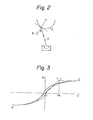
- a shielding plate 13 limits an incident angle of a vapor stream from a source 17. The incident angle herein indicates an angle 9, as shown in Fig. 2, defined by a vapor stream A entering a substrate surface C and a normal B from the substrate surface C.
- the shielding plate 13 shown in Fig. 1 has an aperture 14 which ensures that the vapor stream is deposited on the substrate surface C at a selected incident angle not exceeding 45°.
- the vaporized material substantially consisting of iron and nickel is denoted by 15.
- the ion-source 17 generates and accelerates ions and extracts an ion beam.
- the gas to be ionized is fed through a variable leak valve 19 and an introducing conduit 18.
- the electron beam evaporator is denoted by 16.
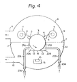
- the apparatus illustrated in Fig. 4 is provided with partition walls 21A, 21B, gas-feeding chambers 20A, 20B surrounded by the shielding plate 13, gas-conduits 22A and 22B for introducing the gas into the gas-feeding chambers 20A, 20B, and variable leak-valves 23A, 23B.
- the apparatuses described above are used for producing a perpendicular magnetic recording medium in accordance with the method of the present invention.
- the method for producing a perpendicular magnetic recording medium in accordance with the present invention is not limited to those described above.
- the vacuum deposition method utilized in the present invention may be any method including a resistance heating vaporization, an induction heating vaporization, an electron-beam vaporization, a laser-beam vaporization, and an arc-discharge vaporization.
- the electron-beam vaporization and the induction heating vaporization are preferable from the viewpoint of improving the magnetic properties, such as the coercive force and anisotropic field, and enhancing the deposition speed.
- the electron beam vapor deposition technique is most preferable from an industrial point of view, to enhance features such as adaptability and mass production.
- the vacuum deposition of the soft magnetic film substantially consisting of iron and nickel is carried out under the irradiation of an accelerated ion-beam.
- the ion-beam is applied to the position at which the deposition of the soft magnetic film occurs. It is possible thereby to form on the substrate having a low temperature, a soft magnetic film without cracks and having uniform and improved magnetic properties.
- the ion beam which is used for irradiation during growth of a soft magnetic film, consists of accelerated ions which are formed by ionizing such gases as hydrogen, ammonia, argon, helium, neon, krypton, and the like into monovalence, divalence, or higher valency.
- gases such as hydrogen, ammonia, argon, helium, neon, krypton, and the like into monovalence, divalence, or higher valency.
- An inert gas such as argon
- Reducing gases, such as hydrogen and ammonia are preferred alternatives.
- the acceleration energy of ions incident on the depositing position of a soft magnetic film is preferably in the range of from 200eV to 6keV, since within this range, the radiation by ions is highly effective and the organic polymer of the substrate is not thermally damaged.
- a more preferable range is from 500eV to 4keV, and the most preferable range is from lkeV to 3keV.
- the radiation density of the ion beam is preferably in the range of from luA/cm2 to 50mA/cm , since within this range, the radiation by ions is highly effective and the organic polymer of the base is not thermally damaged.
- a more preferable range is from 5 ⁇ A/cm 2 to 20mA/cm 2 , and the most preferable range is from 20pA/cm to 5mA/cm 2 .
- the radiation by ion beam may be continuous or intermittent, but is preferably continuous, since the effects desired by the radiation by ions can be easily attained.
- the entire depositing positions of a soft magnetic film are desirably irradiated with an ion beam.
- the radiation is particularly effective if it is carried out for a period including an initial stage of forming a soft magnetic film.
- the ion source used for producing the ion beam in accordance with the present invention is preferably a so-called plasma ion source, since an ion beam having a relatively high current is necessary for the radiation.
- the plasma ion source includes a plasma-generating chamber, an extraction electrode, which has an aperture, for extracting ions therethrough, and electrodes for rectifying the shape of an ion beam.
- the plasma ion source generally acts as follows.
- the element to be ionized or its compound is gasified and then introduced into the plasma generating chamber, and is ionized by a technique such as electron bombardment by a microwave discharge, electron oscillation, electron beam injection, and Penning discharge.
- the generated ions are extracted from the plasma generating chamber through the extraction aperture and, at the same time, accelerated under the electric field generated by the extraction electrode.
- the difference of the potential between the plasma and the substrate which is irradiated with ions acts as the acceleration energy.
- the radiation density of the ions can be varied by varying the ionization efficiency in the plasma generating chamber or by rectifying the shape of the ion beam which has been extracted.
- the gas introduced into the ion source should be maintained at a requisite minimum amount, preferably as small as possible, required for forming the ions, since the generation of cracks in the soft magnetic film can be thus prevented and the coercive force can be lessened.
- the amount of gas introduced into an ion source is usually monitored by the flow rate or pressure thereof in the vacuum chamber in which the ion source is contained.
- the requisite minimum amount of gas introduced into the ion source is determined by the gas-exhausting speed, and hence varies in accordance with the requirements of the respective apparatuses used for implementing the ion-beam formation.
- the temperature of the substrate is controlled, when the soft magnetic film is formed, by the holder with which the substrate is brought into contact.
- the holder is, for example, the main drum 3 shown in Fig. 1.
- the holder is brought into close contact with the rear surface of the substrate and the substrate is heated or cooled by the holder.
- thermal deformation of the substrate which consists of polymer is prevented, and an increase in the coercive force of the soft magnetic film due to stress caused by a difference in the thermal expansion coefficients between the substrate, an inorganic material film, and a soft magnetic film, during the formation of the soft magnetic film is also prevented. Therefore, a lower temperature at a holder, is more preferable.
- the ion-beam radiation is, also effective for vacuum- depositing a soft magnetic film onto a heated substrate.
- the temperature of the substrate during the formation of a soft magnetic film should be from -30°C to 180°C, preferably from -20°C to 150°C, more preferably, from -20°C to 130°C.
- the incident angle defined hereinabove is preferably 45 degrees or less, to lessen the coercive force of a soft magnetic film substantially consisting of iron and nickel. More preferably, the incident angle is 30 degrees or less.
- the soft magnetic film used in the present invention mainly comprises iron and nickel.
- iron to nickel there are two preferable ranges, most preferably in the range of from 10:90 to 30:70, and alternatively, in the range of from 40:60 to 60:40, for the purpose of lessening the coercive force and enhancing the permeability.
- One or more minor metal component(s) selected from the group consisting of manganese, molybdenum, chromium, and copper may be preferably added to the soft magnetic film for the purpose of lessening coercive force and enhancing the permeability.
- the amount of such minor metal component(s) may be at most 10% by weight.
- the addition of molybdenum and copper is particularly preferable since their effect on lessening the coercive force and enhancing the permeability is high.
- Preferred alloys with an additive(s) other than iron and nickel, all by weight proportion have the following approximate compositions: 21.2 iron/78.5 nickel/0.3 manganese; 15.7 iron/79.0 nickel/5.0 molybdenum/0.3 manganese; 18.0 iron/75.0 nickel/2.0 chromium/5.0 copper; 17.7 iron/78.5 nickel/3.8 chromium; 16.0 iron/80.0 nickel/4.0 molybdenum; and, 14.0 iron/77.0 nickel/5.0 copper/4.0 molybdenum.
- the recording and reproducing properties of the perpendicular magnetic recording medium are improved by enhancing a mutual action between the perpendicular magnetic film and the magnetic head.
- the soft magnetic film should exhibit a coercive force in a direction parallel to the film surface of preferably 20 Oe or less, more preferably 10 Oe or less.
- the soft magnetic film should have a thickness which is the optimum with regard to the mutual action between the perpendicular magnetic film and the magnetic head. Such a mutual action is attained by preferably controlling the thickness of a soft magnetic film so that the saturation magnetic moment per unit area thereof is at least a quarter, and at most ten times that of the perpendicular magnetic film. More preferably, the saturation magnetic moment of the soft magnetic film relative to that of the perpendicular magnetic film should be at least one third, and six times at most. The most preferred value is at least a half, and four times at most.
- the polymers appropriately used for the substrate in the present invention are: polyesters, such as polyethylene terephthalate, polyethylene napthalate, and polyethylene carboxylate; polyolefin, such as polyethylene, polypropylene, and polybutene; polymethyl methacrylate; polycarbonate; polysulfone; polyamide; aromatic polyamide; polyphenylene sulfide; polyphenylene oxide; polyamide-imide; polyimide; polyvinylchloride; polyvinylidenechloride; polyvinylidene fluoride; poly- tetrofluoro ethylene; cellulose acetate; methyl cellulose; ethyl cellulose; epoxy resin; polyurethane resin; mixture of any of those materials; and copolymers of any of these materials.
- polyesters such as polyethylene terephthalate, polyethylene napthalate, and polyethylene carboxylate
- polyolefin such as polyethylene, polypropylene, and polybutene
- polymethyl methacrylate polycarbon
- the biaxially oriented film, sheet, and the like have excellent flatness and shape stability, and hence are most appropriate for the base. Polyester, polyphenylene sulfide, and aromatic polyamide are most appropriate.
- the substrate can have any shape, such as a drum, disc, sheet, tape, card, and the like. There is no limit to the thickness of the substrate, but when the substrate is in the form of a sheet, a tape or a card, the thickness is preferably in the range of from 3 to 500 ⁇ m, particularly from 4 to 200 ⁇ m.
- the substrate used in the present invention may be subjected, prior to formation of the soft magnetic film, to various surface treatments or pretreatments to facilitate the bonding, improve the flatness, for coloring, anti-static treatment, imparting wear resistance, and the like.
- the perpendicular magnetic film having a magnetic anisotropy perpendicular to the substrate surface herein is defined as follows.
- An index is provided for representing the magnetic anisotropy in the direction perpendicular to the film surface, that is, magnetic anisotropy field Hk, and it is considered that the higher the value of the magnetic anisotropy field Hk, the more easily is the perpendicular magnetic film magnetized in the perpendicular direction and thus has more excellent characteristics.
- the origin is denoted by 0
- the ordinate indicates the magnetizing quantity M of a perpendicular magnetic film being magnetized
- the abscissa indicates an external magnetic field H being applied to the perpendicular magnetic film.
- the hysteresis loop shown in Fig. 3 represents the case wherein the external magnetic field H is applied in a direction parallel to the surface of a perpendicular magnetic recording film- sample.
- the magnetic anisotropy field Hk is equal to the value of the external magnetic field H at the point of intersection F formed by the tangent drawn from the origin O to the hysteresis loop and by the straight line drawn from the saturation magnetization point D in parallel to the axis of external magnetic field H.
- the hysteresis loop of only the perpendicular magnetic film, not including that of the soft magnetic film, can be obtained by a preliminary measurement of the latter loop, followed by measuring the hysteresis loop of the perpendicular magnetic film, and subtracting the hysteresis loop of the soft magnetic film from that of the perpendicular magnetic film.
- the magnetic film having a magnetic anisotropy field Hk of 2kOe or larger is usually referred to as the perpendicular magnetic film.
- a ferromagnetic metal such as cobalt, iron, and nickel, an alloy of any of these metals with another metal(s), a mixture of any of these metals and a metal oxide, and an oxide of any of these metals can be used in the present invention.
- an alloy of a ferromagnetic metal(s) and another metal(s) and a mixture of a ferromagnetic metal and metal oxide are preferred.
- Representative preferred alloys are cobalt-chromium alloy (c.f. USP No. 4,477,488), cobalt-rhodium, cobalt- zinc, and cobalt-iridium alloys (c.f. USP No. 4,486,498), a cobalt-molybdenum-vanadium alloy (c.f. USP No. 4,452,864) and a cobalt-chromium-vanadium alloy (c.f. USP No. 4,454,195). These alloys are well known. A representative preferred mixture is disclosed in EPC application No. 85.301944.6 filed by the present applicant.
- the perpendicular magnetic film is usually formed on a substrate by sputtering or vacuum-deposition.
- the method for forming an alloy film by sputtering is not appropriate for mass production, since the formation speed is low.
- the heating of a substrate up to a temperature of from 150 to 200°C is advisable for improving the magnetic properties of a perpendicular magnetic film.
- the method for forming an alloy film by vacuum deposition provides a high speed film formation, but it is difficult to maintain the composition in a uniform state during vacuum deposition.
- the heating of a substrate up to a temperature of from 150 to 300°C is advisable for improving the magnetic properties of a perpendicular magnetic film (c.f. USP No. 4,477,488).
- ferromagnetic metal is vacuum-deposited in gas containing oxygen, thereby enabling the formation, at a high speed, of a perpendicular magnetic film consisting of ferromagnetic metal and a metal oxide and having improved magnetic properties, without heating the substrate.
- the perpendicular magnetic film consisting of ferromagnetic metal and metal oxide is preferably used.
- this perpendicular magnetic film substantially consists of cobalt and cobalt oxide and/or iron and iron oxide, in the light of obtaining the desired magnetic properties.
- the cobalt oxide includes CoO, Co203 , CO 3 O 4 , and the like and also includes nonstoichiometric oxide and peroxide expressed by CoOx, x ranging between 0 and 2.
- Iron oxide includes FeO, Fe 203 Fe 3 O 4 , and the like and also includes nonstoichiometric oxide and peroxide expressed by FeOx, x ranging between 0 and 2.
- the perpendicular magnetic film may contain, in addition to cobalt, cobalt oxide, iron, and iron oxide, for example, nickel, copper, chromium, aluminum, carbon, silicon, vanadium, titanium, zinc, manganese, a metal oxide, a metal nitride, and a metal hydroxide, in such a content that the magnetic anisotropy in the perpendicular direction is not impeded.
- the thickness of the perpendicular magnetic film is not particularly limited but, practically, should be in the range of from 0.05 ⁇ m to 5 ⁇ m. A thickness in the range of from 0.1 ⁇ m to 2 ⁇ m is most preferred in the light of flexibility and head touch.
- the perpendicular magnetic film can be formed by such physical vapor deposition techniques as vacuum deposition, ion-plating, and sputtering.
- the vacuum deposition technique is particularly preferred, since the temperature rise of the substrate is small and the deposition speed is high.
- the pressure of gas media which contains oxygen, in the vicinity of the base is desirably in the range of from 1 x 10 -3 Torr to 5 x 10 -2 Torr, to improve the magnetic properties of the perpendicular magnetic film substantially consisting of cobalt and cobalt oxide and/or iron and iron oxide.
- the substrate is preferably cooled to a temperature of 50°C or less, to enhance the magnetic anisotropy field Hk of the perpendicular magnetic film.
- iron vapor and/or cobalt vapor move toward and arrive on the substrate at the incident angle defined above.
- the preferred incident angle of 45° or less described above for the soft magnetic film is also preferred for the perpendicular magnetic film, since the magnetic anisotropy field Hk is enhanced thereby.
- Such an incident angle is attained by providing a shielding plate which blocks vapor entering at an angle exceeding 45°.
- the pressure distribution in the vacuum chamber is such that the pressure increases in accordance with the distance from an exhaust outlet.
- the pressure in the vacuum chamber is an important factor for forming the perpendicular magnetic film.
- the pressure in the vicinity of the substrate mentioned above indicates a pressure measured at a linear distance of 500 mm or less from the center of the area at which a perpendicular magnetic film is formed.
- a method for producing a perpendicular magnetic recording medium having a structure comprising polymeric substrate, soft magnetic film and perpendicular magnetic film, is described hereinafter but the scope of the invention is not limited to the method described below.
- a strip film substrate consisting of a polymeric material, for example, polyethylene terephthalate, is disposed.
- An ingot having a weight proportion of iron and nickel of 17:83 is disposed in the recess of an electron-beam evaporator 16.
- the vacuum chamber 8, in which the ingot is disposed on the electron-beam evaporator 16, is exhausted through the respective exhaust outlets 11, 12 until the pressure of 1 x 10 4 Torr or less is obtained in the upper chamber 9 and the pressure of 5 x 10 -6 Torr or less is obtained in the lower chamber 10.
- argon gas is admitted to the ion-source 17 through the variable leak valve 19.
- the ion-source 17 is manipulated so that the argon ions arriving at the base 6 on the main drum 3 have an acceleration energy of lkeV and a radiation density of 200 PA/cm2.
- the substrate i.e., the polyethylene terephthalate film substrate mentioned above
- the soft magnetic film substantially consisting of iron and nickel is continuously formed, at a deposition rate of 10 um/minute up to a thickness of approximately 0.25 ⁇ m on the polyethylene terephthalate film substrate by means of the electron-beam, vacuum deposition.
- the main drum 3 which is brought into contact with the rear surface of the substrate, has a ground potential and is cooled to 20°C or less.
- the shielding plate 13 is disposed in such a manner that the iron and nickel vapor is incident upon the substrate at an incident angle of 45 degrees or less.
- the polyethylene terephthalate film substrate having a soft magnetic film deposited thereon is located on the coveying system shown in Fig. 4.
- the vacuum chamber 8, in which, for example, cobalt is disposed in the recess of the electron-beam evaporator 16, is exhausted through the exhaust outlets 11 and 12, until the pressure of 5 x 10 -4 Torr or less and the pressure in the vicinity of a substrate of 5 x 10 -5 Torr or less are attained in the upper chamber 9 and the lower chamber 10, respectively.
- a gas mixture of nitrogen gas and oxygen gas having a partial pressure ratio of 80:20 is admitted to the vicinity of the substrate through the variable leak valves 23A, 23B, so as to attain a predetermined pressure in the vicinity of the substrate, in the range of from 1 x 10 -3 Torr to 5 x 10 -2 Torr.
- the polyethylene terephthalate film substrate having a soft magnetic film preliminarily deposited thereon is driven to run, and a perpendicular magnetic film substantially consisting of cobalt and cobalt oxide is continuously formed on the soft magnetic film at a deposition rate of 10 pm/minute up to a thickness of approximately 0.25 pm by means of electron-beam, vacuum deposition.
- the main drum 3 which is brought into contact with the rear surface of the substrate, is cooled to 10°C or less.
- the shielding plate 13 is disposed in such a manner that the cobalt vapor is incident upon the substrate at an incident angle of 45 degrees or less.
- an addition/step for producing a lubricant layer or protective layer may be carried out.
- Such layers are used to improve the properties of the perpendicular magnetic recording medium, e.g., the sliding property relative to the magnetic head and guide system, wear resistance, and running-durability.
- a procedure for forming a back coating may be added.
- a 50 ⁇ 500 A thick layer of nonmagnetic metal or nonmagnetic oxide is interposed, because the soft magnetic film and the perpendicular magnetic film are magnetically isolated from one another, so that an apparent increase in coercive force of the soft magnetic film due to the presence of the perpendicular magnetic film is prevented.
- a nonmagnetic metal or oxide-layer having a thickness in 0 the range of from 50 to 500 A can be interposed between the soft magnetic film and the perpendicular magnetic film.
- the soft magnetic film substantially consisting of iron and nickel free of cracks and exhibiting a low coercive force, can be obtained even on the substrate kept to a low temperature, by means of vacuum deposition during which ion-beam radiation is carried out.
- the crystals of the soft magnetic film substantially consisting of iron and nickel are more strongly oriented, due to the vacuum-deposition during which the ion-beam radiation is carried out, such that the orientation of the (111) plane parallel to the film surface is intensified.
- a minor amount of the element, which is ionized to produce the ion beam, is incorporated into the soft magnetic film.
- the quantity of carbon atoms, which are contained in the soft magnetic film as impurities, is lessened by the ion-beam radiation during the vacuum-deposition. It is presumed, based on the facts observed as above, that the energy of the ions and the activation energy of the ions are effective for relaxing the internal stress of a soft magnetic film during growth, promoting the crystal orientation', and striking out the impurities, so that the soft magnetic film substantially consisting of iron and nickel and formed by vacuum deposition, is free of cracks and exhibits a low coercive force.
- the radiation by an ion beam is most effective, since, presumably, the sputtering yield of argon ions is relatively high and the quantity of the element incorporated in the film is small.
- the crystallization degree and crystal orientation of the soft magnetic film substantially consisting of Fe and Ni are enhanced.
- the quantity of an impurity, such as carbon, incorporated into the soft magnetic film during the vapor deposition is small, and the internal stress remaining in the film after the formation thereof is small.
- the perpendicular magnetic recording medium produced according to the present invention is free of cracks which cause drop-out, drop-in, and noise, and hence is uniform.
- the perpendicular magnetic recording medium also has a high recording and reproducing sensitivity due to improved magnetic properties.
- the orientation of (111) plane in a direction parallel to the film surface is intensified and a half value width of the (111) diffraction peak of 10° less can be attained.
- An impurity such as carbon, acts in the soft magnetic film to enhance the coercive force of the film, and hence, should not be incorporated therein if possible.
- the quantity of carbon atoms incorporated into the soft magnetic film is 0.2 atomic % or less, and hence the coercive force of the film is low.
- the perpendicular magnetic recording medium produced by the method of the present invention exhibits only slight wear and peel due to contact with the magnetic head and guide system, and hence, has an improved head-touch.
- the vacuum deposition and low substrate- temperature are advantageously combined so that a perpendicular magnetic recording medium is formed at a high speed on a plastic substrate which has a low heat-resistance.
- the perpendicular magnetic recording medium produced by the method of present invention can be broadly used for the magnetic recording of audio, video, and digital signals, in the form of, for example, a tape, a sheet, a card, a disc, and a drum.
- a vibration sample magnetometer (produced by Riken Denshi Co., Ltd., BHV-30) is used and a hysteresis loop is recorded by applying an external magnetic field parallel to the film surface of a sample.
- the coercive force is obtained from this hysteresis loop based on the definition given by JIS C-2561.
- the presence or absence of cracks in the soft magnetic film and the perpendicular magnetic film is detected by the following method.
- a soft magnetic film and a perpendicular magnetic film are observed by a metallurgical microscope (produced by Nippon Kogaku Co., Ltd., "OPTIPHOT") at a magnification of from 80 to 1000 times, and the presence or absence of cracks is detected.
- the diffraction pattern is measured by a reflection method, using a CuKa ray.
- a relative height of the diffraction peak from the (111) plane and a half-value width of this diffraction peak are measured and used as an index indicating the intensity of orientation of the (111) plane parallel to the film surface.
- An XPS X-ray photoelection spectroscopy
- ESCALAB5 type An XPS (X-ray photoelection spectroscopy) (produced by VG Scientific Limited, ESCALAB5 type) is used to measure the quantity of impurities in the film, and the quantity of an element which is ionized to form the ion beam and then incorporated in the film.
- the surface layer of a sample is etched by nitrogen ions and the sample is then subjected to measurement by XPS.
- a 50 ⁇ m thick biaxially oriented polyethylene terephthalate film was disposed in the conveying system of a strip film of the vacuum-deposition apparatus shown in Fig. 1.
- An ingot having a weight proportion of iron and nickel of 17:83 was disposed in the recess of an electron-beam evaporator 16.
- the vacuum chamber 8, in which the ingot was disposed on the electron-beam evaporator 16, was exhausted through the respective exhaust openings 11, 12 until a pressure of 1 x 10 4 Torr or less was obtained in the upper chamber 9 and a pressure of 5 x 10⁻⁶ Torr or less was obtained in the lower chamber 10.
- the argon gas was then admitted to the ion-source 17 through the variable leak valve 19.
- the ion-source 17 was manipulated so that the argon ions arriving at the base 6 on the main drum 3 exhibited a predetermined acceleration energy and radiation density.
- the base i.e., the polyethylene terephthalate film mentioned above, was driven to run at a predetermined speed.
- the ingot consisting of iron and nickel in a weight proportion of 17:83 was melted and vaporized by the electron-beam.
- An approximately 0.25 ⁇ m thick soft magnetic film was continuously formed at a deposition rate of 10 um/minute on the polyethylene terephthalate film by means of the electron-beam, vacuum-deposition.
- the potential of the main drum was ground.
- the shielding plate 13 was disposed in such a manner that the iron and nickel vapor was incident upon the base at an incident angle of 45 degrees or less.
- the electron-beam evaporator used was an EGL-110 type produced by Nippon Shinku Gijutsu Co., Ltd.
- the ion source used was a MIS-250 type produced by Nippon Denshi Co., Ltd.
- the coercive force and cracks of the latter film were measured.
- the X-ray diffractometry and the XP S measurement were carried out, that is their measurements were carried out for the soft magnetic film without the perpendicular magnetic film formed thereon.
- the polyethylene terephthalate film having a soft magnetic film deposited thereon was located on the conveying system shown in Fig. 4. Cobalt was disposed in the recess of the electron-beam evaporator 16.
- the vacuum chamber 8, in which cobalt was disposed on the electron-beam evaporator 16, was exhausted through the exhaust openings 11 and 12 until a pressure of 5 x 1 0- 4 Torr or less and a pressure in the vicinity of the substrate of 5 x 10 -5 Torr or less were attained in the upper chamber 9 and the lower chamber 10, respectively
- a gas mixture of nitrogen gas and oxygen gas having the partial pressure ratio of 85:15 was admitted into the vicinity of a substrate through the variable leak valves 23A, 23B, so as to attain a predetermined pressure in the vicinity of the substrate of 5 x 10 -3 Torr. After attaining this pressure, the polyethylene terephthalate film having a soft magnetic film preliminarily deposited thereon was driven to run.
- Cobalt was melted and vaporized by the electron-beam.
- An approximately 0.25 ⁇ m perpendicular magnetic film was continuously formed, at a deposition rate of 10 pm/minute on the soft magnetic film by means of electron-beam, vacuum-deposition.
- the shielding plate 13 was disposed in such a manner that the cobalt vapor was incident upon the substrate at an incident angle of 45 degrees or less.
- the electron-beam evaporator used was the EGL-110 type produced by Nippon Shinku Gijutsu Co., Ltd.
- the acceleration energy of an ion beam and the ion radiation density were varied as follows.
- Example 1 the acceleration energy of an ion beam was 0.5 keV and the radiation density was 200 ⁇ A/cm 2 at the formation of a soft magnetic film.
- Example 2 the acceleration energy of an ion beam was 1.0 keV and the radiation density was 250 pA/cm 2 at the formation of a soft magnetic film.
- Example 3 the acceleration energy of an ion beam was 0.3 keV and the radiation density was 200 ⁇ A/cm 2 at the formation of a soft magnetic film.
- Example 1-3 the power input to the electron-beam evaporator was 4 kW (constant) for the formation of both the soft magnetic film and the perpendicular magnetic film.
- Examples 1 and 2 cracks were not generated in the soft magnetic films, a coercive force of the soft magnetic films was less than 10 Oe, and cracks were not generated in the perpendicular magnetic films formed on the soft magnetic films.
- Example 3 although the coercive force of the soft magnetic film was relatively high, since the acceleration energy of an ion beam was somewhat low, cracks were not found in the soft magnetic film.
- Comparative Example 1 in which the vacuum-deposition was an ordinary one without the ion-beam radiation, a number of fine cracks were generated in the soft magnetic film and the film had a whitish, dull appearance. In addition, the coercive force thereof was high. The cracks were not covered even after the formation of the perpendicular magnetic film, and cracks appeared on the top surface of the medium.
- the ion-beam radiation improved the crystal orientation of the (111) plane of the soft magnetic films and lessened the quantity of impurity-carbon atoms contained in the soft magnetic films.
- the soft magnetic films irradiated with an ion beam during their formation contained approximately 0.6% of argon therein.
- the argon content of the soft magnetic film not irradiated with the ion beam during the formation thereof was less than the lower limit of detection by XPS.
- Example 4 the procedure of Example 2 was repeated except that iron was used as the evaporation material for forming a perpendicular magnetic film.
- Example 5 the procedure of Example 2 was repeated except that the evaporation material, in which the weight proportion of cobalt to iron was 80:20, was used for forming a perpendicular magnetic film.
- Example 2 The procedure of Example 2 was repeated except that neon gas was introduced in the ion source and converted to an ion beam.
- the coercive force of the soft magnetic film was low, and no cracks were generated in the soft magnetic film and the perpendicular magnetic film as shown in Table 2.
- Example 1 The procedure of Example 1 was repeated except that the substrate was not irradiated with the ion bean during formation of a soft magnetic film, and the temperature of the main drum, which was brought into close contact with the rear surface of the base, was 150°C.
- the coercive force was less than the case where the main drum-temperature was 10°C but was not satisfactorily low.
- the generation of cracks could not be prevented.
- the cracks did not disappear even after forming the perpendicular magnetic film on the soft magnetic film.
- Example 2 The procedure of Example 2 for forming a soft magnetic film was repeated except that the substrate was a biaxially oriented polyimide film. On this soft magnetic film a perpendicular magnetic film substantially consisting of cobalt and chromium were successively formed.
- the sputtering target was made of alloy containing cobalt and chromium at a weight ratio of 83:17.
- the vacuum chamber was exhausted to 1 x 10 -6 Torr or less and then argon gas was admitted to the vacuum chamber until a pressure of 2 x 10 -3 Torr was obtained.
- Negative voltage was applied to the sputtering target to generate a glow discharge, thereby forming a perpendicular magnetic film on the substrate in the form of a cut sheet, which was located in front of the sputtering target, and which was preliminarily provided with the soft magnetic film.
- the deposition rate of the perpendicular magnetic film was 0.3 um/minute and the film thickness was 0.25 um.
- the sputtering device used was EVP-10758 type produced by Niommen Anelva Co., Ltd. and cracks were not generated in the soft magnetic film and the perpendicular magnetic film.
Landscapes
- Manufacturing Of Magnetic Record Carriers (AREA)
- Physical Vapour Deposition (AREA)
- Crystals, And After-Treatments Of Crystals (AREA)
- Magnetic Record Carriers (AREA)
Applications Claiming Priority (2)
| Application Number | Priority Date | Filing Date | Title |
|---|---|---|---|
| JP12481/85 | 1985-01-28 | ||
| JP1248185 | 1985-01-28 |
Publications (2)
| Publication Number | Publication Date |
|---|---|
| EP0190854A2 true EP0190854A2 (de) | 1986-08-13 |
| EP0190854A3 EP0190854A3 (de) | 1988-07-20 |
Family
ID=11806582
Family Applications (1)
| Application Number | Title | Priority Date | Filing Date |
|---|---|---|---|
| EP86300514A Withdrawn EP0190854A3 (de) | 1985-01-28 | 1986-01-27 | Methode zur Herstellung von einem Träger mit senkrechter magnetischer Aufzeichnung |
Country Status (2)
| Country | Link |
|---|---|
| EP (1) | EP0190854A3 (de) |
| JP (1) | JPS61276124A (de) |
Cited By (2)
| Publication number | Priority date | Publication date | Assignee | Title |
|---|---|---|---|---|
| EP0351815A3 (de) * | 1988-07-20 | 1990-12-27 | Kanegafuchi Kagaku Kogyo Kabushiki Kaisha | Aufzeichnungsträger für senkrechte magnetische Aufzeichnung, Verfahren zu seiner Herstellung und Verfahren zur Aufnahme und Wiedergabe |
| US7704321B2 (en) | 2002-05-13 | 2010-04-27 | Rutgers, The State University | Polycrystalline material having a plurality of single crystal particles |
Families Citing this family (2)
| Publication number | Priority date | Publication date | Assignee | Title |
|---|---|---|---|---|
| JP4657916B2 (ja) * | 2003-05-14 | 2011-03-23 | ラトガース,ザ ステート ユニバーシティ | 単結晶様物質 |
| KR100768548B1 (ko) | 2005-01-04 | 2007-10-18 | 이곤구 | 고밀도 플라즈마 이온주입에 의한 표면처리 장치 |
Family Cites Families (2)
| Publication number | Priority date | Publication date | Assignee | Title |
|---|---|---|---|---|
| JPS5891B2 (ja) * | 1977-09-30 | 1983-01-05 | 俊一 岩崎 | 磁気記録媒体 |
| JPS584915A (ja) * | 1981-07-01 | 1983-01-12 | Hitachi Ltd | 磁性薄膜の製造方法 |
-
1986
- 1986-01-27 EP EP86300514A patent/EP0190854A3/de not_active Withdrawn
- 1986-01-28 JP JP61016450A patent/JPS61276124A/ja active Pending
Cited By (2)
| Publication number | Priority date | Publication date | Assignee | Title |
|---|---|---|---|---|
| EP0351815A3 (de) * | 1988-07-20 | 1990-12-27 | Kanegafuchi Kagaku Kogyo Kabushiki Kaisha | Aufzeichnungsträger für senkrechte magnetische Aufzeichnung, Verfahren zu seiner Herstellung und Verfahren zur Aufnahme und Wiedergabe |
| US7704321B2 (en) | 2002-05-13 | 2010-04-27 | Rutgers, The State University | Polycrystalline material having a plurality of single crystal particles |
Also Published As
| Publication number | Publication date |
|---|---|
| JPS61276124A (ja) | 1986-12-06 |
| EP0190854A3 (de) | 1988-07-20 |
Similar Documents
| Publication | Publication Date | Title |
|---|---|---|
| US4382110A (en) | Magnetic recording medium | |
| EP0054269B1 (de) | Magnetischer Senkrechtaufzeichnungsträger, sein Herstellungsverfahren und ein Zerstäubungsapparat | |
| EP0132398B1 (de) | Verfahren und Vorrichtung zur Erzeugung von Ionenstrahlen | |
| EP0122030B1 (de) | Magnetisches Aufzeichnungsmedium und Herstellungsverfahren für ein derartiges Medium | |
| EP0035870B1 (de) | Verfahren zur Herstellung eines magnetischen Aufzeichnungsmediums | |
| JPH0318254B2 (de) | ||
| US4673610A (en) | Magnetic recording medium having iron nitride recording layer | |
| CA1162113A (en) | Process for producing magnetic recording medium | |
| US4990361A (en) | Method for producing magnetic recording medium | |
| JPH033369B2 (de) | ||
| JPS61276124A (ja) | 垂直磁気記録媒体の製造方法 | |
| JPS6367328B2 (de) | ||
| JP2883334B2 (ja) | 磁気記録媒体の製造方法 | |
| US4724156A (en) | Method of manufacturing magnetic recording medium | |
| JPH035644B2 (de) | ||
| JPS61133030A (ja) | 磁気記録媒体の製造方法 | |
| JP2752179B2 (ja) | 垂直磁気記録媒体及びその製造方法 | |
| JPH0334619B2 (de) | ||
| CA1184881A (en) | Perpendicular magnetic recording medium, method for producing the same, and sputtering device | |
| JPH04259204A (ja) | 磁気記録媒体の製造方法 | |
| JPH033743B2 (de) | ||
| JPH0120495B2 (de) | ||
| JPS6037526B2 (ja) | 磁気記録媒体の製造方法 | |
| JPH0648526B2 (ja) | 磁気ヘッドの製造方法 | |
| JPS6145290B2 (de) |
Legal Events
| Date | Code | Title | Description |
|---|---|---|---|
| PUAI | Public reference made under article 153(3) epc to a published international application that has entered the european phase |
Free format text: ORIGINAL CODE: 0009012 |
|
| AK | Designated contracting states |
Kind code of ref document: A2 Designated state(s): DE FR GB NL |
|
| PUAL | Search report despatched |
Free format text: ORIGINAL CODE: 0009013 |
|
| AK | Designated contracting states |
Kind code of ref document: A3 Designated state(s): DE FR GB NL |
|
| RHK1 | Main classification (correction) |
Ipc: G11B 5/85 |
|
| STAA | Information on the status of an ep patent application or granted ep patent |
Free format text: STATUS: THE APPLICATION IS DEEMED TO BE WITHDRAWN |
|
| 18D | Application deemed to be withdrawn |
Effective date: 19890123 |
|
| RIN1 | Information on inventor provided before grant (corrected) |
Inventor name: AKAMATSU, TAKAYOSHI Inventor name: OKA, TETHUO Inventor name: HAYASHI, KENJI |