EP0190923B1 - Optische Faser mit mehreren Windungen als akustooptischer Frequenzschieber - Google Patents
Optische Faser mit mehreren Windungen als akustooptischer Frequenzschieber Download PDFInfo
- Publication number
- EP0190923B1 EP0190923B1 EP86300754A EP86300754A EP0190923B1 EP 0190923 B1 EP0190923 B1 EP 0190923B1 EP 86300754 A EP86300754 A EP 86300754A EP 86300754 A EP86300754 A EP 86300754A EP 0190923 B1 EP0190923 B1 EP 0190923B1
- Authority
- EP
- European Patent Office
- Prior art keywords
- fiber
- acoustic
- rod
- frequency
- frequency shifter
- Prior art date
- Legal status (The legal status is an assumption and is not a legal conclusion. Google has not performed a legal analysis and makes no representation as to the accuracy of the status listed.)
- Expired - Lifetime
Links
- 239000013307 optical fiber Substances 0.000 title claims abstract description 35
- 239000000835 fiber Substances 0.000 claims abstract description 243
- 230000003287 optical effect Effects 0.000 claims abstract description 30
- 238000004804 winding Methods 0.000 claims abstract description 12
- 230000001902 propagating effect Effects 0.000 claims description 18
- 238000005253 cladding Methods 0.000 claims description 8
- 239000007787 solid Substances 0.000 claims description 8
- 238000000034 method Methods 0.000 claims description 6
- 230000010287 polarization Effects 0.000 description 35
- 230000008878 coupling Effects 0.000 description 22
- 238000010168 coupling process Methods 0.000 description 22
- 238000005859 coupling reaction Methods 0.000 description 22
- 239000011295 pitch Substances 0.000 description 19
- 230000006835 compression Effects 0.000 description 10
- 238000007906 compression Methods 0.000 description 10
- 239000000463 material Substances 0.000 description 7
- 238000010897 surface acoustic wave method Methods 0.000 description 7
- 230000000694 effects Effects 0.000 description 5
- 230000003068 static effect Effects 0.000 description 4
- 230000008859 change Effects 0.000 description 3
- 230000008602 contraction Effects 0.000 description 3
- 230000005684 electric field Effects 0.000 description 3
- 238000005259 measurement Methods 0.000 description 3
- 230000000737 periodic effect Effects 0.000 description 3
- 230000000644 propagated effect Effects 0.000 description 3
- 230000004044 response Effects 0.000 description 3
- 238000012546 transfer Methods 0.000 description 3
- XLOMVQKBTHCTTD-UHFFFAOYSA-N Zinc monoxide Chemical compound [Zn]=O XLOMVQKBTHCTTD-UHFFFAOYSA-N 0.000 description 2
- 238000004458 analytical method Methods 0.000 description 2
- 238000013459 approach Methods 0.000 description 2
- 230000008901 benefit Effects 0.000 description 2
- 230000001186 cumulative effect Effects 0.000 description 2
- 230000007423 decrease Effects 0.000 description 2
- 238000010586 diagram Methods 0.000 description 2
- 230000003993 interaction Effects 0.000 description 2
- 229910013637 LiNbO2 Inorganic materials 0.000 description 1
- VYPSYNLAJGMNEJ-UHFFFAOYSA-N Silicium dioxide Chemical compound O=[Si]=O VYPSYNLAJGMNEJ-UHFFFAOYSA-N 0.000 description 1
- 239000011358 absorbing material Substances 0.000 description 1
- 230000001154 acute effect Effects 0.000 description 1
- 238000004891 communication Methods 0.000 description 1
- 238000010276 construction Methods 0.000 description 1
- 230000003247 decreasing effect Effects 0.000 description 1
- 230000001419 dependent effect Effects 0.000 description 1
- 238000011161 development Methods 0.000 description 1
- 229920006335 epoxy glue Polymers 0.000 description 1
- 239000003292 glue Substances 0.000 description 1
- 230000006872 improvement Effects 0.000 description 1
- HFGPZNIAWCZYJU-UHFFFAOYSA-N lead zirconate titanate Chemical compound [O-2].[O-2].[O-2].[O-2].[O-2].[Ti+4].[Zr+4].[Pb+2] HFGPZNIAWCZYJU-UHFFFAOYSA-N 0.000 description 1
- GQYHUHYESMUTHG-UHFFFAOYSA-N lithium niobate Chemical compound [Li+].[O-][Nb](=O)=O GQYHUHYESMUTHG-UHFFFAOYSA-N 0.000 description 1
- 238000004519 manufacturing process Methods 0.000 description 1
- 239000002480 mineral oil Substances 0.000 description 1
- 235000010446 mineral oil Nutrition 0.000 description 1
- 238000003825 pressing Methods 0.000 description 1
- 239000000126 substance Substances 0.000 description 1
- 239000011787 zinc oxide Substances 0.000 description 1
Images


Classifications
-
- G—PHYSICS
- G02—OPTICS
- G02F—OPTICAL DEVICES OR ARRANGEMENTS FOR THE CONTROL OF LIGHT BY MODIFICATION OF THE OPTICAL PROPERTIES OF THE MEDIA OF THE ELEMENTS INVOLVED THEREIN; NON-LINEAR OPTICS; FREQUENCY-CHANGING OF LIGHT; OPTICAL LOGIC ELEMENTS; OPTICAL ANALOGUE/DIGITAL CONVERTERS
- G02F2/00—Demodulating light; Transferring the modulation of modulated light; Frequency-changing of light
- G02F2/02—Frequency-changing of light, e.g. by quantum counters
-
- G—PHYSICS
- G02—OPTICS
- G02F—OPTICAL DEVICES OR ARRANGEMENTS FOR THE CONTROL OF LIGHT BY MODIFICATION OF THE OPTICAL PROPERTIES OF THE MEDIA OF THE ELEMENTS INVOLVED THEREIN; NON-LINEAR OPTICS; FREQUENCY-CHANGING OF LIGHT; OPTICAL LOGIC ELEMENTS; OPTICAL ANALOGUE/DIGITAL CONVERTERS
- G02F1/00—Devices or arrangements for the control of the intensity, colour, phase, polarisation or direction of light arriving from an independent light source, e.g. switching, gating or modulating; Non-linear optics
- G02F1/01—Devices or arrangements for the control of the intensity, colour, phase, polarisation or direction of light arriving from an independent light source, e.g. switching, gating or modulating; Non-linear optics for the control of the intensity, phase, polarisation or colour
- G02F1/0128—Devices or arrangements for the control of the intensity, colour, phase, polarisation or direction of light arriving from an independent light source, e.g. switching, gating or modulating; Non-linear optics for the control of the intensity, phase, polarisation or colour based on electro-mechanical, magneto-mechanical, elasto-optic effects
- G02F1/0131—Devices or arrangements for the control of the intensity, colour, phase, polarisation or direction of light arriving from an independent light source, e.g. switching, gating or modulating; Non-linear optics for the control of the intensity, phase, polarisation or colour based on electro-mechanical, magneto-mechanical, elasto-optic effects based on photo-elastic effects, e.g. mechanically induced birefringence
- G02F1/0134—Devices or arrangements for the control of the intensity, colour, phase, polarisation or direction of light arriving from an independent light source, e.g. switching, gating or modulating; Non-linear optics for the control of the intensity, phase, polarisation or colour based on electro-mechanical, magneto-mechanical, elasto-optic effects based on photo-elastic effects, e.g. mechanically induced birefringence in optical waveguides
Definitions
- the present invention relates to acousto-optic frequency shifters, and particularly to fiber optic frequency shifters utilizing surface acoustic waves or bulk acoustic waves.
- Optical frequency shifting is typically based upon the Doppler effect, i.e., the change in frequency due to relative movement between the source and observer.
- the frequency becomes higher and the wavelength shorter when the source is moving towards the observer, and the frequency becomes lower and the wavelength higher when the source is moving away from the observer.
- the Doppler effect has been used in bulk optics to cause frequency shifts in light waves reflected from wave fronts of acoustic waves propagating through optically transparent bulk media.
- the areas of compression and rarefaction caused by the traveling acoustic wave change the index of refraction in the bulk media so that the incoming light is reflected and/or refracted. Movement of the acoustic wave fronts causes a Doppler shift in the reflected and refracted light, such that the light is shifted in frequency by an amount equal to the frequency of the acoustic wave.
- a standing pressure wave in each cylinder resulted when the cylinders were excited with sinusoidal signals to cause elasto-optic coupling between the polarization modes of the fiber, thereby creating side bands above and below the optical carrier.
- Each cylinder generated one side band that was in phase and another that was out of phase with the side bands created by the other cylinder, such that one side band was strengthened and the other cancelled.
- the Nosu device thus functions by applying pressure to the fiber at discrete intervals along the fiber, specifically at intervals of three-quarters beat length of the fiber.
- the maximum frequency shift obtainable with the Nosu device is equal to the maximum rate which the PZT cylinders can be practically driven.
- the amount of power coupled between polarization modes at each coupling point -- i.e., at each PZT cylinder -- is quite small, and thus, to couple a significant amount of power a large number of these PZT cylinders would be required, yielding a quite unwieldy and generally impractical device for use in fiber optic systems.
- an alternative approach to frequency shifting is to launch an actual acoustic wave (either a surface wave or bulk wave), for propagation longitudinally along the length of the optical fiber.
- This approach has the advantage of providing a continuous, virtually infinite, number of coupling points which travel along the length of the fiber, as opposed to the discrete static coupling points at spaced intervals of the Nosu device.
- actual acoustic waves can be generated at a frequency which is higher than the PZT cylinders of Nosu can be driven, and thus, such actual acoustic wave devices are capable of greater amounts of frequency shift than the Nosu device.
- acousto-optic frequency shifters which utilize actual acoustic waves is that, for maximum coupling between modes, the acoustic wavelength should be equal to the fiber beat length.
- the minimum beat length is on the order of 1 mm.
- An acoustic wavelength of 1 mm corresponds to an acoustic frequency of about 1-5 MHz. Accordingly, there is a need in the art for a fiber optic frequency shifter which utilizes actual acoustic waves, but avoids this limitation such that the maximum possible frequency shift is not restricted by the beat length of the fiber.
- a fiber optic frequency shifter which positions an acoustic transducer relative to an optical fiber such that the wave fronts of the acoustic wave acoustically contact the fiber at an angle of incidence which is less than 90° and greater than 0°.
- the wavelength of the acoustic wave is substantially equal to the beat length of the optical fiber times the sine of the angle of incidence.
- the angle of incidence can be chosen such that the shorter wavelengths of high frequency acoustic waves can be matched with the beat length of the fiber.
- the maximum possible frequency shift can be substantially increased.
- the present invention provides an improvement on the basic concept described in European patent application No. 85300904.1 by providing a compact acousto-optic frequency shifter which achieves a large shift in the optical frequency while utilizing substantially all of the energy from the acoustic signal.
- a fiber optic frequency shifter comprising an acoustic conducting medium for propagating an acoustic wave; and an optical fiber having first and second modes which propagate light along a central axis at first and second velocities, respectively, said fiber being wound around said acoustic conducting medium to provide a plurality of turns of said fiber in which at least a portion of the fiber in each of said turns is placed in acoustic contact with said medium, each said portion of said fiber being positioned such that the central axis of the fiber in each portion is at an angle of incidence greater than 0° and less than 90° relative to the direction of propagation of said acoustic wave when said shifter is in use.
- the invention also provides a method of shifting the frequency of an optical signal, comprising the steps of propagating said optical signal at a first frequency through a plurality of turns of an optical fiber having a central axis and two modes of propagation, said fiber being wound with at least a portion of each of said turns in acoustic contact with an acoustic conducting medium; and directing an acoustic signal along said acoustic conducting medium to contact said portions of said turns such that the angle of incidence of the wave fronts of said acoustic signal with respect to the central axis of the fiber is greater than 0° and less than 90°, said acoustic signal stressing said fiber to cause optical energy of said optical signal propagating in one of said modes to be transferred to the other of said modes and shifted in frequency to a second frequency.
- the present invention comprises an optical fiber and an acoustic conducting medium for propagation of an acoustic signal.
- the acoustic medium is shaped as a rod, and the acoustic signal propagates longitudinally down the rod.
- the optical fiber is wound around the rod with plural turns such that the central axis of the fiber is at an angle relative to the wave fronts of the acoustic signal.
- this angle is referred to as the "angle of incidence.”
- the optical fiber is placed in acoustic contact with the rod for at least a portion of a plurality of turns, preferably each turn of the fiber, although it is preferable to provide continuous acoustic contact throughout the plural turns of the fiber.
- the angle of the fiber with respect to the wave fronts of the acoustic signal is chosen such that the wavelength of the acoustic signal is substantially equal to the beat length of an optical signal in the optical fiber times the sine of the angle of incidence.
- the optical fiber has physical parameters selected to cause an optical signal propagating therein to propagate in one or both of two propagation modes.
- the propagation modes may comprise the two polarization modes of a single mode birefringent optical fiber or the first and second order modes of a non-birefringent optical fiber.
- the acoustic wave may comprise either a bulk wave or a surface wave.
- a bulk acoustic wave traveling through the rod or a surface acoustic wave traveling on the rod causes undulations of the surface of the rod which acoustically contact the fiber and cause time-varying stresses in the fiber at each point of acoustic contact.
- a particular point of stress may be considered as non-time varying but traveling down the fiber with a propagation phase velocity dependent on the angle of incidence.
- the stresses cause energy to be transferred between the two modes of propagation of the optical signal.
- the multiple turns of fiber result in a substantially greater amount of energy transferred than would be transferred if the acoustic wave were to propagate along a single straight fiber.
- the fiber is wound on the acoustic medium such that the angle of incidence of the acoustic wave with the optical fiber is constant.
- the acousto-optic frequency shifter is responsive to a relatively narrow range of acoustic frequencies.
- the angle of incidence of the acoustic wave on the optical fiber can be varied by winding different portions of the fiber at different pitches relative to the direction of propagation of the acoustic wave.
- portions of the optical fiber can be made responsive to different acoustic frequencies.
- the winding pitch can be made linearly variable to provide a broadband frequency shifter.
- the winding pitch can be varied at discrete intervals to provide a frequency shifter responsive to discrete acoustic frequencies.
- the frequency shifter of the present invention utilizes a birefringent single mode optical fiber 10, having a central core 12 of relatively high index of refraction and a surrounding cladding 14 of relatively low index of refraction, as shown in Figure 1.
- a birefringent fiber has two orthogonal principle axes of birefringence, each of which corresponds to a polarization mode or optical path through the fiber. These axes are labelled X and Y in Figure 1. Light which is linearly polarized along either of these two axes will remain linearly polarized as it propagates down the fiber. In general, light of any polarization can be regarded as a superposition of these two linearly polarized modes.
- the two polarization modes of birefringent single mode optical fiber propagate light at slightly different velocities. Therefore, the phase of light in the X-axis mode will change relative to that in the Y-axis mode as the light propagates down the fiber.
- the distance, measured longitudinally along the fiber, required for light in one mode to separate in phase by 360° relative to light in the other mode is commonly referred to as the "beat length" of the fiber.
- the fiber 10 of the preferred embodiment is a high birefringence fiber having a beat length on the order of 1 mm.
- One common technique for fabricating high birefringence fibers is to draw the fiber such that the core has an elliptical shape, as illustrated by the core 12 in Figure 1.
- High birefringence fibers are advantageous in that the polarization modes are well defined, and thus the polarization of the applied light will be maintained over relatively long lengths of fiber, without significant coupling of light between the polarization modes.
- the polarization modes of a high birefringence fiber may be viewed as independent optical paths through the fiber, which are normally uncoupled such that light is not transferred between them.
- selective coupling of light between the polarization modes of a birefringent single mode fiber may be achieved by applying a force to the birefringent fiber at an angle of about 45° relative to the principle axes of birefringence. Such force may be applied by squeezing the fiber between two anvils or plates on opposing sides of the fiber.
- Figure 2 schematically depicts a ridge structure 20 comprising plural ridges 22, 24, 26 at spaced intervals.
- the fiber 10 is disposed between the ridges 22, 24, 26 and a base block 28, so that the fiber 10 may be squeezed therebetween.
- Application of force to the ridge structure 20 in a direction normal to the axes of the the fiber 10 perturb the axes of birefringence at each of the ridges 22, 24, 26 and provides alternate stressed and unstressed regions along the fiber 10 which cause coupling between the two polarization modes of the fiber 10.
- the alternate stressed and unstressed regions provided by the ridge structure 20 of Figure 2 may be alternatively provided by an actual traveling acoustic wave, such as the acoustic wave 30 of Figure 3, which is launched to propagate longitudinally along the central axis of the fiber 10.
- the periodicity of the traveling acoustic wave 30 provides alternating regions of compression and rarefaction so as to provide corresponding alternating stressed and unstressed regions in the fiber, and thus, cause coupling between the polarization modes of the fiber.
- the wavelength of the acoustic wave 30 be selected such that it is equal to the beat length of the fiber.
- each of the alternating regions of compression and rarefaction will then be one-half beat length in length, and thus, each of the alternating stressed and unstressed regions will also be one-half beat length in length.
- the acoustic wave 30 of Figure 3 by providing alternating half beat length stressed and unstressed regions along the fiber, cumulatively couples light between the polarization modes of the fiber in much the same manner as the half beat length ridges 22, 24, 26 of Figure 2.
- cumulative coupling will also occur if the wavelength is an odd multiple of beat lengths.
- the fiber stress pattern produced by the traveling acoustic wave 30 of Figure 3 travels down the fiber.
- Such travel of the stress pattern causes the light coupled from one polarization mode to the other to be shifted in frequency much as light from a moving source is Doppler shifted.
- the optical carrier wave and the acoustic wave are heterodyned such that the acoustic frequency and the optical carrier frequency combine both additively and subtractively to provide side bands at the sum and difference frequencies.
- the acoustic wave propagates in the same direction as the light, light coupled from the faster polarization mode to the slower polarization mode is upshifted in frequency, while light propagating from the slower polarization mode to the faster polarization mode is downshifted in frequency. If the acoustic wave propagates in a direction opposite to that of the optical carrier, these relationships are reversed, so that light coupled from the faster mode to the slower mode is downshifted, while light coupled from the slower mode to the faster mode is upshifted.
- Frequency shifted coupling requires that the acoustic wave be properly phased matched to the beat pattern of the optical modes in the fiber.
- phase matching occurs when the acoustic wavelength, as measured along the axis of the fiber (rather than the direction of propagation of the acoustic wave), is equal to the beat length of the fiber.
- the frequency shifted coupling of light between the polarization modes may be examined mathematically by representing the light in the fast optical mode as cos( ⁇ t - k1z), where ⁇ is the angular frequency of the light, t is time, and z is the distance along the fiber axis.
- the acoustic wave may be represented as cos( ⁇ a t - k a z), where ⁇ a is the angular frequency of the acoustic wave.
- the interaction of these two waves leads to a product term proportional to: 1 ⁇ 2 ⁇ cos[( ⁇ + ⁇ a )t - (k1+k a )Z ⁇ + cos[( ⁇ - ⁇ a )t - (k1-k a )Z ⁇ (3)
- the second term of Expression 3 does not satisfy the phase matching condition of Equation 2, and thus, it is expected that the signal represented by this term will die away.
- the first term is phase matched to the slow mode, in accordance with expression (2), and explicitly indicates that the slow mode is upshifted.
- the expression for the resulting interaction is: 1 ⁇ 2 ⁇ cos[( ⁇ - ⁇ a )t - (k2-k a )Z ⁇ + cos[( ⁇ + ⁇ a)t - (k2+k a )Z ⁇ (4)
- the upper side band will be contained in one polarization, and the lower side band will be contained in the other.
- the desired side band can be selected by passing the output light through a polarizer.
- phase matching requirements indicate that, for an acoustic wave propagating longitudinally down the fiber with the wave fronts normal to the fiber axis, the acoustic wave frequency should be such that its wavelength is equal to the fiber beat length. Since fiber beat lengths are typically on the order 1 mm or more, the maximum available frequency shift from such longitudinally propagating acoustic wave is on the order of only a few megahertz.
- Figure 4 illustrates a frequency shifter which circumvents this limitation by positioning an acoustic transducer 40 to produce an acoustic wave 42, which propagates in a direction, e.g., as indicated by the arrow 43, which is at an angle to the central axis 48 of a high birefringence single mode optical fiber 46.
- Such positioning causes the wave fronts 44 of the wave 42 to be directed to acoustically contact the highly birefringent single mode optical fiber 46 at an angle ⁇ , referred to herein as "the angle of incidence.”
- the term "angle of incidence is defined as the acute angle between a wave front of an acoustic wave impinging on the fiber and the longitudinal central axis 48 of that fiber.
- the wavelength ⁇ a (which is measured in the direction of propagation 43) of the acoustic wave 44 and the angle of incidence, ⁇ , are preferably selected such that adjacent wave fronts 44 are spaced by one fiber beat length, L, which is measured in a direction along the fiber axis 48.
- This beat length spacing of the wave fronts 44 satisfies the phase matching conditions set forth above, and thus, the component of acoustic propagation along the fiber axis 48 will satisfy Equation 2, above.
- This arrangement permits the use of much shorter acoustic wavelengths, and thus, much higher acoustic frequencies than with a longitudinally propagating acoustic wave, while still satisfying the phase matching condition.
- Equation 5 may be rewritten in terms of the acoustic frequency ⁇ a , as follows: where V a is the propagation velocity of the acoustic wave in the direction 43.
- Figure 6 graphically illustrates the relationship between the acoustic frequency and the angle of incidence, and shows that for very small angles of incidence (e.g., a few degrees or a fraction of a degree), the acoustic frequency utilized may be quite high. Note that the acoustic frequency is at a minimum when ⁇ equals 90° (i.e., when the acoustic wave fronts are normal to the fiber). By way of example, an angle of incidence of 3° would permit use of an acoustic frequency of 95 MHz for a fiber having a 1 mm beat length.
- the device of Figure 4 may also be analyzed in terms of the "propagation phase velocity" of the acoustic wave.
- the term "propagation phase velocity,” as used herein, is defined as the velocity, measured along a particular line of measurement (e.g., the direction 43 or axis 48), with which the intersection of a wave front (e.g., one of the wave fronts 44) and that axis of measurement move. Thus, for a particular wave front 44, that wave front will have a "propagation phase velocity" which is peculiar to the axis of measurement which is selected.
- the propagation phase velocity along the line 43 is equal to the rate at which the wave front moves along that line.
- the propagation phase velocity along the fiber axis 48 is the rate at which the wave front moves along that axis.
- the propagation phase velocity of the acoustic wave in the direction of propagation 43 is independent of the angle of incidence.
- the propagation phase velocity of the acoustic wave fronts in the direction of the fiber axis 48 increases as the angle of incidence decreases and decreases as the angle of incidence increases.
- the propagation phase velocity of the wave fronts 44 will be higher in the direction along the fiber axis 48 than along the direction of propagation 43.
- directing the acoustic wave at an angle to the fiber increases the propagation phase velocity in the direction of the fiber axis and thereby permits a high frequency acoustic signal to be matched with a fiber having a relatively long beat length.
- the present invention relies on the above described theory of operation by directing the acoustic wave at an angle to the fiber to provide high propagation phase velocities relative for the wave fronts along the fiber axis, and thus, achieve high frequency shifts.
- the invention also utilizes a novel multi-turn fiber structure to increase the efficiency of the energy transfers between modes without requiring an increase in the acoustic energy.
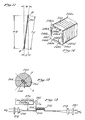
- FIG. 7 illustrates a preferred embodiment of the present invention.
- a birefringent fiber 200 is helically wound around the surface 214 of an acoustic-conducting medium 202, at a constant pitch angle ⁇ such that the fiber is in continuous acoustic contact with the surface 214 through plural turns spaced apart by a pitch distance S.
- the "pitch angle" is the angle of the fiber 200 with respect to a plane normal to the longitudinal axis of the acoustic-conducting medium 202, and, as will be explained below, is equal to the angle of incidence of an acoustic surface wave on the fiber 200.
- the acoustic-conducting medium 202 is a solid rod having a circular cross section having a diameter D.
- the rod is preferably a right circular cylinder (i.e., it has a uniform diameter).
- the rod 202 may be formed of silica glass.
- the fiber 200 is wound on the rod 202 with a small amount of tension applied to the fiber 200 to provide good acoustic contact between the fiber 200 and the rod 202.
- the fiber 200 advantageously can be affixed to the rod 202 by means of a bonding substance such as epoxy glue (not shown), or other means known to the art.
- the tension applied to the fiber 200 is maintained while the glue is curing.
- a bulk wave transducer 204 is attached to one end of the rod 202 and is activated by a source (not shown) of high frequency oscillating voltage to generate a bulk acoustic wave which propagates in the direction indicated by the arrow 206.
- the direction 206 is coincident with the longitudinal axis of the rod 202.
- the bulk transducer 204 can be a PZT (lead zirconium titanate) disk, which typically operates in the frequency range from 1 to 20 MHz; a lithium niobate (LiNbO2) disk, which typically operates in the frequency range from less than 1 MHz to greater than 1 GHz; a zinc oxide disk, which typically operates in the frequency range from 100 MHz to greater than 1 GHz; or other transducers known to the art.
- PZT lead zirconium titanate
- LiNbO2 lithium niobate
- a zinc oxide disk which typically operates in the frequency range from 100 MHz to greater than 1 GHz
- an oscillating electric signal is applied to the piezoelectric transducer 204, it expands and contracts in the direction of the longitudinal axis of the rod 202 to generate the bulk acoustic wave.
- the bulk acoustic wave traveling through the solid rod 202 in the direction indicated by the arrow 206 causes spatially periodic compressions and rarefactions of the rod 202.
- the spatially periodic compressions and rarefactions in the rod cause undulations of the surface of the rod 202. This effect is illustrated in Figure 8, for a short segment of the rod 202.
- the regions of compression and rarefaction are pictorially represented by the phantom lines 208, wherein compression is represented by closely spaced lines 208 in regions 210 and rarefaction is represented by widely spaced lines 208 in regions 212.
- the regions of compression 210 cause expansion of the surfaces 214 of the rod 202, while the regions of rarefaction 212 cause contractions of the surfaces 214 of the rod 202.
- the alternating expansions and contractions of the surface 214 of the rod 202 cause undulations, represented as exaggerated surface waves 216, which travel along the surface 214 of the rod 202 in the direction of the arrow 206.
- the undulations of the surface 214 of the rod 202 cause periodic stresses on the fiber 200 which is wound in acoustic contact with the surface 214 of the rod 202. The stresses affect the fiber in the manner described above in connection with Figure 4.
- a location A represents an arbitrary location on the rod 202 and the fiber 200 which can be considered to be the beginning of one turn of the fiber 200.
- a location B is chosen to be the location on the fiber 200 and the rod 202 one turn further along on the fiber 200 and thus spaced apart from the location A, in the direction indicated by the arrow 206, by the pitch distance S.
- An acoustic wave front traveling from the location A to the location B along the acoustic path provided by the rod 202 will travel the pitch distance S and will irradiate the length of one turn of the fiber 200 between the location A and the location B.
- the length of the optical path, measured along the fiber axis, between the location A and the location B is substantially longer than the acoustic path, measured axially along the rod in the direction of acoustic propagation, between the location A and the location B.
- the wave front will then irradiate a turn of the fiber 200 beginning at location B, followed by subsequent turns of the fiber 200 as the wave front propagates in the direction indicated by the arrow 206.
- each portion of each wave front causes stress on a portion of each of a plurality of turns, thereby providing a cummulative transfer of optical signal energy between the two propagation modes.
- the present invention is particularly advantageous in providing a relatively large amount of acoustic contact between the fiber 200 and the propagating acoustic wave fronts over a relatively short acoustic propagation distance.
- the device can be quite compact.
- the acoustic rod provides an acoustic channel to constrain the acoustic wave fronts to a predetermined acoustic path.
- the rod is formed as a hollow tube, as illustrated in Figure 9 for a rod 222.
- the fiber 200 is wrapped around the hollow rod 222 in the same manner as discussed above in reference to the solid rod 202 of Figure 7.
- the hollow rod 222 has a transducer 224, mounted on one end for generating an acoustic wave.
- the transducer 224 may be of a bulk wave type, such as discussed in reference to Figure 7.
- the hollow rod 222 is quite advantageous in that the bulk acoustic waves generated by the transducer 224 will propagate in the tubular wall of the hollow rod 222, so that the acoustic energy will be more concentrated than if the wave were propagating through the mass of the solid rod 202 ( Figure 7).
- the hollow rod embodiment of Figure 9 causes a larger percentage of the energy of the bulk acoustic waves to be transferred to the surface undulations which stress the fiber 200.
- the transducer 224 can be washer-shaped as illustrated in Figure 9 to match the shape of the hollow cylindrical rod 222, thus concentrating the electrical energy only on piezoelectric material in contact with the end of the rod 222.
- the transducers 204, 224 at the end of the rods 202, 222 may comprise edge-bonded transducers, or other means known to those skilled in the art, for generating surface acoustic waves directly.
- the use of a surface wave transducer is illustrated for the hollow, cylindrical rod 222 in a partial cross-sectional view in Figure 10.
- the transducer 224, attached to one end of the rod 222 may comprise a radially-poled, edge-bonded, surface wave transducer of piezoelectric material.
- the radially-poled transducer 224 generates undulations 238 in the surface 234 of the cylindrical rod 222 which propagate unidirectionally in the direction indicated by the arrow 226. Unlike the surface undulations caused by a bulk acoustic wave, the undulations in the surface 234 of the hollow cylindrical rod 222 in Figure 10 are generated directly by the radially-poled, edge-bonded, transducer 224.
- radially-poled piezoelectric transducers may be constructed from a thin, washer-shaped mass of PZT which is heated and then allowed to cool in the presence of a strong electric field.
- the electric field is symmetrical about the center of the PZT material.
- the PZT material is polarized in the direction of the field, i.e., radially.
- an oscillating electric field (not shown) is applied to the PZT material, the material expands and contracts along its radii, thus periodically increasing and decreasing its diameter and circumference.
- the outer circumference (i.e., the edge) of the PZT transducer 224 is bonded to the outer circumference of the rod 222.
- the expansion and contraction of the transducer 224 induces undulations in the surface of the rod 222 which propagate in the direction indicated by arrow 226, as described above.
- an acoustic absorbing material such as a black wax
- an acoustic absorbing material such as a black wax
- Figure 11 illustrates one turn of the fiber 200 of Figure 7 with the fiber unwrapped from the rod 202 to show the trigonometric relationships between the dimensions.
- the locations A and B in Figure 11 generally correspond to the locations A and B in Figure 7 and represent the beginning and end of a one-turn length of the fiber 200.
- each turn of the fiber advances down the rod 202 by the distance S which is referred to as the "pitch distance" of the turn.
- the length of fiber in each turn L f ( Figure 11) is determined by the pitch distance S and the diameter D of the rod 202.
- the length L f forms the hypotenuse of a right triangle having sides of lengths S and ⁇ D, respectively.
- the length L f can be determined by the following equation:
- the fiber 200 forms an angle with a plane normal to the direction of propagation 206 of the acoustic wave, referred to herein as the "pitch angle" ⁇ .
- the acoustic wave length can be determined from the following equation:
- the acoustic frequency for proper phase matching can therefore be determined from the foregoing equation as follows: where f a is the acoustic frequency; and V a is the velocity of the acoustic wave on the surface of the rod 202.
- the velocity of the acoustic wave may be approximately 6,000 meters per second; the diameter D of the rod 202 may be 12.7 mm (i.e., ⁇ 0.5 inches); the pitch distance or spacing S may be 1.0 mm; and the beat length L may be 1.65 mm.
- the pitch S can be as small as 0.1 mm by winding the turns such that the cladding of adjacent turns is in contact.
- Substituting 0.1 mm for the value of S in equation 10 yields a theoretical maximum frequency of 1450 MHz for the embodiment described, subject to limitations of the acoustic bandwidth of the acoustic transducer and the rod.
- the frequency theoretically can be increased further by increasing the diameter of the rod 202 or by substituting a fiber 200 with a smaller diameter cladding. In any case, this device is capable of providing a frequency response significantly higher than heretofore possible.
- the structural configuration of the present invention permits each wave front to irradiate long lengths of optical fiber over a relatively short acoustic propagation distance and thus efficiently utilizes the acoustic energy.
- the 145 MHz device described above can have 10 turns of fiber wrapped on a 10.0 mm length of the 12.7 mm diameter rod 202. Simple calculations show that approximately 399 mm of fiber can be wrapped on the rod 202 in this length.
- each acoustic wave front traveling a distance of 10.0 mm can irradiate approximately 399 mm of fiber.
- the angle of incidence of the acoustic wave on the fiber 200 can be varied by varying the spacing S between turns of the fiber.
- different portions of the fiber on the rod 202 can be made responsive to different frequencies.
- the pitch of the winding may be varied over a number of turns so that a sufficient length of fiber has the beat length substantially matched with each of the acoustic wave lengths in the range of the frequency shifter.
- each turn of fiber is approximately 24 beat lengths long (i.e., ⁇ X 12.7 mm ⁇ 1.65 mm).
- the fiber 200 in Figure 7 be a single mode birefringent fiber having two orthogonal polarization modes such as described above in connection with Figure 1.
- This fiber has an elliptical core which is placed on the surface of the rod 202 with the principal axes of the core at an angle of approximately 45° with respect to the surface of the rod 202.
- Another type of fiber which is particularly advantageous for use in the present invention is a D-shaped cross section, as illustrated in Figure 12. This D-shaped fiber is available from Andrew Corporation, 10500 W. 153rd Street, Orland Park, Illinois 60462.
- the cladding 262 of the D-shaped fiber 260 is not circular, but has a flat surface 264 on one side thereof.
- the fiber 260 also has an elliptical core 266 which is oriented in the cladding 242 with its major axis, X, at an angle ⁇ with respect to the flat surface 264.
- the angle ⁇ is substantially equal to 45°.
- D-shaped fiber A description of a D-shaped fiber can be found in R.B. Dyott, et al , "SELF-LOCATING ELLIPTICALLY CORED FIBRE WITH AN ACCESSIBLE GUIDING REGION,” ELECTRONICS LETTERS , Vol. 18, No. 22, October 28, 1982, pp. 980-981.
- the above-described frequency shifter may be utilized to provide single side band modulated light.
- an input light wave, W i is first passed through a modal filter, e.g., a polarizer 272, to ensure that the light is linearly polarized along one of the principal axes of birefringence of the fiber 200.
- a lens 274 is used to focus light from the polarizer 272 for introduction into the end of the fiber 200.
- the fiber 200 is wound on the rod 202 as described in connection with Figure 7.
- a polarization controller 276 at the input end of the fiber 200 to permit final adjustment of the polarization to compensate for any such perturbation of the axis of birefringence.
- a polarization controller which is suitable for use with the present invention, is described in an article by R. Ulrich and M. Johnson entitled “Single Mode Fiber Optical Polarization Rotator", Applied Optics , Vol. 8, No. 11 (1 June 1979), pages 1857-1861.
- the transducer 204 on the end of the rod 202 is driven by a source 282 of an oscillating electric signal of frequency f a to produce acoustic waves in the rod 202.
- the acoustic waves cause it to be at least partially coupled from the mode to which it was input, to the orthogonal mode, and such coupled light is shifted in frequency by an amount equal to the acoustic frequency, f a , in accordance with the discussion in reference to Figures 3-11.
- the direction of frequency shift i.e., upshift or downshift
- the light exiting the fiber 200 will contain frequency shifted light in one mode, and, if the input light was not 100% coupled, non-shifted light in the other mode.
- the light is then passed through a lens 278, for collimation purposes, and then through a modal filter, e.g., polarizer 280, oriented to block the non-shifted light in the original input mode, so that only the shifted light is passed by the polarizer 280 to form an output wave, W o .
- polarizer 280 oriented to block the non-shifted light in the original input mode, so that only the shifted light is passed by the polarizer 280 to form an output wave, W o .
- Figure 14 illustrates the fiber 200 wrapped on a rod 242 having a generally square cross section so as to provide four flat surfaces 244a, 244b, 244c, 244d.
- the rod 242 will advantageously have curved corners 246a, 246b, 246c, 246d, in order to avoid sharp bends in the fiber 200 when wrapped on the rod 242.
- the radius of curvature of the corners 246a-d is chosen such that light in the fiber 200 wrapped on the rod 242 will remain well-guided around the corners.
- the rectangular cross section for the rod 242 in Figure 14 has the particular advantage that simple edge-bonded transducers 248a, 248b, 248c, 248d may be utilized to generate surface acoustic waves on each of the flat surfaces 244a-d. Furthermore, the transducers 248a-d can be driven individually at different frequencies or amplitudes to vary the amount of energy transferred between the modes and the magnitude of the frequency shift.
- the pitch angles of the windings on each of the surfaces may be the same or they may be different; however, in either case the pitch angles should preferably be selected to match the desired acoustic frequencies.
- the present invention can also be used as an acoustic detector, responsive to a selected frequency or range of frequencies, by using the described embodiments without the transducers.
- the rod or other acoustic conducting medium is placed in the path of an acoustic wave and oriented in the direction of the acoustic propagation.
- the frequency of a light signal propagating through the optical fiber wound on the rod will be frequency shifted by an acoustic wave of proper frequency.
- the frequency shifter of the present invention can be wound with varying pitch to be responsive to a range of acoustic frequencies.
- the acoustic detector of the present invention can be used as an acoustic direction finder.
- a single acoustic detector will have its maximum response, i.e., the greatest amount of energy at the shifted frequency, when oriented in the direction of propagation of the acoustic wave.
- a plurality of acoustic detectors placed in orthogonal orientations can also be used as direction finders by comparing the relative magnitudes of the responses of each of the detectors and calculating the acoustic propagation direction which corresponds to the magnitudes.
- nonbirefringent fiber may alternatively be utilized in the present invention.
- the fiber should he selected to support two modes, namely, the first and second order modes for the particular wavelength of light utilized.
- frequency shifted light will be coupled between the two modes, i.e., from the first order mode to the second order mode.
- Such coupling is due to perturbation of the modes caused by the acoustic stresses as they travel down the fiber.
- a more detailed explanation of the theory for such modal coupling is discussed in European patent application no. 84307920.3, publication no. 0143583, entitled “Fiber Optic Modal Coupler,” and in an article, "Two-Mode Fiber Modal Coupler,” R.C. Youngquist, et al , OPTICS LETTERS , Vol. 9, No. 5, May, 1984, pp. 177-179, which are hereby incorporated herein by reference.
- a nonbirefringent fiber may thus be alternatively utilized in a single side band modulator using the present invention.
- the input light should be launched exclusively in the second order mode of the fiber, and a modal filter, e.g., mode stripper (not shown), should be placed at the output end of the device to suppress the second order mode such that only frequency shifted light coupled to the first order mode is output from the device.
- a modal filter e.g., mode stripper (not shown)
Landscapes
- Physics & Mathematics (AREA)
- Nonlinear Science (AREA)
- General Physics & Mathematics (AREA)
- Optics & Photonics (AREA)
- Mechanical Light Control Or Optical Switches (AREA)
- Optical Integrated Circuits (AREA)
- Light Guides In General And Applications Therefor (AREA)
- Liquid Crystal (AREA)
- Electrochromic Elements, Electrophoresis, Or Variable Reflection Or Absorption Elements (AREA)
- Polarising Elements (AREA)
- Transducers For Ultrasonic Waves (AREA)
Claims (18)
- Faseroptischer Frequenzschieber, der ein akustisch leitendes Medium (202, 222, 242) zur Fortpflanzung einer akustischen Welle aufweist, der weiterhin eine optische Faser (200) aufweist, die erste und zweite Moden hat, die Licht entlang einer zentralen Achse mit einer ersten und einer zweiten Geschwindigkeit fortpflanzen, wobei die Faser in akustischem Kontakt mit dem Medium steht, dadurch gekennzeichnet, daß die Faser (200) um das akustisch leitende Medium (202) herum gewunden ist, um eine Vielzahl von Windungen der Faser zu erzeugen, wobei wenigstens ein Teil der Faser in jeder Windung in akustischem Kontakt mit dem Medium angeordnet ist, wobei jedes Teil der Faser derart angeordnet ist, daß die zentrale Achse der Faser (206) in jedem Teil unter einem Einfallswinkel (ϑ) steht, der größer als 0o und kleiner als 90o relativ zur Fortpflanzungsrichtung der akustischen Welle ist, wenn dar Schieber in Betrieb ist.
- Faseroptischer Frequenzschieber nach Anspruch 1, dadurch gekennzeichnet, daß die Faser eine doppelbrechende Einzel-Moden-Faser ist.
- Faseroptischer Frequenzschieber nach Anspruch 2, dadurch gekennzeichnet, daß die Faser einen Kern (266) hat, der von einer Umhüllung (262) umgeben ist, die ein flaches Teil (264) hat, das mit einem vorgegebenen Winkel in Bezug auf die Achsen der Doppelbrechung der Faser angeordnet ist, wobei das flache Teil in akustischem Kontakt mit dem Medium steht.
- Faseroptischer Frequenzschieber nach einem der Ansprüche 1 bis 3, dadurch gekennzeichnet, daß das Medium einen Draht (202) aufweist, wobei die Faser um den Draht herum gewunden ist.
- Faseroptischer Frequenzschieber nach Anspruch 4, dadurch gekennzeichnet, daß die Faser in im wesentlichen durchgehendem akustischem Kontakt mit der Oberfläche des Drahtes über die Vielzahl der Windungen steht.
- Faseroptischer Frequenzschieber nach Anspruch 4 oder 5, dadurch gekennzeichnet, daß der Draht zylindrisch ist.
- Faseroptischer Frequenzschieber nach einem der Ansprüche 4 bis 6, dadurch gekennzeichnet, daß die Faser schraubenförmig um den Draht gewunden ist.
- Faseroptischer Frequenzschieber nach Anspruch 7, dadurch gekennzeichnet, daß der Abstand zwischen den Windungen konstant ist.
- Faseroptischer Frequenzschieber nach einem der Ansprüche 4 bis 7, dadurch gekennzeichnet, daß der Windungswinkel mindestens eines Teils der Faser auf dem Draht verschieden von dem Windungswinkel mindestens eines anderen Teils der Faser ist.
- Faseroptischer Frequenzschieber nach einem der Ansprüche 4 bis 9, dadurch gekennzeichnet, daß der Draht massiv ist.
- Faseroptischer Frequenzschieber nach einem der vorhergehenden Ansprüche, dadurch gekennzeichnet, daß er einen akustischen Wandler (204, 224, 248a - 248d) zur Erzeugung der akustischen Welle aufweist.
- Verfahren zum Verschieben der Frequenz eines optischen Signals mit folgenden Schritten:- das optische Signal wird bei einer ersten Frequenz durch eine Vielzahl von Windungen einer optischen Faser (200) fortgepflanzt, die eine zentrale Achse (206) und zwei Fortpflanzungsmoden hat, wobei die Faser mit mindestens einem Teil jeder Windung in akustischem Kontakt mit einem akustisch leitenden Medium (202, 222, 242) gewunden ist;- ein akustisches Signal wird entlang des akustisch leitenden Mediums geleitet, um einen Kontakt zu den Teilen der Windungen herzustellen, so daß der Einfallswinkel der Wellenfronten des akustischen Signals in Bezug auf die zentrale Achse der Faser größer als 0o und kleiner als 90o ist, wobei das akustische Signal die Faser dehnt, um zu bewirken, daß optische Energie des optischen Signals, das sich in einer der Moden fortpflanzt, auf die andere Mode übertragen und in der Frequenz zu einer zweiten Frequenz verschoben wird.
- Verfahren nach Anspruch 12, dadurch gekennzeichnet, daß die Faser eine Schwebungslänge für ein Lichtsignal hat, das sich darin fortpflanzt, und daß die Wellenlänge der akustischen Welle im wesentlichen gleich der Schwebungslänge der Faser ist, multipliziert mit dem Sinus des Einfallswinkels von mindestens einem der Teile.
- Verfahren nach Anspruch 12, dadurch gekennzeichnet, daß die Frequenzverschiebung des optischen Signals im wesentlichen gleich der Frequenz des akustischen Signals ist.
- Verfahren nach einem der Ansprüche 12 bis 14, dadurch gekennzeichnet, daß es auf einen faseroptischen Frequenzschieber nach einem der Ansprüche 2 bis 11 angewendet wird.
- Verwendung eines faseroptischen Frequenzschiebers nach einem der Ansprüche 1 bis 11 für die Umwandlung von Licht einer Frequenz in Licht einer anderen Frequenz.
- Verwendung eines faseroptischen Frequenzschiebers nach Anspruch 1 als akustischen Detektor für eine ausgewählte Frequenz oder einen Frequenzbereich eines akustischen Signals.
- Verwendung eines faseroptischen Frequenzschiebers nach Anspruch 1 als Richtungsfinder für ein akustisches Signal.
Priority Applications (1)
| Application Number | Priority Date | Filing Date | Title |
|---|---|---|---|
| AT86300754T ATE74448T1 (de) | 1985-02-08 | 1986-02-05 | Optische faser mit mehreren windungen als akustooptischer frequenzschieber. |
Applications Claiming Priority (2)
| Application Number | Priority Date | Filing Date | Title |
|---|---|---|---|
| US06/699,666 US4735484A (en) | 1985-02-08 | 1985-02-08 | Acousto-optic frequency shifter utilizing multi-turn optical fiber |
| US699666 | 1991-05-14 |
Publications (3)
| Publication Number | Publication Date |
|---|---|
| EP0190923A2 EP0190923A2 (de) | 1986-08-13 |
| EP0190923A3 EP0190923A3 (en) | 1988-06-01 |
| EP0190923B1 true EP0190923B1 (de) | 1992-04-01 |
Family
ID=24810360
Family Applications (1)
| Application Number | Title | Priority Date | Filing Date |
|---|---|---|---|
| EP86300754A Expired - Lifetime EP0190923B1 (de) | 1985-02-08 | 1986-02-05 | Optische Faser mit mehreren Windungen als akustooptischer Frequenzschieber |
Country Status (9)
| Country | Link |
|---|---|
| US (1) | US4735484A (de) |
| EP (1) | EP0190923B1 (de) |
| JP (1) | JPS61200526A (de) |
| KR (1) | KR940001910B1 (de) |
| AT (1) | ATE74448T1 (de) |
| AU (1) | AU5275586A (de) |
| CA (1) | CA1267310A (de) |
| DE (1) | DE3684624D1 (de) |
| NO (1) | NO860433L (de) |
Families Citing this family (13)
| Publication number | Priority date | Publication date | Assignee | Title |
|---|---|---|---|---|
| US4828350A (en) * | 1986-01-17 | 1989-05-09 | The Board Of Trustees Of The Leland Stanford Junior University | Fiber optic mode selector |
| US4832437A (en) * | 1986-01-17 | 1989-05-23 | The Board Of Trustees Of The Leland Stanford Junior University | Fiber optic inter-mode coupling single side band frequency shifter |
| US5022732A (en) * | 1986-01-17 | 1991-06-11 | The Board Of Trustees Of The Leland Stanford Junior University | Fiber optic intermode coupling single sideband frequency shifter |
| US4872738A (en) * | 1986-02-18 | 1989-10-10 | The Board Of Trustees Of The Leland Stanford Junior University | Acousto-optic fiber-optic frequency shifter using periodic contact with a surface acoustic wave |
| GB8622609D0 (en) * | 1986-09-19 | 1986-10-22 | Rogers A J | Optical fibres |
| US4914665A (en) * | 1987-01-20 | 1990-04-03 | Hewlett-Packard Company | Broadband-tunable external fiber-cavity laser |
| US4915468A (en) * | 1987-02-20 | 1990-04-10 | The Board Of Trustees Of The Leland Stanford Junior University | Apparatus using two-mode optical waveguide with non-circular core |
| GB8706272D0 (en) * | 1987-03-17 | 1987-04-23 | Sieger Ltd | Fibre optic telemetry |
| US5101449A (en) * | 1990-06-05 | 1992-03-31 | Matsushita Electric Industrial Co., Ltd. | Optical phase modulator with asymmetric piezoelectric vibrator |
| US5329354A (en) * | 1991-04-24 | 1994-07-12 | Matsushita Electric Industrial Co., Ltd. | Alignment apparatus for use in exposure system for optically transferring pattern onto object |
| RU2176411C1 (ru) * | 2000-03-31 | 2001-11-27 | Павлов Борис Сергеевич | Оптико-акустический частотный фильтр |
| JP2005136467A (ja) * | 2003-10-28 | 2005-05-26 | Tdk Corp | 圧電共振器およびそれを用いた電子部品 |
| WO2016097256A1 (en) * | 2014-12-18 | 2016-06-23 | Ge Healthcare Bio-Sciences Ab | Optical fiber arrangement for a system for measuring the light absorption or determining the concentration of a substance |
Family Cites Families (14)
| Publication number | Priority date | Publication date | Assignee | Title |
|---|---|---|---|---|
| US3912363A (en) * | 1974-01-29 | 1975-10-14 | Rca Corp | Optical fiber to planar waveguide coupler |
| JPS5241541A (en) * | 1975-09-29 | 1977-03-31 | Nippon Telegr & Teleph Corp <Ntt> | Input-output equipment for optical fibers |
| US4097118A (en) * | 1975-10-30 | 1978-06-27 | Rca Corporation | Optical waveguide coupler employing deformed shape fiber-optic core coupling portion |
| US4018506A (en) * | 1975-11-12 | 1977-04-19 | Rca Corporation | Fiber-optic to planar-waveguide optical coupler |
| JPS5267345A (en) * | 1975-12-01 | 1977-06-03 | Nippon Telegr & Teleph Corp <Ntt> | Mixing device for optical fiber modes |
| US4086484A (en) * | 1976-07-14 | 1978-04-25 | International Telephone And Telegraph Corporation | Optical amplitude modulation modulator |
| US4319186A (en) * | 1978-05-05 | 1982-03-09 | National Research Development Corporation | Signal sensors |
| US4236786A (en) * | 1978-12-13 | 1980-12-02 | Corning Glass Works | Method of effecting coupling of selected modes in an optical waveguide |
| DE3006102A1 (de) * | 1979-02-19 | 1980-08-28 | Ricoh Kk | Optische steuereinrichtung |
| JPS55155324A (en) * | 1979-05-23 | 1980-12-03 | Ricoh Co Ltd | Optical fiber device |
| US4268116A (en) * | 1979-10-26 | 1981-05-19 | Optelecom Incorporated | Method and apparatus for radiant energy modulation in optical fibers |
| US4386822A (en) * | 1980-10-10 | 1983-06-07 | The Leland Stanford Junior University | Polarizer and method |
| US4588296A (en) * | 1981-10-07 | 1986-05-13 | Mcdonnell Douglas Corporation | Compact optical gyro |
| GB2125572B (en) * | 1982-08-03 | 1985-12-24 | Standard Telephones Cables Ltd | Optical fibre sensors |
-
1985
- 1985-02-08 US US06/699,666 patent/US4735484A/en not_active Expired - Fee Related
-
1986
- 1986-01-28 AU AU52755/86A patent/AU5275586A/en not_active Abandoned
- 1986-02-05 AT AT86300754T patent/ATE74448T1/de not_active IP Right Cessation
- 1986-02-05 DE DE8686300754T patent/DE3684624D1/de not_active Expired - Lifetime
- 1986-02-05 EP EP86300754A patent/EP0190923B1/de not_active Expired - Lifetime
- 1986-02-06 JP JP61025650A patent/JPS61200526A/ja active Pending
- 1986-02-07 NO NO860433A patent/NO860433L/no unknown
- 1986-02-07 CA CA000501343A patent/CA1267310A/en not_active Expired - Lifetime
- 1986-02-07 KR KR1019860000852A patent/KR940001910B1/ko not_active Expired - Fee Related
Also Published As
| Publication number | Publication date |
|---|---|
| DE3684624D1 (de) | 1992-05-07 |
| NO860433L (no) | 1986-08-11 |
| ATE74448T1 (de) | 1992-04-15 |
| KR860006718A (ko) | 1986-09-13 |
| EP0190923A3 (en) | 1988-06-01 |
| AU5275586A (en) | 1986-08-14 |
| CA1267310A (en) | 1990-04-03 |
| KR940001910B1 (ko) | 1994-03-11 |
| EP0190923A2 (de) | 1986-08-13 |
| JPS61200526A (ja) | 1986-09-05 |
| US4735484A (en) | 1988-04-05 |
Similar Documents
| Publication | Publication Date | Title |
|---|---|---|
| US4832437A (en) | Fiber optic inter-mode coupling single side band frequency shifter | |
| EP0144190B1 (de) | Einseitenband-Modulator mit einer optischen Monomode-Faser | |
| US5022732A (en) | Fiber optic intermode coupling single sideband frequency shifter | |
| US4781425A (en) | Fiber optic apparatus and method for spectrum analysis and filtering | |
| KR950002418B1 (ko) | 광학 섬유 상호 모우드 결합 단일 측파대 주파수 전이기 | |
| EP0190923B1 (de) | Optische Faser mit mehreren Windungen als akustooptischer Frequenzschieber | |
| US4735485A (en) | Acousto-optic frequency shifter using optical fiber and method of manufacturing same | |
| US4793676A (en) | Optical fiber acousto-optic amplitude modulator | |
| US4792207A (en) | Single mode fiber optic single sideband modulator and method of frequency shifting using same | |
| US4725124A (en) | Fiber optic microbend phase shifter and modulator | |
| US4666255A (en) | Method and apparatus for acousto-optically shifting the frequency of a light signal propagating in a single-mode fiber | |
| EP0233749B1 (de) | Akusto-optischer, faser-optischer Frequenzumsetzer, der auf periodischem Kontakt mit einer akustischen Oberflächenwelle beruht | |
| EP0230369B1 (de) | Faseroptischer modengekoppelter Einseitenbandfrequenzschieber | |
| Blake et al. | All-fiber acousto-optic frequency shifter using two-mode fiber | |
| Youngquist et al. | All-fibre components using periodic coupling | |
| EP0183420A2 (de) | Akustooptischer Amplitudenmodulator mit einer optischen Faser | |
| EP0192887A2 (de) | Phasenmodulator mit einer optischen Faser | |
| CA1292089C (en) | Apparatus using two-mode optical waveguide with non- circular core | |
| Blotekjaer et al. | Acousto-optic interaction in two-mode optical fibers | |
| Yu | Collinear acousto-optic interactions in optical fibers using laser generated flexural acoustic waves | |
| JPS61153618A (ja) | フアイバ光学振幅変調器 |
Legal Events
| Date | Code | Title | Description |
|---|---|---|---|
| PUAI | Public reference made under article 153(3) epc to a published international application that has entered the european phase |
Free format text: ORIGINAL CODE: 0009012 |
|
| AK | Designated contracting states |
Kind code of ref document: A2 Designated state(s): AT BE CH DE FR GB IT LI LU NL SE |
|
| PUAL | Search report despatched |
Free format text: ORIGINAL CODE: 0009013 |
|
| AK | Designated contracting states |
Kind code of ref document: A3 Designated state(s): AT BE CH DE FR GB IT LI LU NL SE |
|
| 17P | Request for examination filed |
Effective date: 19881121 |
|
| 17Q | First examination report despatched |
Effective date: 19910319 |
|
| GRAA | (expected) grant |
Free format text: ORIGINAL CODE: 0009210 |
|
| ITF | It: translation for a ep patent filed | ||
| AK | Designated contracting states |
Kind code of ref document: B1 Designated state(s): AT BE CH DE FR GB IT LI LU NL SE |
|
| PG25 | Lapsed in a contracting state [announced via postgrant information from national office to epo] |
Ref country code: SE Effective date: 19920401 Ref country code: NL Effective date: 19920401 Ref country code: LI Effective date: 19920401 Ref country code: CH Effective date: 19920401 Ref country code: BE Effective date: 19920401 Ref country code: AT Effective date: 19920401 |
|
| REF | Corresponds to: |
Ref document number: 74448 Country of ref document: AT Date of ref document: 19920415 Kind code of ref document: T |
|
| REF | Corresponds to: |
Ref document number: 3684624 Country of ref document: DE Date of ref document: 19920507 |
|
| REG | Reference to a national code |
Ref country code: CH Ref legal event code: PL |
|
| ET | Fr: translation filed | ||
| NLV1 | Nl: lapsed or annulled due to failure to fulfill the requirements of art. 29p and 29m of the patents act | ||
| PGFP | Annual fee paid to national office [announced via postgrant information from national office to epo] |
Ref country code: LU Payment date: 19930114 Year of fee payment: 8 |
|
| PLBE | No opposition filed within time limit |
Free format text: ORIGINAL CODE: 0009261 |
|
| STAA | Information on the status of an ep patent application or granted ep patent |
Free format text: STATUS: NO OPPOSITION FILED WITHIN TIME LIMIT |
|
| ITTA | It: last paid annual fee | ||
| 26N | No opposition filed | ||
| EPTA | Lu: last paid annual fee | ||
| PG25 | Lapsed in a contracting state [announced via postgrant information from national office to epo] |
Ref country code: LU Free format text: LAPSE BECAUSE OF NON-PAYMENT OF DUE FEES Effective date: 19940205 |
|
| PGFP | Annual fee paid to national office [announced via postgrant information from national office to epo] |
Ref country code: DE Payment date: 19940331 Year of fee payment: 9 |
|
| PGFP | Annual fee paid to national office [announced via postgrant information from national office to epo] |
Ref country code: FR Payment date: 19941216 Year of fee payment: 10 |
|
| PGFP | Annual fee paid to national office [announced via postgrant information from national office to epo] |
Ref country code: GB Payment date: 19950103 Year of fee payment: 10 |
|
| PG25 | Lapsed in a contracting state [announced via postgrant information from national office to epo] |
Ref country code: DE Effective date: 19951101 |
|
| PG25 | Lapsed in a contracting state [announced via postgrant information from national office to epo] |
Ref country code: GB Effective date: 19960205 |
|
| GBPC | Gb: european patent ceased through non-payment of renewal fee |
Effective date: 19960205 |
|
| PG25 | Lapsed in a contracting state [announced via postgrant information from national office to epo] |
Ref country code: FR Effective date: 19961031 |
|
| REG | Reference to a national code |
Ref country code: FR Ref legal event code: ST |
|
| PG25 | Lapsed in a contracting state [announced via postgrant information from national office to epo] |
Ref country code: IT Free format text: LAPSE BECAUSE OF NON-PAYMENT OF DUE FEES;WARNING: LAPSES OF ITALIAN PATENTS WITH EFFECTIVE DATE BEFORE 2007 MAY HAVE OCCURRED AT ANY TIME BEFORE 2007. THE CORRECT EFFECTIVE DATE MAY BE DIFFERENT FROM THE ONE RECORDED. Effective date: 20050205 |