EP0190933A2 - Ersetzen von Rohren - Google Patents
Ersetzen von Rohren Download PDFInfo
- Publication number
- EP0190933A2 EP0190933A2 EP86300800A EP86300800A EP0190933A2 EP 0190933 A2 EP0190933 A2 EP 0190933A2 EP 86300800 A EP86300800 A EP 86300800A EP 86300800 A EP86300800 A EP 86300800A EP 0190933 A2 EP0190933 A2 EP 0190933A2
- Authority
- EP
- European Patent Office
- Prior art keywords
- pipe
- existing pipe
- rear portion
- front portion
- existing
- Prior art date
- Legal status (The legal status is an assumption and is not a legal conclusion. Google has not performed a legal analysis and makes no representation as to the accuracy of the status listed.)
- Withdrawn
Links
Images

Classifications
-
- E—FIXED CONSTRUCTIONS
- E21—EARTH OR ROCK DRILLING; MINING
- E21B—EARTH OR ROCK DRILLING; OBTAINING OIL, GAS, WATER, SOLUBLE OR MELTABLE MATERIALS OR A SLURRY OF MINERALS FROM WELLS
- E21B7/00—Special methods or apparatus for drilling
- E21B7/28—Enlarging drilled holes, e.g. by counterboring
- E21B7/30—Enlarging drilled holes, e.g. by counterboring without earth removal
-
- F—MECHANICAL ENGINEERING; LIGHTING; HEATING; WEAPONS; BLASTING
- F16—ENGINEERING ELEMENTS AND UNITS; GENERAL MEASURES FOR PRODUCING AND MAINTAINING EFFECTIVE FUNCTIONING OF MACHINES OR INSTALLATIONS; THERMAL INSULATION IN GENERAL
- F16L—PIPES; JOINTS OR FITTINGS FOR PIPES; SUPPORTS FOR PIPES, CABLES OR PROTECTIVE TUBING; MEANS FOR THERMAL INSULATION IN GENERAL
- F16L55/00—Devices or appurtenances for use in, or in connection with, pipes or pipe systems
- F16L55/16—Devices for covering leaks in pipes or hoses, e.g. hose-menders
- F16L55/162—Devices for covering leaks in pipes or hoses, e.g. hose-menders from inside the pipe
- F16L55/165—Devices for covering leaks in pipes or hoses, e.g. hose-menders from inside the pipe a pipe or flexible liner being inserted in the damaged section
- F16L55/1658—Devices for covering leaks in pipes or hoses, e.g. hose-menders from inside the pipe a pipe or flexible liner being inserted in the damaged section the old pipe being ruptured prior to insertion of a new pipe
Definitions
- This invention relates to a method and apparatus for replacing underground pipes, in particular non-pressurised pipes such as water or sewage pipes.
- European Patent Specification No 53480 describes a device which is guided by a cable through an existing pipe and which has radially extending blades on the front portion of the device, these blades serving to engage the inside wall of the existing pipe.
- the device includes a pneumatically operated hammer which is enclosed within an external housing of the device and has surfaces which act percussively on corresponding surfaces of an internal bore within the device to cause the blades to fracture the existing pipe.
- the device includes means to attach a new pipe or liner to the rear of the device so that as the existing pipe is broken, the new pipe is towed along behind the device.
- the cable is attached to the front portion of the device and serves to guide the device axially through the existing pipe.
- pneumatic mechanism means that the device cannot be operated successfully when it is submerged in water or sewage, since the pneumatic mechanism will be choked by any ingress of water or sewage.
- a device for replacing an existing pipe with a new pipe comprising a front portion for engaging the internal walls of the existing pipe, a rear portion having means for attaching thereto a new pipe, said front and rear portions being without any structural connection therebetween but, at least in use, being held in mutual engagement by means of at least one flexible elongate member through which a force is applied to hold the rear portion in engagement with the front portion, the device including means for vibrating the front portion relative to the rear portion at a frequency sufficient to shatter the existing pipe.
- front and rear portions What is meant by there being no structural connection between the front and rear portions is that if the front portion were to be pulled forwards by a force applied to the front portion, the rear portion would stay where it was.
- the front and rear portions are held in mutual engagement when the device is being operated, by applying a forward force to the rear portion.
- the device is driven through the existing pipe by vibrating the front portion of the device relative to the rear portion whilst maintaining the front and rear portions in engagement by applying a forward force to the rear portion.
- This force is applied through the or each flexible elongate element for example a cable attached to the rear portion, or alternatively passing around the back of the rear portion.
- the device shatters the existing pipe by vibrating the front portion relative to the rear portion at a frequency sufficient to cause shock waves in the existing pipe. Because the existing pipe is shattered by vibration rather than fractured by a percussive force transmitted to the pipe by radially extending blades, the disturbance to the surrounding ground is minimised.
- the new pipe may be a replacement pipe of the same diameter as or a larger diameter than the existing pipe, or may be an outer sleeve for replacement pipe.
- the means to vibrate the front portion relative to the rear portion comprises an hydraulically operated hammer located within the rear portion.
- the hammer has a short stroke and operates at a high strike rate.
- the strike rate is at least 1,500 strikes per minute, with the most preferred rate being 2,400 strikes per minute.
- the device uses an efficient hydraulic mechanism, it is of dimensions and weight suitable for handling by two operatives, and is small enough to be operated from manhole to manhole with a minimum of excavation.
- the device is operable completely submerged under water or sewage, since the hydraulic mechanism is more resistant to the effects of water or sewage entering the device.
- the device is moved through the pipe, shattering it and towing behind a new pipe. Subsequent lengths of new pipe are joined on to the free end of the previous length of pipe as necessary.
- a method of replacing an existing pipe with a new pipe comprising inserting within the existing pipe a device having a front portion for engaging the internal walls of the existing pipe, a rear portion having means for attaching thereto a new pipe, and means for vibrating the front portion relative to the rear portion at a frequency sufficient to shatter the existing pipe, said front and rear portions being without any structural connection therebetween, keeping said front and rear portions in mutual engagement by applying a force through at least one flexible elongate member to the rear portion of the device which tends to hold the rear portion in engagement with the front portion, and simultaneously vibrating the front portion relative to the rear portion whereby the device is driven along and shatters the existing pipe.
- the device preferably includes at the front portion one inlet hose and one outlet hose carrying hydraulic fluid to and from the hydraulically operated hammer.
- the device preferably has attached to the front portion a rigid tubular member through which the inlet and outlet hydraulic hoses pass, the rigid tubular member serving to protect the hydraulic hoses from damage caused by collapse of the existing pipe ahead of the device.
- the device may be adapted so as to prevent ingress of soil, water, sewage and the like, so minimising the risk of failure whilst the device is working submerged.
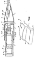
- a device in accordance with the present invention comprises a front portion 1, and a rear portion 2.
- the front portion 1 has an outer casing 6 of conical shape, typically of steel, which, in use, engages the internal walls of the existing pipe.
- closure collets 7 At the forwardmost end of the front casing 6 there is a set of closure collets 7 which effectively seal off the inside of the device from ingress of soil, water, sewage or other substances whilst allowing two hydraulic hoses 8, 8A, one inlet and one outlet, and two cables 9, 9A, one close to each side of the inner surface of the casing 6, to be fixed into position. This enclosed structure allows the device to be used completely submerged.
- the front portion 1 has either formed integrally with, or arranged for a locking taper fit within member 11, a shaft 10 which tapers inwardly towards its forwardmost end.
- the member 11 has four holes drilled through it, two holes accommodating the hydraulic inlet and outlet hoses 8, 8A and two holes accommodating the cables 9, 9A.
- the shaft 10, in the embodiment shown in Figure 1, is tapered to a locking fit within a hole in the centre of the member 11. In operation, the shaft 10 remains almost motionless serving to convert the translational energy provided by the hydraulic mechanism within the rear portion 2 into I vibrational energy of the front portion 1.
- the rear portion 2 comprises a casing 14 of square cross-section and typically of aluminium within which is housed a hydraulically operated hammer 13.
- the details of the workings of the hydraulic hammer are not discussed here 5 in detail as they are known to one skilled in this particular field.
- the rearmost end of the shaft 10 is kept in engagement with the head of the hammer by applying a force through the two cables 9, 9A.
- a number of keep plates 15 having tightening screws are positioned along opposite sides of the casing 14 which fix the ends of the cables 9, 9A rigidly against the sides of the casing 14, thus allowing the hammer head to be kept in engagement with the rearmost end of the shaft 10 by applying tension to the cables 9, 9A.
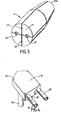
- a pair of driving dogs 5 have the general configuration shown in Figure 3, consisting of a block having a lower surface 16 which is bolted through holes 20 against a face of the casing 14 such that the overhang 16A fits inside the hollow casing 14 and an outer portion 17 which connects two surfaces 18 and 19.
- a length of replacement pipe 4 is secured onto the device by cutting two windows in opposite sides of the pipe 4, sliding the pipe 4 onto the device, dropping the dogs through the window and bolting them tightly against casing 14 such that the surfaces 18 and 19 engage the cut edges of the windows in the pipe 4, thus allowing a section of replacement pipe to be pulled along behind the device.
- These dogs 5 serve to take the strain on each corner of the casing 14.
- this section of replacement pipe 4 which may be of any desired length, is left in position and subsequent lengths of replacement pipe are butt-fused to the free end of the fixed section of pipe.
- the closure collets 7 are made from four separate square bars, which are clamped together and drilled with two large holes 22 to accommodate the hydraulic hoses 8, 8A and two smaller holes 23 to accommodate the cables 9, 9A, the holes being drilled 5 in the inner edges of the bars.
- the bars are then machined to have a circular outer surface which may then be further machined at one end to a reduced diameter, thus forming a cone or nose piece 21A.
- the hydraulic mechanism of the device which is located in the rear portion 2 includes a manifold 31 which is connected to a valve block 32 controlling the oscillation of the hydraulic mechanism.
- a valve block 32 controlling the oscillation of the hydraulic mechanism.
- a supporting ring 34 to centralise the hydraulic unit within the rear portion 3 is located at the rear end of the hydraulic mechanism, and the front end of the hydraulic mechanism is connected via the casing 14 to the hydraulic hammer.
- the hydraulic inlet and outlet hoses 8, 8A are connected via couplers 27, 27A to rigid pipes 25, 26 typically steel. These inlet and outlet pipes 25, 26 feed into the valve block 32 via a manifold 31 having two vertically positioned feed tubes 28, 29.
- the manifold 31 is secured to the valve block 32 by bolting through holes 30 at each corner of the manifold.
- the hydraulic fluid used is a very thin standard oil allowing maximum acceleration at the particular frequency of oscillation used.
- the stroke of the hydraulic hammer is very short, and the hammer operates at a high strike rate, typically 2,400 strikes per minute.
- the device In operation, the device is driven through and shatters the existing pipe by vibration of front portion 1 relative to the rear portion 2. This is achieved by applying tension to the cables 9, 9A attached to the casing 14 which keeps the hammer head in engagement with the rearmost surface of the shaft 10.
- the vibration of the front portion 1 which is in contact with the inside of the existing pipe walls causes shock waves in the pipe material and this results in the shattering of the pipe, and the tension applied to the cables 9, 9A ensure that the mole is driven along the pipe.
- the device is driven forward by applying tension to cables 9, 9A whilst the device is being vibrated and the front portion is in engagement with the inside of the existing pipe walls.
- An alternative arrangement is one in which the haulage ropes pass around the back of the rear portion of the device, instead of being attached to the casing 14. Since pipe shattering is effected by vibration rather than a radially directed outward bursting force, this method causes less structural damage to the surrounding ground.
- the overall length of the device is approximately 1.0 meter, the front portion 1 being approximately 0.6 meters, so that it is of a size small enough to be easily handled by two men and lowered down a manhole. It should be appreciated that by suitable design, the overall length of the device may be shortened according to the particular working conditions.
- the device is used in the following manner. Firstly, entry and exit manholes 32 and 33 are prepared in the usual way.
- the entry manhole 32 has to be excavated near its base to allow an operative to manoeuver the pipe sections in the manhole.
- the exit manhole needs less excavation, as the operative works from ground level.
- the cables 9, 9A and hydraulic hoses 8, 8A are dropped into the exit hole. These are then threaded through to the entry manhole using glass-fibre rope.
- the device is lowered into the entry manhole 32 and the hydraulic hose and cable connections are made.
- the hydraulic mechanism is started, and the device is aligned in position within the existing pipe.
- the device is driven along the existing pipe, shattering it, and towing behind it a length of replacement pipe 38, by winding the cables 9, 9A using a winch 34 and pulley 35.
- the same power unit 40 may drive both the winch 34 and the hydraulic supply unit 36.
- a length of pipe 50 of smaller diameter than the pipe to be shattered may be fused to the nose piece, the inlet and outlet hoses and haulage ropes passing through this pipe so that they are protected from damage should the existing pipe collapse ahead of the device.
- a further advantage of the device of the present invention arises from the fact that, in use, there are no connections extending rearwardly from the device. Accordingly, there is nothing to hinder the jointing of new pipe lengths.
Landscapes
- Engineering & Computer Science (AREA)
- General Engineering & Computer Science (AREA)
- Life Sciences & Earth Sciences (AREA)
- Geology (AREA)
- Mining & Mineral Resources (AREA)
- Mechanical Engineering (AREA)
- Physics & Mathematics (AREA)
- Environmental & Geological Engineering (AREA)
- Fluid Mechanics (AREA)
- General Life Sciences & Earth Sciences (AREA)
- Geochemistry & Mineralogy (AREA)
- Excavating Of Shafts Or Tunnels (AREA)
Applications Claiming Priority (2)
| Application Number | Priority Date | Filing Date | Title |
|---|---|---|---|
| GB858502971A GB8502971D0 (en) | 1985-02-06 | 1985-02-06 | Pipe replacement |
| GB8502971 | 1985-02-06 |
Publications (2)
| Publication Number | Publication Date |
|---|---|
| EP0190933A2 true EP0190933A2 (de) | 1986-08-13 |
| EP0190933A3 EP0190933A3 (de) | 1987-05-13 |
Family
ID=10574027
Family Applications (1)
| Application Number | Title | Priority Date | Filing Date |
|---|---|---|---|
| EP86300800A Withdrawn EP0190933A3 (de) | 1985-02-06 | 1986-02-06 | Ersetzen von Rohren |
Country Status (3)
| Country | Link |
|---|---|
| EP (1) | EP0190933A3 (de) |
| AU (1) | AU5325786A (de) |
| GB (1) | GB8502971D0 (de) |
Cited By (12)
| Publication number | Priority date | Publication date | Assignee | Title |
|---|---|---|---|---|
| WO1988007154A1 (en) * | 1987-03-20 | 1988-09-22 | Kjell Persson | Device in lining of pipes |
| EP0324463A1 (de) * | 1988-01-14 | 1989-07-19 | Hans Brochier GmbH & Co | Rohraufweitungsgerät |
| US4928866A (en) * | 1988-01-12 | 1990-05-29 | British Gas Plc | Pipe burster |
| EP0404256A1 (de) * | 1989-06-22 | 1990-12-27 | Corstjens, Helena Michel | Verfahren zur Aufweitung eines Durchgangs im Erdboden |
| EP0356666A3 (de) * | 1988-09-01 | 1991-01-30 | Schmidt, Paul, Dipl.-Ing. | Rammbohrgerät zum grabenlosen Verlegen von Versorgungsleitungen |
| GB2291690A (en) * | 1994-07-26 | 1996-01-31 | Eau Et Force Sa | Device for replacing lead piping |
| EP0731252A3 (de) * | 1995-03-09 | 1997-11-19 | Tracto-Technik Paul Schmidt Spezialmaschinen | Rammbohrgerät zum zerstörenden Ersetzen erdverlegter Rohrleitungen |
| US5895176A (en) * | 1996-03-02 | 1999-04-20 | Tracto-Technik Paul Schmidt Spezialmaschinen | Device for connecting a pipeline conduit to a ground-boring machine |
| WO2003012248A3 (de) * | 2001-07-28 | 2003-09-18 | Tracto Technik | Rohrzufürung |
| WO2018167452A1 (en) * | 2017-03-14 | 2018-09-20 | Peter Knight | Ground aeration device |
| CN115111462A (zh) * | 2022-06-22 | 2022-09-27 | 深圳市钻通工程机械股份有限公司 | 一种基于自动化的地下旧管道原位碎裂设备 |
| EP4289238A1 (de) | 2022-06-08 | 2023-12-13 | Peter Knight | Bodenbelüftungsvorrichtung |
Family Cites Families (2)
| Publication number | Priority date | Publication date | Assignee | Title |
|---|---|---|---|---|
| EP0053480B2 (de) * | 1980-12-02 | 1992-07-29 | British Gas plc | Austausch von Rohrleitungen |
| GB2113795B (en) * | 1982-01-22 | 1985-07-10 | Merstan Impact Moling Limited | Pipe replacement |
-
1985
- 1985-02-06 GB GB858502971A patent/GB8502971D0/en active Pending
-
1986
- 1986-02-06 EP EP86300800A patent/EP0190933A3/de not_active Withdrawn
- 1986-02-06 AU AU53257/86A patent/AU5325786A/en not_active Abandoned
Cited By (15)
| Publication number | Priority date | Publication date | Assignee | Title |
|---|---|---|---|---|
| WO1988007154A1 (en) * | 1987-03-20 | 1988-09-22 | Kjell Persson | Device in lining of pipes |
| US4928866A (en) * | 1988-01-12 | 1990-05-29 | British Gas Plc | Pipe burster |
| EP0324463A1 (de) * | 1988-01-14 | 1989-07-19 | Hans Brochier GmbH & Co | Rohraufweitungsgerät |
| EP0356666A3 (de) * | 1988-09-01 | 1991-01-30 | Schmidt, Paul, Dipl.-Ing. | Rammbohrgerät zum grabenlosen Verlegen von Versorgungsleitungen |
| US5184919A (en) * | 1989-06-22 | 1993-02-09 | Corstjens Helena Michel | Method for widening a hole or a pipe in the ground |
| BE1003914A3 (nl) * | 1989-06-22 | 1992-07-14 | Corstjens Helena Michel | Werkwijze voor het vergroten van de doorgang van een pijp in de grond en daarbij gebruikte hogedrukslang. |
| EP0404256A1 (de) * | 1989-06-22 | 1990-12-27 | Corstjens, Helena Michel | Verfahren zur Aufweitung eines Durchgangs im Erdboden |
| GB2291690A (en) * | 1994-07-26 | 1996-01-31 | Eau Et Force Sa | Device for replacing lead piping |
| GB2291690B (en) * | 1994-07-26 | 1998-06-10 | Eau Et Force Sa | Apparatus for replacing lead piping |
| EP0731252A3 (de) * | 1995-03-09 | 1997-11-19 | Tracto-Technik Paul Schmidt Spezialmaschinen | Rammbohrgerät zum zerstörenden Ersetzen erdverlegter Rohrleitungen |
| US5895176A (en) * | 1996-03-02 | 1999-04-20 | Tracto-Technik Paul Schmidt Spezialmaschinen | Device for connecting a pipeline conduit to a ground-boring machine |
| WO2003012248A3 (de) * | 2001-07-28 | 2003-09-18 | Tracto Technik | Rohrzufürung |
| WO2018167452A1 (en) * | 2017-03-14 | 2018-09-20 | Peter Knight | Ground aeration device |
| EP4289238A1 (de) | 2022-06-08 | 2023-12-13 | Peter Knight | Bodenbelüftungsvorrichtung |
| CN115111462A (zh) * | 2022-06-22 | 2022-09-27 | 深圳市钻通工程机械股份有限公司 | 一种基于自动化的地下旧管道原位碎裂设备 |
Also Published As
| Publication number | Publication date |
|---|---|
| GB8502971D0 (en) | 1985-03-06 |
| AU5325786A (en) | 1986-08-14 |
| EP0190933A3 (de) | 1987-05-13 |
Similar Documents
| Publication | Publication Date | Title |
|---|---|---|
| EP0190933A2 (de) | Ersetzen von Rohren | |
| US6109832A (en) | Ram burster and method for installing tubular casing underground | |
| US6357967B1 (en) | Apparatus for bursting and replacing pipe | |
| US5076731A (en) | Apparatus for bursting an existing pipe and widening the bore thereof | |
| US20110250020A1 (en) | Devices and methods for trenchless replacement of underground pipe | |
| EP0497802B1 (de) | Verfahren zur herstellung unterirdischer leitungen | |
| US7025536B2 (en) | Tandem apparatus for bursting and replacing pipe | |
| US20060088384A1 (en) | Stored energy coupling and pipe bursting apparatus | |
| US6269889B1 (en) | Ground piercing tool with plastic body | |
| US6672802B2 (en) | Vertical pull apparatus | |
| AU728604B2 (en) | Portable pulling apparatus | |
| MXPA05004914A (es) | Metodo para instalar una cubierta de tuberia subterranea. | |
| US20050111919A1 (en) | Method and apparatus for underground pipeline installation | |
| WO1989010467A1 (en) | Method and apparatus for the production of underground pipelines | |
| US6171026B1 (en) | Method and apparatus for replacement of pipelines | |
| US7699123B2 (en) | Bore hole sleeve reaming apparatus and method | |
| KR102287131B1 (ko) | 맨홀에서 사용 가능한 노후관의 비 굴착 교체용 신관 견인장치 및 그를 이용한 노후관의 비 굴착 교체방법 | |
| US5375945A (en) | Method and apparatus for thrusting a pipeline into bore hole | |
| EP1719842A1 (de) | System und Methode zur Einstellung von Fundamentelementen | |
| EP0587675A1 (de) | Verfahren und mittel zum eintreiben von rohren in den boden sowie dazu und zum nachfolgenden rohrsprengen verwendete patrone. | |
| US5480263A (en) | Soil displacement hammer for replacing underground pipes | |
| JPH0230890A (ja) | 地中埋設管の敷設替え方法および装置 | |
| EP4276338B1 (de) | Verfahren und vorrichtung zur grabenlosen extraktion von rohren | |
| USRE28151E (en) | Tube driving apparatus | |
| SU876878A1 (ru) | Способ виброударного продавливани грунтов и устройство дл его осуществлени |
Legal Events
| Date | Code | Title | Description |
|---|---|---|---|
| PUAI | Public reference made under article 153(3) epc to a published international application that has entered the european phase |
Free format text: ORIGINAL CODE: 0009012 |
|
| AK | Designated contracting states |
Kind code of ref document: A2 Designated state(s): CH DE FR GB LI |
|
| RAP1 | Party data changed (applicant data changed or rights of an application transferred) |
Owner name: PIRELLI CONSTRUCTION COMPANY LIMITED |
|
| PUAL | Search report despatched |
Free format text: ORIGINAL CODE: 0009013 |
|
| AK | Designated contracting states |
Kind code of ref document: A3 Designated state(s): CH DE FR GB LI |
|
| 17P | Request for examination filed |
Effective date: 19871027 |
|
| 17Q | First examination report despatched |
Effective date: 19880620 |
|
| STAA | Information on the status of an ep patent application or granted ep patent |
Free format text: STATUS: THE APPLICATION IS DEEMED TO BE WITHDRAWN |
|
| 18D | Application deemed to be withdrawn |
Effective date: 19881231 |
|
| RIN1 | Information on inventor provided before grant (corrected) |
Inventor name: HOLMES, DEREK Inventor name: MARTIN, JOHN Inventor name: BROUGH, IAN JAMES |