EP0190942A2 - Dispositif de traitement de signal - Google Patents
Dispositif de traitement de signal Download PDFInfo
- Publication number
- EP0190942A2 EP0190942A2 EP86300847A EP86300847A EP0190942A2 EP 0190942 A2 EP0190942 A2 EP 0190942A2 EP 86300847 A EP86300847 A EP 86300847A EP 86300847 A EP86300847 A EP 86300847A EP 0190942 A2 EP0190942 A2 EP 0190942A2
- Authority
- EP
- European Patent Office
- Prior art keywords
- signal
- control
- memory means
- memory
- transmission
- Prior art date
- Legal status (The legal status is an assumption and is not a legal conclusion. Google has not performed a legal analysis and makes no representation as to the accuracy of the status listed.)
- Withdrawn
Links
Images


Classifications
-
- H—ELECTRICITY
- H04—ELECTRIC COMMUNICATION TECHNIQUE
- H04N—PICTORIAL COMMUNICATION, e.g. TELEVISION
- H04N7/00—Television systems
- H04N7/04—Systems for the transmission of one television signal, i.e. both picture and sound, by a single carrier
- H04N7/045—Systems for the transmission of one television signal, i.e. both picture and sound, by a single carrier the carrier being frequency modulated
-
- H—ELECTRICITY
- H04—ELECTRIC COMMUNICATION TECHNIQUE
- H04N—PICTORIAL COMMUNICATION, e.g. TELEVISION
- H04N5/00—Details of television systems
- H04N5/76—Television signal recording
- H04N5/91—Television signal processing therefor
- H04N5/92—Transformation of the television signal for recording, e.g. modulation, frequency changing; Inverse transformation for playback
- H04N5/923—Transformation of the television signal for recording, e.g. modulation, frequency changing; Inverse transformation for playback using preemphasis of the signal before modulation and deemphasis of the signal after demodulation
Definitions
- the present invention relates to a signal processing apparatus for processing signals before or after frequency modulation in video equipment.
- VTR home video tape recorders
- video discs optical fiber cable and broadcasting satellites
- VTR's which record and reproduce video signals
- white noise is present in FM transmission lines
- noises applied to demodulated signals have the so-called triangle noise characteristic, in which noise level increases with frequency.
- levels of the intermediate and high frequency areas of the input video signal are emphasized prior to frequency modulation (emphasis) so as to increase frequency deviation, and de-emphasized after frequency demodulation (de-emphasis).
- signals are cut by clipping at 160% in the "white” direction and at -40% in the "black” direction (distance from the peak level of the synchronizing signal to 100% white level is taken as 100%), in consideration of the frequency band of the electromagnetic transformation system. As a result, the signals obtained after the de-emphasis are degraded compared with the original signals.
- an object of the present invention is to provide a signal processing apparatus which permits higher emphasis than that of the prior art, with the same frequency deviation as that of the prior art.
- Another object of the invention is to provide a signal processing apparatus in which the peak of the signal waveform obtained via the same emphasis as that of the prior art is substantially smaller than that of the prior art.
- Still another object of the present invention is to provide a signal processing apparatus which contains an arbitrary transfer function with preshoots and overshoots.
- a further object of the present invention is to provide a signal processing apparatus which is capable of compensating phase characteristic of transmission systems and attaining zero phase shift of processed signals in real time.
- a signal processed in a first transmission circuit is written into a memory for a predetermined period of time and read from the memory for the subsequent predetermined period of time in a time series inverse from that for writing.
- the resultant signal in the inverse time series is then processed in a second transmission circuit having the same transfer function as that of the first transmission circuit.
- the thus processed signal contains preshoots and overshoots in its waveform.
- nH positive integer
- H horizontal synchronization period
- the time "a” is preferably located at the center of a horizontal synchronizing signal.
- bilinear z transformation is preferably used to design an emphasis or a de-emphasis circuit for analog-to- digital conversion. Furthermore, the two memories used to achieve the inverse real time series signal processing can be accessed by a common address to simplify the configuration.
- An input signal x(n) is processed by a first transmission circuit 11 having a unit impulse response h(n) to be a signal f(n).
- the signal a(n) is processed by a second transmission circuit 13 having the unit impulse response h(n) to be an output signal b(n) .
- the output signal of the system of Fig. 1 has a time series inverse to that of- the input signal.
- another time series inverting circuit (not shown) may be connected to the output terminal of the system of Fig. 1.
- a transfer function E(z) for emphasis is, for example, . obtained by using the following formula:
- a transfer function D(z) for de-emphasis with respect to the emphasis is obtained by using the following formula: Accordingly, by the bilinear z transformation, the product of E(z) and D(z) is precisely "1", so that the frequency characteristic after the emphasis and de-emphasis becomes flat.
- FIG. 2 is a block diagram of an embodiment of a signal processing apparatus of the present invention.
- First and second transmission circuits 11 and 13 have a same transfer function.
- any well-known emphasis circuits may be used as the first and second transmission circuits 11 and 13.
- First and second memories 15 and 16 are of the First-In-Last-Out type. Output signal of the first transmission circuit 11 is written into one of the memories 15 and 16 for a nH period (n: positive integer; H: one horizontal synchronization period). This stored signal is then read out from the memory for the following nH period in a time . series inverse to that for writing, and sent to the second transmission circuit 13. That is, the time axis of the signal is reversed.
- the first and second memories 15 and 16 complementarily repeat the write and read operations alternately with the period of nH.
- the operation described above is achieved by alternately designating the read and write operations for each of the first and second memories 15 and 16 and alternately changing over the contact terminals a, b of the first and second switches 14 and 17 by using a control signal which reverses its state with intervals of nH.
- This control signal is generated by a control circuit 18 from a horizontal synchronizing signal contained in a television signal.
- the control signal reverses at an arbitrary time "a" past the leading edge but between the leading and trailing edges of a horizontal synchronizing signal.
- this reversing time is selected at the center of the duration of the horizontal synchronizing signal.
- (a) is a video signal inputted to an input terminal 10.
- the signal (a) is emphasized in the first transmission circuit 11 to be a signal indicated by (b).
- the time axis of signal (b) is inverted in the first or second memory 15 or 16 to be a signal indicated by (c) which is outputted via the second switch 17.
- the time axis reversing time "a" is selected at the center point P of the horizontal synchronizing signal.
- signal (c) becomes continuous.
- the signal (c) is further emphasized in the second transmission circuit 13 to be a signal indicated by (d).
- the signal (d) is outputted from an output terminal 20 without undesired changes.
- Signal (e) is the control signal.
- a signal passes through the . first transmission circuit in a positive time series and then through a second transmission circuit having the same transfer function as that of the first transmission circuit in an inverted (negative) time series, so that the apparatus has zero phase characteristic.
- the apparatus of the present invention is used as an emphasis circuit in a frequency modulation system, preshoots and overshoots are provided in the signal waveform so that the signal will not be degraded even if clipped at the same level as the prior art (for example, at level S in signal (d) of Fig. 3).
- the clipped amount is the same, greater emphasis can be attained compared with the prior art, thereby increasing S/N ratio.
- the signal processing apparatus of the present invention may contain three or more memories rather than two. The same effect as described above can be expected from such a modification.
- Analog memories for instance, charge transfer devices such as charge-coupled devices
- the first and second memories 15 and 16 may be digital memories each with an AID converter connected to the input terminal and a D/A converter connected to the output terminal of each.
- the signal processing apparatus of the invention may be configured such that an A/D converter is incorporated before the input terminal of the first transmission circuit 11, digital memories are used as the.first and second memories 15 and 16, digital filters are used as the first and second transmission circuits 11 and 13, and a D/A converter is incorporated after the second transmission circuit 13.
- the configuration may be such that an A/D converter is incorporated before the input terminal 10, digital memories are used as the first and second memories 15 and 16, non- recursive or recursive digital filters are used as the first and second transmission circuits 11 and 13, and a D/A converter is incorporated after the output terminal 19.
- the control circuit 18 for generating the control signal from the horizontal synchronizing signal can be easily realized using well-known circuit technology.
- the horizontal synchronizing signal may be supplied from outside the signal processing apparatus or extracted from either the input terminal 10, the output of the first transmission circuit 11 or the input or output of the second transmission circuit 13.
- the time axis reverses with a period based on the horizontal synchronization period "H".
- the reversing period may be set at other predetermined values according to the kind of the input signal.
- the invention is applied to an emphasis apparatus, . but it is of course also applicable to other apparatuses such as for providing preshoots and overshoots to the input signal.
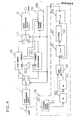
- Fig. 4 is a block diagram showing specific constructions of the control circuit 18 and the address generating circuit 19 of the embodiment of Fig. 2.
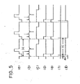
- Fig. 5 shows signal waveforms of the embodiments of Fig. 4.
- the control circuit 18 comprises a horizontal synchronizing signal detecting circuit 30 and a control signal generating circuit 40.
- the address generating circuit 19 comprises an up-down counter 190.
- the horizontal synchronizing signal generating circuit 30 comprises a differentiation circuit 31, monostable multivibrators (MMs) 32 and 33 and a gate circuit 34.
- the differentiation circuit 31 detects the edges of a horizontal synchronizing signal contained in an input video signal (indicated by (a) in Fig. 5), and generates a signal indicated by (b) in Fig. 5.
- the MM-32 is triggered by a horizontal synchronizing signal leading edge detecting pulse in signal (b) to generate a signal indicated by (c) in Fig. 5.
- the pulse width of signal (c) should be shorter than 1H but long enough to eliminate an equivalent pulse (normally found at the center point of a horizontal synchronizing signal) in the vertical flyback period.
- the MM 33 is triggered by the leading edge of the output signal (c) of the MM 32 and generates a signal having almost the same pulse width as the horizontal synchronizing signal, as shown by (d) in Fig. 5.
- a signal equivalent to the horizontal synchronizing signal as shown by (e) in Fig. 5 is obtained.
- signal (c) does not contain the abovementioned equivalent pulse.
- a synchronizing signal level detector may be used in place of the differentiation circuit 31.
- the control signal generating circuit 40 comprises a JK-flip-flop (JK-FF) 44, an a counter 42 and a D-flip-flop (D-FF) 43.
- the JK-FF 41 is "set” by the output (e) of the horizontal synchronizing signal detecting circuit 30.
- the a counter 42 starts counting and generates a pulse signal indicated by (f) in Fig. 5 after a time "a”.
- the JK-FF 41 is then "reset” by the pulse signal (f).
- the D-FF 43 reverses its state every time it receives a pulse signal (f) from the a counter to generate a control signal which reverses with intervals of "H” as shown by (g) in Fig. 5.
- first and second switches 14 and 17 changeover their contact terminals between terminals "a" and “b” in accordance with the control signal (g).
- the control signal (g) is directly inputted to the second memory 16 at a read/write designation (R/W) terminal while it is inputted to a R/W terminal of the first memory 15 via an . inverter 200; first and second memories 15 and 16 thus complementarily conduct the write and read operations alternately.
- the up/downcounter 190 counts up when the control signal (g) is at "HIGH” level and counts down when the control signal (g) is at "LOW” level.
- the count value is supplied as common address data to the first and second memories 15 and 16.
- the up/down counter 190 counts up, the output signal of the first transmission circuit 11 is written through the first switch 14 into the first memory 15, while the signal previously stored in the second memory 16 is inversely read from the second memory 16 and sent through the second switch 17 to the second transmission circuit 13.
- the up/down counter 190 counts down, the signal stored in the first memory 16 is inversely read from the first memory 15 and sent through the switch 17 to the second transmission circuit 13, while the output signal of the first transmission circuit 13 is written through the first switch 14 into the second memory 16. In this way the first and second memories 15 and 16 share the same address, thus simplifying circuit construction.
Landscapes
- Engineering & Computer Science (AREA)
- Multimedia (AREA)
- Signal Processing (AREA)
- Television Signal Processing For Recording (AREA)
- Information Transfer Systems (AREA)
Applications Claiming Priority (8)
| Application Number | Priority Date | Filing Date | Title |
|---|---|---|---|
| JP22211/85 | 1985-02-07 | ||
| JP22210/85 | 1985-02-07 | ||
| JP60022212A JPS61182386A (ja) | 1985-02-07 | 1985-02-07 | 信号処理装置 |
| JP60022210A JPS61182673A (ja) | 1985-02-07 | 1985-02-07 | 信号処理装置 |
| JP60022211A JPS61182385A (ja) | 1985-02-07 | 1985-02-07 | 信号処理装置 |
| JP22212/85 | 1985-02-07 | ||
| JP60052646A JPS61212182A (ja) | 1985-03-15 | 1985-03-15 | デイジタル信号処理装置 |
| JP52646/85 | 1985-03-15 |
Publications (2)
| Publication Number | Publication Date |
|---|---|
| EP0190942A2 true EP0190942A2 (fr) | 1986-08-13 |
| EP0190942A3 EP0190942A3 (fr) | 1987-12-09 |
Family
ID=27457723
Family Applications (1)
| Application Number | Title | Priority Date | Filing Date |
|---|---|---|---|
| EP86300847A Withdrawn EP0190942A3 (fr) | 1985-02-07 | 1986-02-07 | Dispositif de traitement de signal |
Country Status (1)
| Country | Link |
|---|---|
| EP (1) | EP0190942A3 (fr) |
Cited By (2)
| Publication number | Priority date | Publication date | Assignee | Title |
|---|---|---|---|---|
| EP0503891A3 (en) * | 1991-03-14 | 1993-03-03 | Matsushita Electric Industrial Co., Ltd. | Signal processing apparatus |
| EP0603983A3 (fr) * | 1992-12-24 | 1994-11-30 | Victor Company Of Japan | Appareil pour la reproduction d'un signal vidéo. |
Family Cites Families (3)
| Publication number | Priority date | Publication date | Assignee | Title |
|---|---|---|---|---|
| US4405942A (en) * | 1981-02-25 | 1983-09-20 | Telease, Inc. | Method and system for secure transmission and reception of video information, particularly for television |
| US4611231A (en) * | 1983-05-31 | 1986-09-09 | Matsushita Electric Industrial Co., Ltd. | Signal processing apparatus for a video signal |
| US4616270A (en) * | 1983-07-14 | 1986-10-07 | Victor Company Of Japan, Ltd. | Synchronizing signal separating circuit for a recording and reproducing apparatus |
-
1986
- 1986-02-07 EP EP86300847A patent/EP0190942A3/fr not_active Withdrawn
Cited By (4)
| Publication number | Priority date | Publication date | Assignee | Title |
|---|---|---|---|---|
| EP0503891A3 (en) * | 1991-03-14 | 1993-03-03 | Matsushita Electric Industrial Co., Ltd. | Signal processing apparatus |
| US5299003A (en) * | 1991-03-14 | 1994-03-29 | Matsushita Electric Industrial Co., Ltd. | Signal processing apparatus for changing the frequency characteristics of an input signal |
| EP0603983A3 (fr) * | 1992-12-24 | 1994-11-30 | Victor Company Of Japan | Appareil pour la reproduction d'un signal vidéo. |
| US5526136A (en) * | 1992-12-24 | 1996-06-11 | Victor Company Of Japan, Ltd. | Method and apparatus for reproducing a video signal subject to pre-emphasis |
Also Published As
| Publication number | Publication date |
|---|---|
| EP0190942A3 (fr) | 1987-12-09 |
Similar Documents
| Publication | Publication Date | Title |
|---|---|---|
| US4280133A (en) | Video signal processing circuit | |
| EP0159871A2 (fr) | Dispositif d'enregistrement et de reproduction pour des signaux de télétexte | |
| EP0227030B1 (fr) | Appareil pour l'enregistrement d'images fixes avec réduction de bruit aléatoire | |
| GB2063611A (en) | Signal reproducing circuits | |
| EP0128707B1 (fr) | Dispositif de traitement de signal pour un signal vidéo | |
| US4870507A (en) | Video tape recorder system | |
| EP0169013B1 (fr) | Dispositif d'enregistrement et de reproduction d'un signal vidéo | |
| US5535064A (en) | Information signal recording system using different compressing methods to obtain signals for recording along with a corresponding signal indicating the method of compression | |
| US5696847A (en) | Method and apparatus for processing a signal | |
| EP0101179A2 (fr) | Réduction des effets de diaphonie des signaux audio modulés, enregistrés dans des pistes adjacentes sur des supports d'enregistrement | |
| EP0334335B1 (fr) | Dispositif pour la transmission de signaux vidéo | |
| JPS607280A (ja) | 信号処理装置 | |
| JPS5880991A (ja) | 信号給受方式 | |
| JPS61182385A (ja) | 信号処理装置 | |
| JPS61182386A (ja) | 信号処理装置 | |
| JP2644502B2 (ja) | 画像信号再生装置 | |
| JPH0213993B2 (fr) | ||
| JPS63209283A (ja) | 磁気記録装置 | |
| JP2591356B2 (ja) | 記録再生装置 | |
| JPS63110882A (ja) | 録画再生装置 | |
| JPH0428184B2 (fr) | ||
| EP0603983A2 (fr) | Appareil pour la reproduction d'un signal vidéo | |
| JPH01221075A (ja) | 再生映像信号の処理装置 | |
| JPH0359504B2 (fr) | ||
| JPH0249579B2 (fr) |
Legal Events
| Date | Code | Title | Description |
|---|---|---|---|
| PUAI | Public reference made under article 153(3) epc to a published international application that has entered the european phase |
Free format text: ORIGINAL CODE: 0009012 |
|
| AK | Designated contracting states |
Kind code of ref document: A2 Designated state(s): DE FR GB |
|
| PUAL | Search report despatched |
Free format text: ORIGINAL CODE: 0009013 |
|
| AK | Designated contracting states |
Kind code of ref document: A3 Designated state(s): DE FR GB |
|
| STAA | Information on the status of an ep patent application or granted ep patent |
Free format text: STATUS: THE APPLICATION IS DEEMED TO BE WITHDRAWN |
|
| 18D | Application deemed to be withdrawn |
Effective date: 19880610 |
|
| RIN1 | Information on inventor provided before grant (corrected) |
Inventor name: KOBAYASHI, MASAAKI Inventor name: YONEYAMA, MASAYUKI |