EP0191147B1 - Chaudière à gaz ou à huile - Google Patents
Chaudière à gaz ou à huile Download PDFInfo
- Publication number
- EP0191147B1 EP0191147B1 EP85114540A EP85114540A EP0191147B1 EP 0191147 B1 EP0191147 B1 EP 0191147B1 EP 85114540 A EP85114540 A EP 85114540A EP 85114540 A EP85114540 A EP 85114540A EP 0191147 B1 EP0191147 B1 EP 0191147B1
- Authority
- EP
- European Patent Office
- Prior art keywords
- flue gas
- heating tube
- heating boiler
- heating
- ancillary
- Prior art date
- Legal status (The legal status is an assumption and is not a legal conclusion. Google has not performed a legal analysis and makes no representation as to the accuracy of the status listed.)
- Expired
Links
Images

Classifications
-
- F—MECHANICAL ENGINEERING; LIGHTING; HEATING; WEAPONS; BLASTING
- F23—COMBUSTION APPARATUS; COMBUSTION PROCESSES
- F23M—CASINGS, LININGS, WALLS OR DOORS SPECIALLY ADAPTED FOR COMBUSTION CHAMBERS, e.g. FIREBRIDGES; DEVICES FOR DEFLECTING AIR, FLAMES OR COMBUSTION PRODUCTS IN COMBUSTION CHAMBERS; SAFETY ARRANGEMENTS SPECIALLY ADAPTED FOR COMBUSTION APPARATUS; DETAILS OF COMBUSTION CHAMBERS, NOT OTHERWISE PROVIDED FOR
- F23M9/00—Baffles or deflectors for air or combustion products; Flame shields
-
- F—MECHANICAL ENGINEERING; LIGHTING; HEATING; WEAPONS; BLASTING
- F24—HEATING; RANGES; VENTILATING
- F24H—FLUID HEATERS, e.g. WATER OR AIR HEATERS, HAVING HEAT-GENERATING MEANS, e.g. HEAT PUMPS, IN GENERAL
- F24H1/00—Water heaters, e.g. boilers, continuous-flow heaters or water-storage heaters
- F24H1/22—Water heaters other than continuous-flow or water-storage heaters, e.g. water heaters for central heating
- F24H1/24—Water heaters other than continuous-flow or water-storage heaters, e.g. water heaters for central heating with water mantle surrounding the combustion chamber or chambers
- F24H1/26—Water heaters other than continuous-flow or water-storage heaters, e.g. water heaters for central heating with water mantle surrounding the combustion chamber or chambers the water mantle forming an integral body
- F24H1/28—Water heaters other than continuous-flow or water-storage heaters, e.g. water heaters for central heating with water mantle surrounding the combustion chamber or chambers the water mantle forming an integral body including one or more furnace or fire tubes
- F24H1/287—Water heaters other than continuous-flow or water-storage heaters, e.g. water heaters for central heating with water mantle surrounding the combustion chamber or chambers the water mantle forming an integral body including one or more furnace or fire tubes with the fire tubes arranged in line with the combustion chamber
-
- F—MECHANICAL ENGINEERING; LIGHTING; HEATING; WEAPONS; BLASTING
- F24—HEATING; RANGES; VENTILATING
- F24H—FLUID HEATERS, e.g. WATER OR AIR HEATERS, HAVING HEAT-GENERATING MEANS, e.g. HEAT PUMPS, IN GENERAL
- F24H8/00—Fluid heaters characterised by means for extracting latent heat from flue gases by means of condensation
-
- Y—GENERAL TAGGING OF NEW TECHNOLOGICAL DEVELOPMENTS; GENERAL TAGGING OF CROSS-SECTIONAL TECHNOLOGIES SPANNING OVER SEVERAL SECTIONS OF THE IPC; TECHNICAL SUBJECTS COVERED BY FORMER USPC CROSS-REFERENCE ART COLLECTIONS [XRACs] AND DIGESTS
- Y02—TECHNOLOGIES OR APPLICATIONS FOR MITIGATION OR ADAPTATION AGAINST CLIMATE CHANGE
- Y02B—CLIMATE CHANGE MITIGATION TECHNOLOGIES RELATED TO BUILDINGS, e.g. HOUSING, HOUSE APPLIANCES OR RELATED END-USER APPLICATIONS
- Y02B30/00—Energy efficient heating, ventilation or air conditioning [HVAC]
Definitions
- the invention relates to a boiler for oil or gas firing according to the preamble of claim 1.
- boilers are designed and operated in particular with a burner for heating oil in such a way that the exhaust gases leave the boiler at a temperature of around 150 ° C or more with the greatest possible utilization of the fuel calorific value, so that there is sufficient buoyancy and Chimney draft occurs and no chimney sooting occurs due to condensation of the water vapor content in the exhaust gases.
- calorific value upper calorific value
- condensing boilers before the flue gases leave the boiler or enter the chimney is that the dew point of the exhaust gas humidity is undershot and condensation of the water vapor portion in the exhaust gases which releases the heat of vaporization takes place.
- the invention has for its object to provide a boiler which is suitable and can be used as a condensing boiler for flue gas condensation operation, but which can also be converted simply as a boiler for normal operation without condensation and with normal exhaust gas temperatures of about 150 to 200 ° C can be operated where the chimney conditions do not allow a lower temperature of the flue gases when leaving the boiler.
- the object according to the invention is achieved by the features contained in the characterizing part of claim 1.
- the number of water-cooled secondary heating pipes leading down from the combustion chamber to the flue gas collector can be varied depending on the desired or required capacity of the boiler.
- the number of pot-like guide inserts can also be varied in each individual secondary heating tube, which, by generating many individual smaller flue gas jets, enables very high secondary heating surface loads and very high heat transfer values. This makes it possible to vary the flue gas temperatures at the flue gas outlet of the boiler in a very wide range. By removing all the pot-like guide inserts, the boiler can be operated with normal flue gas temperatures of 150 ° C or more, without the occurrence of flue gas condensate, if this is desired or is made necessary by the chimney conditions.
- the exhaust gas temperatures can be reduced so low to, for example, approximately 30 to 40 ° C that the dew point is fallen below at least in the lower half of the secondary heating tube and flue gas condensation occurs.
- the formation and retention of flue gas condensate in the flue gas and condensate collector leads to a reduction in the pollutant content of the exhaust gases discharged into the chimney.
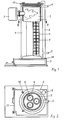
- the boiler contains a vertical, cylindrical water jacket 1 which surrounds a combustion chamber 2 for an oil or gas burner 3 at the upper end of the boiler.
- three secondary heating pipes 4 lead downward in water jacket 1 to a flue gas collector 5 at the lower end of the boiler.
- the water jacket 1 has at its upper end the flow connection 6 leading to the heating system and at its lower end the return connection 7 returning from the heating system.
- a flue gas discharge pipe 8 of the boiler leading to a chimney or the like is connected to the flue gas collector 5.
- Pot-like guide inserts 9 are arranged in each secondary heating tube 4.
- the guide inserts 9 extend with their upper edge part 10 to the wall of the secondary heating tube 4 and have radially directed passage openings 12 on their recessed pot part 11, which is radially distanced from the tube wall.
- the flue gases flowing downward in the secondary heating tube 4 are emitted by each pot-like conductive insert 9 steered into its interior and then directed radially outward from the through openings 12 in a plurality of individual flue gas jets against the wall of the secondary heating tube.
- the post-heating tube 4 has at least in its lower half a corrosion-resistant inside, for example by using corrosion-resistant material for the post-heating tube or by coating the post-heating tube on the flue gas side with a non-porous, corrosion-resistant coating, such as heat-resistant multilayer enamel.
- the pot-shaped guide inserts 9 are arranged in the secondary heating tube 4 so that they can be pulled out upwards and can be removed from the boiler by the combustion chamber 2, which is closed by a cleaning cover 13 on the top of the boiler.
- the guide inserts 9 are pushed onto a central support rod 14 and thereby connected to one another, the support rod 14 being detachably or permanently attached to the bottom of the lowermost guide insert 9 and by means of intermediate tubes 15, which are pushed onto the support rod 14 in alternation with the guide inserts, the height support of the guide inserts on the support rod 14 takes place.
- the bottom guide insert sits on supports 16 on the inside of the secondary heating tube. If the upper edge part 10 of the pot-like guide inserts is as close as possible to the wall of the secondary heating tube 4, the condensation water trickling down on the wall, particularly with the guide inserts located higher up, can again get into the interior of the hotter guide inserts compared to the pipe wall and evaporate there again.
- the advantageous effect is achieved in particular when firing the heating boiler with heating oil that a substantial part of the sulfur bound in the flue gas or in the condensed water is already excreted as a sulfur-containing residue in the pot-like guide inserts and accumulates as a crust on the pot bottom of the guide inserts.
- the crust can be easily removed from each individual guide insert at periodic cleaning intervals, since the guide insert column arranged on the holding rod 14 can be easily disassembled for cleaning purposes after being pulled out of the secondary heating tube.
- the boiler can also be conveniently switched to conventional boiler operation without flue gas condensation, for example in chimney conditions which, when the exhaust gases enter the chimney, do not have a lower temperature than the normal exhaust gas temperatures of about 150 allow up to 200 ° C.
- the flue gas collector 5 is formed under the mouth of the secondary heating pipe 4 with a condensate collecting space 17 which can be emptied and is corrosion-resistant, and into which the condensate draining down in the secondary heating tubes drips.
- the flue gas discharge pipe 8 is connected to the top of the flue gas collector 5, and the condensate collecting chamber 17 in the flue gas collector also extends below the confluence of the flue gas discharge pipe, so that any condensation that may still appear in the flue gas discharge pipe can drop the condensate from the flue gas discharge pipe back into the condensate collecting chamber .
- the flue gas collector 5 consists of a separately produced box, which is connected to the lower end of the boiler in a sealing manner and detachably by means of releasable clamp connections 18.
- This two-part construction of the boiler body and the flue gas collector makes it easy to provide and produce the flue gas collector or its walls by itself with an acid-resistant surface coating for the purpose of corrosion-resistant training.
- the condensate trap 17 is designed as a collector drawer that can be pulled out of the flue gas collector 5. If necessary, condensed water can be drained through the condensate drain socket of the collector drawer, for example into a neutralization device located outside the boiler, without pulling out or opening the collector drawer.
Landscapes
- Engineering & Computer Science (AREA)
- General Engineering & Computer Science (AREA)
- Chemical & Material Sciences (AREA)
- Combustion & Propulsion (AREA)
- Mechanical Engineering (AREA)
- Thermal Sciences (AREA)
- Physics & Mathematics (AREA)
- Incineration Of Waste (AREA)
- Heat-Exchange Devices With Radiators And Conduit Assemblies (AREA)
- Chimneys And Flues (AREA)
- Instantaneous Water Boilers, Portable Hot-Water Supply Apparatuses, And Control Of Portable Hot-Water Supply Apparatuses (AREA)
- Details Of Fluid Heaters (AREA)
- Fats And Perfumes (AREA)
Claims (6)
Priority Applications (1)
| Application Number | Priority Date | Filing Date | Title |
|---|---|---|---|
| AT85114540T ATE34216T1 (de) | 1985-01-29 | 1985-11-15 | Heizkessel fuer oel- oder gasfeuerung. |
Applications Claiming Priority (2)
| Application Number | Priority Date | Filing Date | Title |
|---|---|---|---|
| DE8502235U | 1985-01-29 | ||
| DE8502235U DE8502235U1 (de) | 1985-01-29 | 1985-01-29 | Heizkessel für Öl- oder Gasfeuerung |
Publications (2)
| Publication Number | Publication Date |
|---|---|
| EP0191147A1 EP0191147A1 (fr) | 1986-08-20 |
| EP0191147B1 true EP0191147B1 (fr) | 1988-05-11 |
Family
ID=6776767
Family Applications (1)
| Application Number | Title | Priority Date | Filing Date |
|---|---|---|---|
| EP85114540A Expired EP0191147B1 (fr) | 1985-01-29 | 1985-11-15 | Chaudière à gaz ou à huile |
Country Status (5)
| Country | Link |
|---|---|
| US (1) | US4624216A (fr) |
| EP (1) | EP0191147B1 (fr) |
| JP (1) | JPS61175442A (fr) |
| AT (1) | ATE34216T1 (fr) |
| DE (2) | DE8502235U1 (fr) |
Families Citing this family (5)
| Publication number | Priority date | Publication date | Assignee | Title |
|---|---|---|---|---|
| US5516278A (en) * | 1995-03-08 | 1996-05-14 | Aos Holding Company | Forced draft mixer and burner assembly with pressure distribution device |
| DE29814868U1 (de) | 1998-08-19 | 1999-12-30 | Hoval Interliz Ag, Vaduz | Heizkessel |
| FR2879726B1 (fr) | 2004-12-21 | 2007-02-23 | Frisquet Sa Sa | Chaudiere comportant un insert muni de coupelles place dans le tube de chauffe |
| FR2889295B1 (fr) * | 2005-07-29 | 2013-07-05 | Frisquet Sa | Chaudiere comportant un assemblage d'elements directeurs de fumee |
| FR2912210B1 (fr) | 2007-02-05 | 2013-01-11 | Frisquet Sa | Echangeur thermique pour chaudiere, chaudiere equipee d'un tel echangeur et procede de fabrication d'un tel echangeur |
Family Cites Families (5)
| Publication number | Priority date | Publication date | Assignee | Title |
|---|---|---|---|---|
| US1918935A (en) * | 1931-04-13 | 1933-07-18 | Orlin N Sellers | Furnace |
| DE1076869B (de) * | 1957-09-07 | 1960-03-03 | Andre Georges Vandevelde | Gleichmittig je in Rauchgasrohre, insbesondere fuer Sammelheizungskessel, einzuhaengendes Einsatzrohr |
| DE1189223B (de) * | 1958-05-28 | 1965-03-18 | W & F Dinkel | Flammenleiteinrichtung fuer mit fluessigem Brennstoff betriebene Feuerungen mit senkrecht angeordnetem Zerstaeuberbrenner |
| ZA834990B (en) * | 1982-07-20 | 1984-04-25 | Holden William J | Heat exchanger cleaner |
| EP0106344A3 (fr) * | 1982-10-19 | 1985-04-17 | Hans Dr. Viessmann | Chaudière de chauffage à condensation |
-
1985
- 1985-01-29 DE DE8502235U patent/DE8502235U1/de not_active Expired
- 1985-11-15 AT AT85114540T patent/ATE34216T1/de not_active IP Right Cessation
- 1985-11-15 EP EP85114540A patent/EP0191147B1/fr not_active Expired
- 1985-11-15 DE DE8585114540T patent/DE3562665D1/de not_active Expired
-
1986
- 1986-01-10 US US06/818,535 patent/US4624216A/en not_active Expired - Fee Related
- 1986-01-29 JP JP61016011A patent/JPS61175442A/ja active Pending
Also Published As
| Publication number | Publication date |
|---|---|
| ATE34216T1 (de) | 1988-05-15 |
| US4624216A (en) | 1986-11-25 |
| JPS61175442A (ja) | 1986-08-07 |
| DE8502235U1 (de) | 1986-05-28 |
| EP0191147A1 (fr) | 1986-08-20 |
| DE3562665D1 (en) | 1988-06-16 |
Similar Documents
| Publication | Publication Date | Title |
|---|---|---|
| DE2837004A1 (de) | Verfahren und heizungskessel zum erwaermen des heizwassers in einer warmwasser-zentralheizungsanlage, insbesondere fuer ein- und mehrfamilienwohnhaeuser | |
| DE2950901C2 (de) | Zentralheizungsanlage | |
| EP0191147B1 (fr) | Chaudière à gaz ou à huile | |
| DE2912986A1 (de) | Vorrichtung zur ausnuetzung der abgaswaerme | |
| DE617872C (de) | Kohlenstaubfeuerung | |
| DE19518076C2 (de) | Schornsteinsystem für einen Brennwertkessel | |
| DE2518836C2 (de) | Tauch-Heißgas-Flüssigkeitserhitzer | |
| AT404633B (de) | Kondensatableitung für mehrere jeweils einen brenner aufweisende brennwertheizgeräte | |
| DE3329777C2 (fr) | ||
| EP0981024B1 (fr) | Chaudière avec brûleur inversé | |
| DE3421112A1 (de) | Vorrichtung zum abfuehren von abgasen hoher temperatur, insb. von rauchgasen aus gebaeuden mit der bestandteile der abgase durch weitestgehende abkuehlung auf raumtemperatur zur kondensation gebracht werden, das kondensat abgefuehrt u. d. kondensationswaerme rueckgewonnen wird | |
| DE29807361U1 (de) | Heizungsgerät | |
| DE3442467C2 (de) | Niedertemperatur-Heizkessel | |
| DE2807166C2 (fr) | ||
| DE3151418A1 (de) | Niedrigtemperatur-heizverfahren mit ausnutzung des oberen heizwerts von brennstoffen | |
| CH639471A5 (en) | Method and device for incinerating pasty, liquid or gaseous industrial waste | |
| EP0148282A1 (fr) | Dispositif pour brûler des solides | |
| DE19837159A1 (de) | Heizkessel, insbesondere Brennwertkessel | |
| DE3837581C2 (fr) | ||
| DE814154C (de) | Stehender Rauchrohrkessel | |
| DE725479C (de) | Waesche- o. dgl. Kochkessel mit seitlichem Abzug fuer die Feuergase | |
| DE3304868A1 (de) | Feuerungstechnisches geraet | |
| AT146927B (de) | Stehender Rauchrohrkessel. | |
| AT32073B (de) | Kesselanlage. | |
| AT375168B (de) | Heizkessel fuer festbrennstoffe, insbesondere fuer zentralheizungen |
Legal Events
| Date | Code | Title | Description |
|---|---|---|---|
| PUAI | Public reference made under article 153(3) epc to a published international application that has entered the european phase |
Free format text: ORIGINAL CODE: 0009012 |
|
| AK | Designated contracting states |
Kind code of ref document: A1 Designated state(s): AT BE CH DE FR GB IT LI LU NL SE |
|
| 17P | Request for examination filed |
Effective date: 19870115 |
|
| 17Q | First examination report despatched |
Effective date: 19871014 |
|
| GRAA | (expected) grant |
Free format text: ORIGINAL CODE: 0009210 |
|
| AK | Designated contracting states |
Kind code of ref document: B1 Designated state(s): AT BE CH DE FR GB IT LI LU NL SE |
|
| REF | Corresponds to: |
Ref document number: 34216 Country of ref document: AT Date of ref document: 19880515 Kind code of ref document: T |
|
| GBT | Gb: translation of ep patent filed (gb section 77(6)(a)/1977) | ||
| REF | Corresponds to: |
Ref document number: 3562665 Country of ref document: DE Date of ref document: 19880616 |
|
| ET | Fr: translation filed | ||
| ITF | It: translation for a ep patent filed | ||
| PLBE | No opposition filed within time limit |
Free format text: ORIGINAL CODE: 0009261 |
|
| 26N | No opposition filed | ||
| ITTA | It: last paid annual fee | ||
| PGFP | Annual fee paid to national office [announced via postgrant information from national office to epo] |
Ref country code: DE Payment date: 19920922 Year of fee payment: 8 |
|
| PGFP | Annual fee paid to national office [announced via postgrant information from national office to epo] |
Ref country code: GB Payment date: 19920929 Year of fee payment: 8 |
|
| PGFP | Annual fee paid to national office [announced via postgrant information from national office to epo] |
Ref country code: FR Payment date: 19921002 Year of fee payment: 8 |
|
| PGFP | Annual fee paid to national office [announced via postgrant information from national office to epo] |
Ref country code: SE Payment date: 19921012 Year of fee payment: 8 |
|
| PGFP | Annual fee paid to national office [announced via postgrant information from national office to epo] |
Ref country code: LU Payment date: 19921014 Year of fee payment: 8 |
|
| PGFP | Annual fee paid to national office [announced via postgrant information from national office to epo] |
Ref country code: AT Payment date: 19921028 Year of fee payment: 8 |
|
| PGFP | Annual fee paid to national office [announced via postgrant information from national office to epo] |
Ref country code: BE Payment date: 19921104 Year of fee payment: 8 |
|
| PGFP | Annual fee paid to national office [announced via postgrant information from national office to epo] |
Ref country code: CH Payment date: 19921116 Year of fee payment: 8 |
|
| PGFP | Annual fee paid to national office [announced via postgrant information from national office to epo] |
Ref country code: NL Payment date: 19921130 Year of fee payment: 8 |
|
| EPTA | Lu: last paid annual fee | ||
| PG25 | Lapsed in a contracting state [announced via postgrant information from national office to epo] |
Ref country code: LU Free format text: LAPSE BECAUSE OF NON-PAYMENT OF DUE FEES Effective date: 19931115 Ref country code: GB Effective date: 19931115 Ref country code: AT Effective date: 19931115 |
|
| PG25 | Lapsed in a contracting state [announced via postgrant information from national office to epo] |
Ref country code: SE Effective date: 19931116 |
|
| PG25 | Lapsed in a contracting state [announced via postgrant information from national office to epo] |
Ref country code: LI Effective date: 19931130 Ref country code: CH Effective date: 19931130 Ref country code: BE Effective date: 19931130 |
|
| BERE | Be: lapsed |
Owner name: HOVAL INTERLIZ A.G. Effective date: 19931130 |
|
| PG25 | Lapsed in a contracting state [announced via postgrant information from national office to epo] |
Ref country code: NL Effective date: 19940601 |
|
| GBPC | Gb: european patent ceased through non-payment of renewal fee |
Effective date: 19931115 |
|
| NLV4 | Nl: lapsed or anulled due to non-payment of the annual fee | ||
| PG25 | Lapsed in a contracting state [announced via postgrant information from national office to epo] |
Ref country code: FR Effective date: 19940729 |
|
| REG | Reference to a national code |
Ref country code: CH Ref legal event code: PL |
|
| PG25 | Lapsed in a contracting state [announced via postgrant information from national office to epo] |
Ref country code: DE Effective date: 19940802 |
|
| REG | Reference to a national code |
Ref country code: FR Ref legal event code: ST |
|
| EUG | Se: european patent has lapsed |
Ref document number: 85114540.9 Effective date: 19940610 |