EP0191190A2 - Fenêtre ou porte ou vitrage fixe avec une vitre à l'épreuve des projectiles - Google Patents
Fenêtre ou porte ou vitrage fixe avec une vitre à l'épreuve des projectiles Download PDFInfo
- Publication number
- EP0191190A2 EP0191190A2 EP85116250A EP85116250A EP0191190A2 EP 0191190 A2 EP0191190 A2 EP 0191190A2 EP 85116250 A EP85116250 A EP 85116250A EP 85116250 A EP85116250 A EP 85116250A EP 0191190 A2 EP0191190 A2 EP 0191190A2
- Authority
- EP
- European Patent Office
- Prior art keywords
- window
- door
- frame
- profile
- fixed glazing
- Prior art date
- Legal status (The legal status is an assumption and is not a legal conclusion. Google has not performed a legal analysis and makes no representation as to the accuracy of the status listed.)
- Granted
Links
Images


Classifications
-
- E—FIXED CONSTRUCTIONS
- E06—DOORS, WINDOWS, SHUTTERS, OR ROLLER BLINDS IN GENERAL; LADDERS
- E06B—FIXED OR MOVABLE CLOSURES FOR OPENINGS IN BUILDINGS, VEHICLES, FENCES OR LIKE ENCLOSURES IN GENERAL, e.g. DOORS, WINDOWS, BLINDS, GATES
- E06B3/00—Window sashes, door leaves, or like elements for closing wall or like openings; Layout of fixed or moving closures, e.g. windows in wall or like openings; Features of rigidly-mounted outer frames relating to the mounting of wing frames
- E06B3/96—Corner joints or edge joints for windows, doors, or the like frames or wings
- E06B3/9616—Corner joints or edge joints for windows, doors, or the like frames or wings characterised by the sealing at the junction of the frame members
-
- E—FIXED CONSTRUCTIONS
- E06—DOORS, WINDOWS, SHUTTERS, OR ROLLER BLINDS IN GENERAL; LADDERS
- E06B—FIXED OR MOVABLE CLOSURES FOR OPENINGS IN BUILDINGS, VEHICLES, FENCES OR LIKE ENCLOSURES IN GENERAL, e.g. DOORS, WINDOWS, BLINDS, GATES
- E06B3/00—Window sashes, door leaves, or like elements for closing wall or like openings; Layout of fixed or moving closures, e.g. windows in wall or like openings; Features of rigidly-mounted outer frames relating to the mounting of wing frames
- E06B3/04—Wing frames not characterised by the manner of movement
- E06B3/263—Frames with special provision for insulation
- E06B3/26301—Frames with special provision for insulation with prefabricated insulating strips between two metal section members
- E06B3/26303—Frames with special provision for insulation with prefabricated insulating strips between two metal section members with thin strips, e.g. defining a hollow space between the metal section members
-
- E—FIXED CONSTRUCTIONS
- E06—DOORS, WINDOWS, SHUTTERS, OR ROLLER BLINDS IN GENERAL; LADDERS
- E06B—FIXED OR MOVABLE CLOSURES FOR OPENINGS IN BUILDINGS, VEHICLES, FENCES OR LIKE ENCLOSURES IN GENERAL, e.g. DOORS, WINDOWS, BLINDS, GATES
- E06B5/00—Doors, windows, or like closures for special purposes; Border constructions therefor
- E06B5/10—Doors, windows, or like closures for special purposes; Border constructions therefor for protection against air-raid or other war-like action; for other protective purposes
- E06B5/106—Frames for bullet-proof windows
-
- E—FIXED CONSTRUCTIONS
- E06—DOORS, WINDOWS, SHUTTERS, OR ROLLER BLINDS IN GENERAL; LADDERS
- E06B—FIXED OR MOVABLE CLOSURES FOR OPENINGS IN BUILDINGS, VEHICLES, FENCES OR LIKE ENCLOSURES IN GENERAL, e.g. DOORS, WINDOWS, BLINDS, GATES
- E06B3/00—Window sashes, door leaves, or like elements for closing wall or like openings; Layout of fixed or moving closures, e.g. windows in wall or like openings; Features of rigidly-mounted outer frames relating to the mounting of wing frames
- E06B3/04—Wing frames not characterised by the manner of movement
- E06B3/263—Frames with special provision for insulation
- E06B2003/26349—Details of insulating strips
- E06B2003/2635—Specific form characteristics
- E06B2003/26352—Specific form characteristics hollow
-
- E—FIXED CONSTRUCTIONS
- E06—DOORS, WINDOWS, SHUTTERS, OR ROLLER BLINDS IN GENERAL; LADDERS
- E06B—FIXED OR MOVABLE CLOSURES FOR OPENINGS IN BUILDINGS, VEHICLES, FENCES OR LIKE ENCLOSURES IN GENERAL, e.g. DOORS, WINDOWS, BLINDS, GATES
- E06B3/00—Window sashes, door leaves, or like elements for closing wall or like openings; Layout of fixed or moving closures, e.g. windows in wall or like openings; Features of rigidly-mounted outer frames relating to the mounting of wing frames
- E06B3/04—Wing frames not characterised by the manner of movement
- E06B3/263—Frames with special provision for insulation
- E06B2003/26349—Details of insulating strips
- E06B2003/26387—Performing extra functions
- E06B2003/26389—Holding sealing strips or forming sealing abutments
Definitions
- the invention relates to a window or a door or a fixed glazing with a bullet-proof pane, which is bordered by a frame formed by heat-insulated composite profiles, the composite profiles consisting of two metal profiles, the two mutually parallel, spaced apart insulating bars are connected to each other and the window or door frame is assigned a fixed frame made of thermally insulated composite profiles.
- Windows or doors or fixed glazing of this type are known, which are generally provided with insulating glazing which consists of two or three panes arranged at a distance from one another.
- a window or a door is also known (DE - GM 78 03 666), in which or in which the metal outer profile is provided with a chamber which is used for receiving a bulletproof plate. This construction is complex since the bulletproof plate has to be manufactured, assembled and fixed within the chamber.
- the invention has for its object to maintain the previous design system for the production of thermally insulated windows and doors and fixed glazing even if the construction is to be designed to be additionally bullet-resistant to the requirement for thermal insulation.
- the bullet-resistant outer profile is permitted and such a material choice is made for this outer professional that the connection of the outer profile with the insulating rods can be made in the joining process, that is to say by pressing a groove web of the outer profile onto the edge strip of the insulator rods.
- the special aluminum alloy from which the metal outer profile is made has an alloy component silicon between 0.6 to 0.8 percent and an alloy component magnesium. This choice of material ensures that the outer profile can be anodized, so that it can be subjected to the usual surface treatments after the composite with the insulating bars and with the metal inner profile has been carried out.
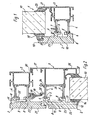
- the fixed glazing 1, the window or the door have thermally insulated profile frames 1, which consist of a metal insulating profile 2, a metal inner profile 3 and at least one insulating rod 4 made of a heat insulating material, which is arranged between the metal profiles and connected to them.
- the connection of the insulating rods 4 with the metal outer profile and the metal inner profile takes place in the joining process.
- the edge strips 5 of the insulating rods 4, which are trapezoidal in cross section, are received by anchoring grooves of the metal profiles, each of which is limited by a molding web 6 and a web 7, which serves as an abutment when the web 6 is molded onto the insulating rod 4
- the metal outer profiles 2 of the fixed glazing according to FIG. 1 and the frame and the sash frame according to FIG. 2 are designed as bullet-resistant or bulletproof, plate-shaped, extruded profiles which have beam-shaped support strips 8 on the inside.
- this beam-shaped support strips are the webs 6 and 7, which limit the anchoring grooves for the edge strips 5 of the insulating rods 4.
- Two adjacent support strips 8 together with the inner surface 9 of the metal outer profile 2 form a C-shaped receiving groove 10 for a corner connector 11, which is indicated in dash-dotted lines in FIG. 2.
- the metal outer profile of the casement of the window or the door is also provided with an anchoring groove 12 for a signal applied to the edge of the disc 13 sealing profile 14 equipped also, in the outer metal profile 2 of the fixed glazing shown in Fig. 1 for the signal applied at the edge of the disc 13 sealing profile 15 an anchoring 1 6 is provided.
- the metal outer profile of the sash frame has a support strip 8, whereby this overlap area is reinforced.
- the outer wall 23 of the metal outer profile 2 has a minimum thickness of 5 mm. The thickness of this outer wall 23 can also be 30 and more mm.
- the metal outer profile is advantageously produced from a special aluminum alloy with an alloy component silicon between 0.6 to 0.8 percent and an alloy proportion magnesium. This choice of material ensures that the metal outer profile 2 can be anodized.
- the metal The outer profile, which is made of the alloy mentioned, is tough and hard, so that it is also possible to form the webs 6 on the insulating rods 4 without cracks occurring in the foot region of the molding web.
- the metal inner profile 3 shown in FIGS. 1 and 2 has two anchoring grooves for the two insulating bars 4 running parallel to one another, these anchoring grooves likewise being limited by a molding web 2 4 and a web 25, which forms an abutment when the web 24 is molded on
- Metal inner profiles 3 are commercially available aluminum profiles.
- a glass retaining strip 26 or 27 is attached to the metal inner profile, which carries a sealing profile 28 or 29 resting against the edge of the pane 13.
- a Sealed profile 30 is attached, which forms a stop seal in the closed position of the wing
- the edge strips 31 of the insulating rod 4 which are approximately trapezoidal in cross section, are made of a hard material, while the central region of the insulating rod is made of relatively soft insulating material.
- the insulating rod 4 is hollow in its central region in the exemplary embodiment shown, that is to say it has an inner chamber 32, so that when the metal outer profile 2 is bombarded, the walls 33 of the chamber deform outwards and can assume the position indicated by dash-dotted lines in FIG. 3 . Due to this design of the insulating rod 4, the profile frame is dimensionally stable in the longitudinal direction and elastic in the transverse direction.
- FIGS. 4, 5 and 6 show a further exemplary embodiment for the design of the mitred frame corners of the connecting profiles and the corner connectors
- the corner connectors 11 cover the miter gap of the metal outer profile 2 of a finished window or door only in the area between the beam-shaped support strips 8.
- the corner connector 11 In order to increase the security against a bullet in the entire area of the profile frame, the corner connector 11 according to FIGS. 4, 5 and 6 is provided with an arrow-shaped miter reinforcement 34.
- This miter reinforcement 34 and the corner connector 11 consist of a high-strength aluminum alloy and are connected to form a structural unit. The two parts are connected by a rivet 40, by gluing or by spot welding.
- the orientation of the Gehrungsverste i Fung 34 which is advantageously designed as a sheet, is carried to the corner connector 11 at an angle of 45 ° to the Eckverbinderschenkein 41.42.
- This component which is used as a corner connector and as a miter reinforcement, is inserted into the miter of the metal outer profiles of the frame 43 and the sash 44, a groove-shaped recess 35 being machined beforehand in the miter region of each metal outer profile.
- the depth of the groove-shaped recess 35 corresponds to the total thickness of the components 11 and 34 and is based on the position of the insulation zone of the respective composite profile on the inner boundary of the receiving groove 10.
- FIG. 6 shows the position of the corner connector and the miter reinforcement 34 attached to it.
- the groove-shaped recesses 35 in the glare and in the window frame are shown in FIG. 2 in dashed lines.
- the miter reinforcement 34 is inserted into a groove-shaped recess of the metal outer profile 2, the miter reinforcement designed as a sheet metal can be supported in this area under load on the remaining support strips 8 and the load can be transferred via the insulating strips 4 to the inner window construction.
- the advantage of this concept lies in the fact that the arrow-shaped miter reinforcements 34 secure the miter area in a concealed manner and that the position of this miter reinforcement is ensured by the fixed connection to the corner connector 11 without any particular effort
- the corner connector 11 is also made of a high-strength aluminum alloy and has punched-out grooves 36 which serve to receive the lower parts of fastening pins 37, by means of which the corner connectors are mechanically connected to the outer, bullet-resistant metal outer profiles.
- the fastening pins 37 are driven into bores 38 of the metal outer profiles 2, which are provided in the mitred area of the profiles mentioned and which are offset from the grooves 36 of the corner connector legs. As a result of this offset, a force component is generated when a fastening pin 37 is driven into the associated groove 36 of a corner jointing leg, which causes the miter surfaces of the metal outer profiles 2 to be pressed together.
- the grooves 36 have an oblique chamfer 39.
- the miter area of the window or door frame or the frame of the fixed glazing is particularly secured by assigning the miter-shaped miter stiffener 34 to each corner connector 11, since the pre-filing miter is fully underpinned and the miter joint attachment also allows the miter to be spread apart by projectiles hitting the miter gap directly is prevented.
Landscapes
- Engineering & Computer Science (AREA)
- Civil Engineering (AREA)
- Structural Engineering (AREA)
- Securing Of Glass Panes Or The Like (AREA)
- Joining Of Glass To Other Materials (AREA)
- Special Wing (AREA)
- Wing Frames And Configurations (AREA)
- Surface Treatment Of Glass (AREA)
- Aiming, Guidance, Guns With A Light Source, Armor, Camouflage, And Targets (AREA)
- Table Devices Or Equipment (AREA)
- Joining Of Corner Units Of Frames Or Wings (AREA)
- Window Of Vehicle (AREA)
- Air Bags (AREA)
- Footwear And Its Accessory, Manufacturing Method And Apparatuses (AREA)
Priority Applications (1)
| Application Number | Priority Date | Filing Date | Title |
|---|---|---|---|
| AT85116250T ATE42797T1 (de) | 1985-02-14 | 1985-12-19 | Fenster oder tuer bzw. festverglasung mit einer schusssicheren scheibe. |
Applications Claiming Priority (2)
| Application Number | Priority Date | Filing Date | Title |
|---|---|---|---|
| DE3504989A DE3504989C2 (de) | 1985-02-14 | 1985-02-14 | Verglasung mit einer schußsicheren Scheibe |
| DE3504989 | 1985-02-14 |
Publications (3)
| Publication Number | Publication Date |
|---|---|
| EP0191190A2 true EP0191190A2 (fr) | 1986-08-20 |
| EP0191190A3 EP0191190A3 (en) | 1987-05-13 |
| EP0191190B1 EP0191190B1 (fr) | 1989-05-03 |
Family
ID=6262461
Family Applications (1)
| Application Number | Title | Priority Date | Filing Date |
|---|---|---|---|
| EP85116250A Expired EP0191190B1 (fr) | 1985-02-14 | 1985-12-19 | Fenêtre ou porte ou vitrage fixe avec une vitre à l'épreuve des projectiles |
Country Status (6)
| Country | Link |
|---|---|
| EP (1) | EP0191190B1 (fr) |
| AT (1) | ATE42797T1 (fr) |
| DE (2) | DE3504989C2 (fr) |
| DK (1) | DK164187C (fr) |
| FI (1) | FI81174C (fr) |
| NO (1) | NO164314C (fr) |
Cited By (7)
| Publication number | Priority date | Publication date | Assignee | Title |
|---|---|---|---|---|
| GB2201182A (en) * | 1987-04-07 | 1988-08-24 | Frederick Trenaman | Door/window frame |
| EP0283549A3 (en) * | 1987-03-17 | 1989-04-26 | Aluminia S.P.A. | Integral armour-clad, bullet-proof, double-shield closure means such as a door, window, shop-window and the like, of aluminium alloy |
| EP3034732A1 (fr) * | 2014-12-17 | 2016-06-22 | DORMA Deutschland GmbH | Installation de porte battante pliante |
| EP3034733A1 (fr) * | 2014-12-17 | 2016-06-22 | DORMA Deutschland GmbH | Installation de porte battante pliante |
| CN114482782A (zh) * | 2022-01-20 | 2022-05-13 | 华茗设计集团有限公司 | 一种被动式超低能耗建筑外窗及其实施方法 |
| CN115929170A (zh) * | 2022-12-28 | 2023-04-07 | 临沂市鸿泰门窗有限公司 | 一种高密封铝合金窗 |
| EP4517020A1 (fr) * | 2023-08-28 | 2025-03-05 | SCHÜCO International KG | Élément de façade |
Families Citing this family (3)
| Publication number | Priority date | Publication date | Assignee | Title |
|---|---|---|---|---|
| DE3728247C1 (de) * | 1987-08-25 | 1988-09-01 | Elke Saelzer | Verbundprofil fuer Rahmenschenkel oder Sprossen |
| DE4330292C2 (de) * | 1993-09-07 | 1999-02-25 | Sommer Metallbau Stahlbau Gmbh | Rahmenprofil, insbesondere Aluminiumrahmenprofil, für Sicherheitsfenster, -Türen oder Wandelemente |
| DE102004007164A1 (de) * | 2004-02-12 | 2005-09-22 | Sälzer Sicherheitstechnik GmbH | Sprengwirkungshemmendes Doppelfenster |
Family Cites Families (8)
| Publication number | Priority date | Publication date | Assignee | Title |
|---|---|---|---|---|
| DE1101734B (de) * | 1955-08-29 | 1961-03-09 | Aluminium Ind Ag | Verfahren zur Herstellung eines Winkelprofils aus Metall mit einer Kunststoffzwischenlage in Stabform, insbesondere fuer Fenster- oder Tuerrahmen |
| DE7717021U1 (de) * | 1977-05-28 | 1977-09-08 | Schueco Heinz Schuermann Gmbh & Co, 4800 Bielefeld | Basisprofil fuer den blendrahmen eines holz- oder kunststoffensters oder einer holz- oder kunststofftuer |
| DE7803666U1 (fr) * | 1978-05-24 | 1978-05-24 | Schueco Heinz Schuermann Gmbh & Co, 4800 Bielefeld | |
| DE2828905C2 (de) * | 1978-06-30 | 1982-05-13 | Schalm, Wolfgang, 8000 München | Verbundprofil bestehend aus zwei zueinander parallelen Metallteilen |
| DE8007525U1 (de) * | 1980-03-19 | 1980-07-24 | Goetz Metallbau Gmbh, 8360 Deggendorf | BeschuBhemmendes Metallfenster |
| DE8016077U1 (de) * | 1980-06-18 | 1980-11-13 | Rema Metall- Und Apparatebau Gmbh, 3000 Hannover | Beschußfestes Fenster |
| DE3025706A1 (de) * | 1980-07-07 | 1982-01-28 | Eberhard 7121 Freudental Keller | Vorrichtung zur herstellung von verbundprofilen, insbesondere fuer fenster, tueren o.dgl. |
| DE8022687U1 (de) * | 1980-08-26 | 1980-11-27 | Saelzer, Heinrich, 3550 Marburg | Kippfluegellager fuer fenster oder tueren schwerer ausfuehrung |
-
1985
- 1985-02-14 DE DE3504989A patent/DE3504989C2/de not_active Expired
- 1985-12-19 AT AT85116250T patent/ATE42797T1/de not_active IP Right Cessation
- 1985-12-19 DE DE8585116250T patent/DE3569955D1/de not_active Expired
- 1985-12-19 EP EP85116250A patent/EP0191190B1/fr not_active Expired
-
1986
- 1986-02-11 FI FI860614A patent/FI81174C/fi not_active IP Right Cessation
- 1986-02-13 NO NO860532A patent/NO164314C/no not_active IP Right Cessation
- 1986-02-13 DK DK069186A patent/DK164187C/da not_active IP Right Cessation
Cited By (8)
| Publication number | Priority date | Publication date | Assignee | Title |
|---|---|---|---|---|
| EP0283549A3 (en) * | 1987-03-17 | 1989-04-26 | Aluminia S.P.A. | Integral armour-clad, bullet-proof, double-shield closure means such as a door, window, shop-window and the like, of aluminium alloy |
| GB2201182A (en) * | 1987-04-07 | 1988-08-24 | Frederick Trenaman | Door/window frame |
| GB2201182B (en) * | 1987-04-07 | 1991-01-09 | Frederick Trenaman | Frame member |
| EP3034732A1 (fr) * | 2014-12-17 | 2016-06-22 | DORMA Deutschland GmbH | Installation de porte battante pliante |
| EP3034733A1 (fr) * | 2014-12-17 | 2016-06-22 | DORMA Deutschland GmbH | Installation de porte battante pliante |
| CN114482782A (zh) * | 2022-01-20 | 2022-05-13 | 华茗设计集团有限公司 | 一种被动式超低能耗建筑外窗及其实施方法 |
| CN115929170A (zh) * | 2022-12-28 | 2023-04-07 | 临沂市鸿泰门窗有限公司 | 一种高密封铝合金窗 |
| EP4517020A1 (fr) * | 2023-08-28 | 2025-03-05 | SCHÜCO International KG | Élément de façade |
Also Published As
| Publication number | Publication date |
|---|---|
| DK164187C (da) | 1992-10-05 |
| DE3569955D1 (en) | 1989-06-08 |
| ATE42797T1 (de) | 1989-05-15 |
| FI860614A0 (fi) | 1986-02-11 |
| DK164187B (da) | 1992-05-18 |
| EP0191190A3 (en) | 1987-05-13 |
| FI860614A7 (fi) | 1986-08-15 |
| DE3504989C2 (de) | 1987-04-09 |
| DK69186D0 (da) | 1986-02-13 |
| FI81174B (fi) | 1990-05-31 |
| FI81174C (fi) | 1990-09-10 |
| DE3504989A1 (de) | 1986-08-14 |
| EP0191190B1 (fr) | 1989-05-03 |
| NO164314B (no) | 1990-06-11 |
| NO164314C (no) | 1990-09-19 |
| NO860532L (no) | 1986-08-15 |
| DK69186A (da) | 1986-08-15 |
Similar Documents
| Publication | Publication Date | Title |
|---|---|---|
| DE69906277T2 (de) | Verbundprofil für die herstellung von fenster- und türrahmen | |
| WO2010063297A1 (fr) | Système de retenue pour vitres isolantes | |
| EP1106770B1 (fr) | Battant de fenêtre et fenêtre | |
| DE2915255A1 (de) | Verbundprofil | |
| EP1911923A2 (fr) | Latte isolante | |
| EP0191190B1 (fr) | Fenêtre ou porte ou vitrage fixe avec une vitre à l'épreuve des projectiles | |
| DE202014010902U1 (de) | Isolierelement für Fassaden- oder Lichtdachkonstruktionen | |
| EP0253983A2 (fr) | Fenêtre, porte ou vitrage fixe du type à l'épreuve des balles | |
| DE69026501T2 (de) | Fenster, tür oder ähnliche abschlüsse | |
| DE3532593A1 (de) | Extrudierter kunststoffhohlprofilstab fuer rahmen von fenstern und tueren | |
| DE2300281A1 (de) | Verstaerkungs-winkel fuer eckverbindungen von fenstern, tueren und aehnlichen bauteilen aus kunststoffprofilen zur erhoehung der stabilitaet und gestaltfestigkeit | |
| DE2313662A1 (de) | Fenster und verfahren zu seiner herstellung | |
| CH678747A5 (en) | Hinging facade window - has blocking portion pressing glazing via channel-section against supporting seal | |
| EP0746658B1 (fr) | Dispositif isolant pour façades | |
| DE2750351A1 (de) | Profilkonstruktion | |
| DE9206375U1 (de) | Tragwerk für Glasfassaden, -wände und/oder -dächer | |
| DE19851658A1 (de) | Fenster, Tür, Fassadenelement oder dergleichen sowie Verfahren zu deren Herstellung | |
| DE3506130A1 (de) | Durchschusshemmendes profil fuer fenster und tueren | |
| EP1683940A2 (fr) | Fenêtre ou porte avec vitrage collé | |
| DE4123604A1 (de) | Fassadenelement mit wenigstens einer glasscheibe | |
| EP0247356A2 (fr) | Vitrage pour des serres, jardins d'hiver ou similaires et vitres utilisables pour cela | |
| DE4314028A1 (de) | Mit einer Füllung versehener Flügel, insbesondere Fenster- oder Türflügel und Verfahren zu dessen Herstellung | |
| DE3134742A1 (de) | "fenster- oder tuerfluegel" | |
| AT249337B (de) | Fenster bzw. Tür | |
| DE1509172A1 (de) | Fenster bzw. Tuer,dessen bzw. deren feststehender Zargenrahmen und beweglicher Fluegelrahmen je aus einem Holzrahmen und einem damit verbundenen Metall- oder Kunststoffrahmen bestehen |
Legal Events
| Date | Code | Title | Description |
|---|---|---|---|
| PUAI | Public reference made under article 153(3) epc to a published international application that has entered the european phase |
Free format text: ORIGINAL CODE: 0009012 |
|
| AK | Designated contracting states |
Kind code of ref document: A2 Designated state(s): AT BE CH DE FR GB IT LI NL SE |
|
| PUAL | Search report despatched |
Free format text: ORIGINAL CODE: 0009013 |
|
| AK | Designated contracting states |
Kind code of ref document: A3 Designated state(s): AT BE CH DE FR GB IT LI NL SE |
|
| 17P | Request for examination filed |
Effective date: 19870407 |
|
| 17Q | First examination report despatched |
Effective date: 19880413 |
|
| RAP1 | Party data changed (applicant data changed or rights of an application transferred) |
Owner name: SCHUECO INTERNATIONAL GMBH & CO. |
|
| ITF | It: translation for a ep patent filed | ||
| GRAA | (expected) grant |
Free format text: ORIGINAL CODE: 0009210 |
|
| AK | Designated contracting states |
Kind code of ref document: B1 Designated state(s): AT BE CH DE FR GB IT LI NL SE |
|
| REF | Corresponds to: |
Ref document number: 42797 Country of ref document: AT Date of ref document: 19890515 Kind code of ref document: T |
|
| GBT | Gb: translation of ep patent filed (gb section 77(6)(a)/1977) | ||
| REF | Corresponds to: |
Ref document number: 3569955 Country of ref document: DE Date of ref document: 19890608 |
|
| ET | Fr: translation filed | ||
| PLBE | No opposition filed within time limit |
Free format text: ORIGINAL CODE: 0009261 |
|
| STAA | Information on the status of an ep patent application or granted ep patent |
Free format text: STATUS: NO OPPOSITION FILED WITHIN TIME LIMIT |
|
| 26N | No opposition filed | ||
| ITTA | It: last paid annual fee | ||
| EAL | Se: european patent in force in sweden |
Ref document number: 85116250.3 |
|
| PGFP | Annual fee paid to national office [announced via postgrant information from national office to epo] |
Ref country code: SE Payment date: 19991220 Year of fee payment: 15 |
|
| PG25 | Lapsed in a contracting state [announced via postgrant information from national office to epo] |
Ref country code: SE Free format text: LAPSE BECAUSE OF NON-PAYMENT OF DUE FEES Effective date: 20001220 |
|
| EUG | Se: european patent has lapsed |
Ref document number: 85116250.3 |
|
| REG | Reference to a national code |
Ref country code: GB Ref legal event code: IF02 |
|
| PGFP | Annual fee paid to national office [announced via postgrant information from national office to epo] |
Ref country code: GB Payment date: 20021126 Year of fee payment: 18 |
|
| PGFP | Annual fee paid to national office [announced via postgrant information from national office to epo] |
Ref country code: DE Payment date: 20021206 Year of fee payment: 18 |
|
| PGFP | Annual fee paid to national office [announced via postgrant information from national office to epo] |
Ref country code: NL Payment date: 20021217 Year of fee payment: 18 Ref country code: FR Payment date: 20021217 Year of fee payment: 18 |
|
| PGFP | Annual fee paid to national office [announced via postgrant information from national office to epo] |
Ref country code: AT Payment date: 20021223 Year of fee payment: 18 |
|
| PGFP | Annual fee paid to national office [announced via postgrant information from national office to epo] |
Ref country code: CH Payment date: 20021224 Year of fee payment: 18 |
|
| PGFP | Annual fee paid to national office [announced via postgrant information from national office to epo] |
Ref country code: BE Payment date: 20030107 Year of fee payment: 18 |
|
| PG25 | Lapsed in a contracting state [announced via postgrant information from national office to epo] |
Ref country code: GB Free format text: LAPSE BECAUSE OF NON-PAYMENT OF DUE FEES Effective date: 20031219 Ref country code: AT Free format text: LAPSE BECAUSE OF NON-PAYMENT OF DUE FEES Effective date: 20031219 |
|
| PG25 | Lapsed in a contracting state [announced via postgrant information from national office to epo] |
Ref country code: LI Free format text: LAPSE BECAUSE OF NON-PAYMENT OF DUE FEES Effective date: 20031231 Ref country code: CH Free format text: LAPSE BECAUSE OF NON-PAYMENT OF DUE FEES Effective date: 20031231 Ref country code: BE Free format text: LAPSE BECAUSE OF NON-PAYMENT OF DUE FEES Effective date: 20031231 |
|
| BERE | Be: lapsed |
Owner name: *SCHUCO INTERNATIONAL G.M.B.H. & CO. Effective date: 20031231 |
|
| PG25 | Lapsed in a contracting state [announced via postgrant information from national office to epo] |
Ref country code: NL Free format text: LAPSE BECAUSE OF NON-PAYMENT OF DUE FEES Effective date: 20040701 Ref country code: DE Free format text: LAPSE BECAUSE OF NON-PAYMENT OF DUE FEES Effective date: 20040701 |
|
| GBPC | Gb: european patent ceased through non-payment of renewal fee |
Effective date: 20031219 |
|
| REG | Reference to a national code |
Ref country code: CH Ref legal event code: PL |
|
| PG25 | Lapsed in a contracting state [announced via postgrant information from national office to epo] |
Ref country code: FR Free format text: LAPSE BECAUSE OF NON-PAYMENT OF DUE FEES Effective date: 20040831 |
|
| NLV4 | Nl: lapsed or anulled due to non-payment of the annual fee |
Effective date: 20040701 |
|
| REG | Reference to a national code |
Ref country code: FR Ref legal event code: ST |