EP0191469A2 - Aufzeichnungs- und/oder Wiedergabegerät für Tonsignale - Google Patents
Aufzeichnungs- und/oder Wiedergabegerät für Tonsignale Download PDFInfo
- Publication number
- EP0191469A2 EP0191469A2 EP86101757A EP86101757A EP0191469A2 EP 0191469 A2 EP0191469 A2 EP 0191469A2 EP 86101757 A EP86101757 A EP 86101757A EP 86101757 A EP86101757 A EP 86101757A EP 0191469 A2 EP0191469 A2 EP 0191469A2
- Authority
- EP
- European Patent Office
- Prior art keywords
- segments
- magnetic
- track
- rotary
- heads
- Prior art date
- Legal status (The legal status is an assumption and is not a legal conclusion. Google has not performed a legal analysis and makes no representation as to the accuracy of the status listed.)
- Granted
Links
Images




Classifications
-
- H—ELECTRICITY
- H04—ELECTRIC COMMUNICATION TECHNIQUE
- H04N—PICTORIAL COMMUNICATION, e.g. TELEVISION
- H04N5/00—Details of television systems
- H04N5/76—Television signal recording
- H04N5/78—Television signal recording using magnetic recording
- H04N5/782—Television signal recording using magnetic recording on tape
- H04N5/7824—Television signal recording using magnetic recording on tape with rotating magnetic heads
- H04N5/7826—Television signal recording using magnetic recording on tape with rotating magnetic heads involving helical scanning of the magnetic tape
- H04N5/78263—Television signal recording using magnetic recording on tape with rotating magnetic heads involving helical scanning of the magnetic tape for recording on tracks inclined relative to the direction of movement of the tape
-
- G—PHYSICS
- G11—INFORMATION STORAGE
- G11B—INFORMATION STORAGE BASED ON RELATIVE MOVEMENT BETWEEN RECORD CARRIER AND TRANSDUCER
- G11B5/00—Recording by magnetisation or demagnetisation of a record carrier; Reproducing by magnetic means; Record carriers therefor
- G11B5/008—Recording on, or reproducing or erasing from, magnetic tapes, sheets, e.g. cards, or wires
- G11B5/00813—Recording on, or reproducing or erasing from, magnetic tapes, sheets, e.g. cards, or wires magnetic tapes
- G11B5/00847—Recording on, or reproducing or erasing from, magnetic tapes, sheets, e.g. cards, or wires magnetic tapes on transverse tracks
- G11B5/0086—Recording on, or reproducing or erasing from, magnetic tapes, sheets, e.g. cards, or wires magnetic tapes on transverse tracks using cyclically driven heads providing segmented tracks
- G11B5/00865—Recording on, or reproducing or erasing from, magnetic tapes, sheets, e.g. cards, or wires magnetic tapes on transverse tracks using cyclically driven heads providing segmented tracks for transducing on more than one segment simultaneously
- G11B5/00873—Recording on, or reproducing or erasing from, magnetic tapes, sheets, e.g. cards, or wires magnetic tapes on transverse tracks using cyclically driven heads providing segmented tracks for transducing on more than one segment simultaneously the segments being disposed in different longitudinal zones of the tape
-
- G—PHYSICS
- G11—INFORMATION STORAGE
- G11B—INFORMATION STORAGE BASED ON RELATIVE MOVEMENT BETWEEN RECORD CARRIER AND TRANSDUCER
- G11B5/00—Recording by magnetisation or demagnetisation of a record carrier; Reproducing by magnetic means; Record carriers therefor
- G11B5/008—Recording on, or reproducing or erasing from, magnetic tapes, sheets, e.g. cards, or wires
- G11B5/00813—Recording on, or reproducing or erasing from, magnetic tapes, sheets, e.g. cards, or wires magnetic tapes
- G11B5/00878—Recording on, or reproducing or erasing from, magnetic tapes, sheets, e.g. cards, or wires magnetic tapes transducing different track configurations or formats on the same tape
-
- G—PHYSICS
- G11—INFORMATION STORAGE
- G11B—INFORMATION STORAGE BASED ON RELATIVE MOVEMENT BETWEEN RECORD CARRIER AND TRANSDUCER
- G11B5/00—Recording by magnetisation or demagnetisation of a record carrier; Reproducing by magnetic means; Record carriers therefor
- G11B5/48—Disposition or mounting of heads or head supports relative to record carriers ; arrangements of heads, e.g. for scanning the record carrier to increase the relative speed
- G11B5/52—Disposition or mounting of heads or head supports relative to record carriers ; arrangements of heads, e.g. for scanning the record carrier to increase the relative speed with simultaneous movement of head and record carrier, e.g. rotation of head
- G11B5/53—Disposition or mounting of heads on rotating support
- G11B5/531—Disposition of more than one recording or reproducing head on support rotating cyclically around an axis
- G11B5/534—Disposition of more than one recording or reproducing head on support rotating cyclically around an axis inclined relative to the direction of movement of the tape, e.g. for helicoidal scanning
Definitions
- This invention relates to a recording and/or reproducing apparatus of a rotary head type.
- Figure 1 illustrates a prior art tape format of an 8 mm video tape recorder, in which reference numeral 2 designates a magnetic tape, 3 a magnetic track, 4T a tape running direction upon recording, and 4H a head tracing direction.
- the length of the track 3 is made to correspond to 216 0 of a rotational angle of a rotary magnetic head, in which an audio signal is recorded on a segment 3A of 36° from the beginning of the track, and while a video signal is recorded on a segment 3V of the remaining 180°.
- the audio signal recorded on the segment 3A is converted to a PCM signal and the time base thereof is compressed so that one field amount thereof is positioned in this segment 3A.
- the video signal on the segment 3V is the signal at every field period.
- the luminance signal thereof is converted to an FM signal, while a carrier chrominance signal is low frequency converted. They are interleaved with respect to each other at every odd and even period.
- the tracks 3 are adjoining to one another, and every other track and the every other remaining track are arranged to be different in a so-called azimuth angle.
- the PCM signal is time-compressed to about 1/6 times and is recorded on an interval of about 30° at substantially the center of the segment 3A, while the remaining intervals before and after the same are assigned to guard segments.
- the length of this segment 3A is selected to be 36° and the PCM audio signal is recorded over the full length of this segment 3A.
- a rotary magnetic head assembly used in the 8 mm video tape recorder is constructed as shown in Figure 2.
- reference numerals 1A and 1B designate a pair of rotary magnetic heads. These heads are mounted on a rotary drum 5 with an angular spacing of 180° maintained therebetween and are rotated at a frame frequency of a video signal in the head tracing direction 4H. A tape 2 is wrapped slantwise around the rotation circumferential surface of the heads 1A and 1B over an angular range of a little larger than 216° and is transported in the predetermined direction 4T.
- the segment 3V is equally divided by 5 at every angle of 36°. Accordingly, the track 3 is divided into a total of 6 segments 1 to 6 along the lengthwise direction.
- the segment 1 to 6 only the segment 1, for example, is used at every track 3 to record the audio signal and in the second recording, for example, only the segment 2 is used at every track 3 to record the audio signal.
- the segments 1 to 6 only one segment is used at every track 3 to record the audio signal.
- the audio signal is recorded with the signal format exactly the same as the signal format of the PCM signal recorded on the segment 3A shown in Figure 1. Furthermore, the segments 1 to 6 can be used freely regardless of the sequential order.
- the same tape 2 can be freely used as a video tape or as an audio tape, and when the tape is used only as the audio tape, the recording time can be increased 6 times the recording time when the tape is used as the video tape. See published Japanese Patent 57-15287, corresponding to published European Application No. 85,578, incorporated herein by reference.
- the audio signal on the audio segment 3A or on the divided segments 1 to are recorded in the form of a PCM signal. Furthermore, the tape 2 is housed in a tape cassette and the tape cassette is of a small size. Accordingly, a tape recorder for the exclusive use of the audio signal can be realized by using the segment 3A, or the segments 1 to 6 in which case the tape recorder can be used as a headphone stereo player such as ⁇ . so-called WALKMA N (registered trademark).
- the diameter of one pair of magnetic heads of the rotary drum 5 is standardized to be 40 mm so that if the headphone stereo player is constructed with heads which are the same as the video player, it becomes large in size and heavy in weight.
- This invention is intended te solve-the above mentioned problems and provide a reduced size rotary drum still useful with 8 mm tape.
- recording and/or reproducing apparatus of a multi-segment type in which a slant magnetic track is formed on a tape by a rotary head.
- the magnetic track is divided into a plurality of segments.
- An audio signal is recorded on and/or reproduced from the divided segments.
- the diameter of the rotary drum can be reduced by selecting a certain rotational frequency of the rotary drum.
- the diameter of a rotary drum 15 is selected to be, for example, 1/3 the diameter of the drum 5 of Figure 2 , and small diameter drum 15 is rotated at a frequency, for example, three times the frame frequency of the rotary drum 5. Only during the interval of recording and/or reproducing an audio signal Sa is the tape 2 wrapped slantwise around the drum 15 and transported to record and/or reproduce the audio signal Sa of the corresponding segment.
- the audio signal Sa can be recorded on and/or reproduced from any one of the segments 1 to 6.
- the apparatus can be of a small size and of a light weight.
- Figure 4 is a plan view of a rotary Tagnetic head assembly according to this invention.
- Figure 5 shows a relationship between a head arrangement and a track pattern, seen from the side of the magnetic layer of a tape. However, in Figure 5, such a relationship is illustrated when the tape 2 is stopped running, for the sake of simplicity.
- the diameter of the drum is selected to be 1/3 the standardized value as a typical example, or is generally selected to be 1/odd number of the standardized value of the diameter.
- Reference numerals 11A to 13B represent the rotary magnetic heads, 15 the rotary drum, and 2 the magnetic tape in Figure 5.
- a first pair of rotary magnetic heads 11A and 11B are mounted on a rotary drum 15 with an angular spacing of 180° therebetween.
- the diameter of the drum 15 is selected to be 1/3 the diameter of the drum 5, and the track width and the azimuth angle of the heads 11A and 11B are made equal to those of the heads lA and lB of Figure 2.
- the angular position of the head 11A relative to the tracing direction 4H is taken as a reference point (0°) of the angle.
- the drum 15 is provided with a second pair of rotary magnetic heads 12A and 12B.
- the heads 12A and 12B have an angular spacing of 180° therebetween and are made equal to the heads lA and 1B in track width.
- the heads 12A and 12B are arranged at the angular positions which are the same as those of the heads 11A and 11B with respect to the tracing direction 4H. With respect to the track width direction, they are arranged to have a predetermined step difference H relative to the heads 11A and 11B.
- this step difference H is selected to be such that when the head 11A is positioned at the beginning (reference angle position) of the segment 1 of a certain track 3, the head 12A is positioned at the beginning of the segment 3 of the other track 3 at the end side of the tape 2 from the former track 3.
- Figure 5 shows the state when the movement of the tape 2 is stopped. When the tape 2 is transported in practice, as shown by a broken line, the track 3 is displaced to the end side of the tape 2 by the track width amount at the end position of the segment 5, so that the step difference H is increased by 1/2 a track width more than that shown by a solid line.
- the drum 15 is further provided with a pair of third rotary magnetic heads 13A and 13B.
- the_heads 13A and 13B have an angular spacing of 180° therebetween and are made equal to the heads lA and lB in track width.
- the heads 13A and 13B are arranged to have the angular positions the same as those of the heads 11A and 11B with respect to the tracing direction 4H, and are arranged to have the predetermined step difference H relative to the heads 12A and 12B with respect to the track width direction.
- the azimuth angles of the heads 12A to 13B are made equal to those of the heads lA, 1B or11A, 11B in response to the step difference H.
- heads 11A to 13B, and the drum 15, are rotated at a frequency three times the frame frequency in the direction 4H, while the tape 2 is wrapped slantwise around the rotation circumferential surface thereof over an angular range of 216°. Also, the tape 2 is transported at a predetermined speed. In this case, the tape 2 is wrapped around the heads 11A to 13B and the drum 15 with the angular spacing of 216°. Specifically, as shown in Figure 5, when the head 11A is positioned at the beginning of the track 3, the tape 2 is wrapped over the angular range WR of 216° therefrom.
- the diameter of the drum 15 is selected to be 1/3 the diameter of the standard-size drum 5, and also the drum 15 is rotated at a frequency three times the frequency of the drum 5, the tracing speed of the heads 11A to 13B relative to the track 3 becomes equal to the tracing speed of the heads lA and 1B of Figure 2 relative to the track 3.
- the heads 11A to 13B and the track 3 are put in a positional relation as shown in Figure 5, for three rotations of the drum 15, the heads 11A and 11B correctly trace the segments 1 and 2 of the track 3 once.
- the heads 12A and 12B correctly trace the segments 3 and 4 of the track 3 that is spaced from the former track by the step difference H.
- the heads 13A and 13B correctly trace the segments 5 and 6 of the track 3 that is spaced apart by another step difference H. Accordingly, by selecting pairs of the heads llA, 11B; 12A, 12B; or 13A, 13B, it is possible to freely record and/or reproduce the audio signal on and/or from all of the segments 1 to 6.
- FIG. 6 shows a recording system of the audio signal.
- Reference numeral 50 designates a generator circuit for generating various control signals used in the recording mode (and reproducing mode).
- This generator circuit includes a switch 51 to selectively switch on (and from) the one of the segments 1 to 6 of the track 3 on which the audio signal is recorded (and reproduced).
- the heads 11A to 13B and the drum 15 are rotated at the frequency three times the frame frequency through a rotary shaft 41 by a motor 42.
- a pair of pulse generating means 43A and 43B are mounted on, for example, the rotary shaft 41 which alternately produce a pulse at every half rotation of the heads 11A to 13B.
- These pulses are supplied to a generator circuit 44 which produces a square wave signal St which is synchronized with the rotation of the heads 11A to 13B, and is inverted in polarity at every half rotation of the heads 11A to 13B, as shown in Figure 8A.
- this generator circuit generates a square wave signal Sv which inverts its polarity at every 1.5 cycles of the signal St as shown in Figure 8B.
- the signals St and Sv are supplied to a drum servo circuit 45.
- a reference pulse with a frequency three times the frame frequency and a constant phase is supplied to the servo circuit 45.
- the servo output therefrom is supplied to the motor 42 so that the rotation of the heads 11A to 13B is locked to the constant phase.
- the rotation phase of the heads llA to 13B are locked such that they trace the tracks three times during one frame period (Ta + Tb), as shown by the solid lines.
- the heads 11A to 13A and the heads 11B to 13B are correctly tracked and positioned at the beginnings of the segments 1, and 3 at at least one of the three tracing times at the start time points of the periods Ta and Tb. Under the states shown by the broken lines, the mis-tracking occurred.
- the signals St and Sv are fed to the generator circuit 50 as signals indicative of the rotary phases of the heads 11A to 13B.
- Reference numeral 33 designates a capstan motor and 34 a capstan servo circuit.
- an audio signal (stereo signal) Sa is supplied through a terminal 21 to a PCM encoder 22 in which it is encoded to a PCM signal of a bi-phase system, the time base of which is compressed in response to the length of the segments 1 to 6, i.e., a PCM signal Sb with a format which is the same as that of the audio PCM signal in the 8 mm video tape recorder.
- the generator circuit 50 generates, on the basis of the output from the switch 51, an interval signal indicating the interval in the segments 1 to 6 of the track 3 in which the PCM signal Sb is recorded, or an interval signal Ss which, if it is recorded on, for example, the segment 1, becomes "1" during a period in which the segment 1 is traced by the heads 11A and 11B, as shown in Figure 8E.
- This signal Sb is fed to an adding circuit 23.
- This signal Sp is fed to the adding circuit 23.
- this signal Sp is the same as the pilot signal used in the 8 mm video tape recorder, and repeatedly changes its frequency at every field as frequency f 1 , f 2' f 3 and f 4 ..
- the frequency becomes f 1 or f3 during the period Ta and becomes f 2 or f 4 during the period Tb (for example, f 1 ⁇ 103kz and f 4 ⁇ 149k z ).
- This signal Sc is fed to a recording amplifier 24, while the generator circuit 50 generates a head switching signal Sh for switching the pairs of heads 11A, 11B; 12A, 12B; and 13A, 13B in response to the segments 1, 2; 3, 4; and 5, 6 based on the output from the switch 51.
- This signal Sh, and the signals Sv and Ss, are supplied to the amplifier 24.
- the audio signal Sa is sequentially recorded in the form of the signal Sc.
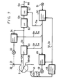
- Figure 7 illustrates a reproducing system of the audio signal Sa, in which, similarly to the recording mode, the heads 11A to 13B are rotated at the frequency three times the frame frequency by the servo circuit 45.
- the reproduced signals from the heads 11A to 13B are supplied to a playback amplifier 61, and the signals Sh, Sv, and Ss from the generator circuit 50 are also supplied to the amplifier 61, from which the signal Sc of the reproduced signals by the heads 11A to 13B is derived only during the period in which the interval specified by the switch 51 is traced by the heads llA, 11B; 12A, 12B; or 13A, 13B.
- This signal Sc is supplied to the servo circuit 34 and the transport speed of the tape 2 is controlled on the basis of the pilot signal Sp contained in the signal Sc.
- the tracking servo-control for the corresponding heads of the heads 11A to 13B is carried out.
- the signal Sc from the amplifier 61 is fed to a band pass filter 62 from which the PCM signal Sb is derived.
- This signal Sb is supplied to a PCM decoder 63, and is decoded to the original audio signal Sa.
- This signal Sa is delivered to a terminal 64.
- the audio signal Sa can be recorded on and/or reproduced from any of the segments 1 to 6.
- the apparatus can be small-sized and of light-weight.
- the encoder 22 and the decoder 63 there can be used circuits that are used in, for example, the 8 mm video tape recorder, so that the modification for the prior art system is minimal.
- Figures 9 and 10 are a plan view and an expanded view of another embodiment of the invention.
- the diameter of the drum is selected to be 1/2 the standardized value, as a typical example, wherein the diameter is reduced to 1/even number of the standardized diameter.
- the first pair of rotary magnetic heads 11A and 11B are mounted on the rotary drum 15 in such a manner that they have a predetermined and close angular spacing 8 maintained therebetween, and the head 11B follows the former head.
- the diameter of the drum 15 is selected to be 1/2 that of the drum 5, and the track width and azimuth angle of the heads 11A and 11B are selected the same as those of the heads lA and 1B.
- the angular position of the head 11A is taken as a reference point (0°) of the angle.
- the drum 15 is provided with the second pair of rotary magnetic heads 12A and 12B.
- the heads 12A and 12B are arranged to have an angular spacing 0 therebetween and are made equal to the heads 1A and 1B in track width.
- the heads 12A and 12B are mounted at the angular positions which are the same as those of the heads 11A and 11B with respect to the tracing direction 4H. They are arranged to have a predetermined step difference H relative to the heads 11A and 11B with respect to the track width direction.
- this step difference H is selected to be such that when the head 11A is positioned at the start point (position of reference angle) of the segment 1 in a certain track 3, the head 12A is positioned at the start point of the segment 4 in another track 3 at the end side of the tape 2 from the former track 3.
- the azimuth angle of the heads 12A, 123 is made equal to that of the heads lA, 1B or 1B, 1A in correspondence with the step difference H.
- heads 11A to 12B and the drum 15 are rotated at a frequency which is twice the frame frequency in the direction 4H.
- the tape 2 is wrapped obliquely around the rotation circumferential surface thereof over the angular range of 216°, and the tape 2 is transported at the predetermined speed.
- the tape 2 is wrapped around the heads 11A to 12B and the drum 15 over the angular range of 216°, as shown in Figure 10, when the head 11A is placed at the beginning of a certain track 3, the tape 2 is wrapped around the head over the angular range WR of 216° therefrom.
- the diameter of the drum 15 is selected to be 1/2 the diameter of the standard-size drum 5, and the drum 15 is rotated at the frequency twice the frequency of the drum 5, the tracing speed of the heads 11A to 12B relative to the track 3 is made equal to the tracing speed of the heads lA and lB relative to the track 3.
- the heads 11A to 12B and the tracks 3 are set in a positional relationship as shown in Figure 10 for one time per two rotaticns of the drum 15, the heads 11A and 11B trace the segments 1 to 3 of the track 3 accurately.
- the heads 12A and 12 B correctly trace the segments 4 to 6 of the track 3 that is distant from the former track by the step difference H. Accordingly, by selecting the heads 11A, 11B or 12A, 12B, it is possible to freely record and/or reproduce the audio signal on and/or from any of the segments 1 to 6.
- the recording system and the reproducing system are constructed the same way as those in Figures 6 and 7 so that the respective signals, if they are illustrated in correspondence with Figure 8, become as shown in Figure 11 Since the heads 11B and 12B are delayed from the heads 11A and 12A by the angular spacing 0, as shown in Figure 11D a relation between the heads 11B, 12B and the segments 1 to 3 and 4 to 6 is also delayed by the angular spacing 8. In correspondence therewith, during the field period Tb, the signal Ss and the following are delayed in like manner..
- the diameter of the drum 15 can be reduced to 1/2 the standard-size one, making the apparatus small in size and light in weight.
- the diameter of the drum 15 is selected to be 1/3 or 1/2 the standard-size value.
- the rotary frequency of the drum 15 is selected to be N times the frame frequency.
- the number of pairs of heads corresponding to the heads 1A and 1B is selected to be N pairs.
- the circuit is arranged as shown in Figures 4 and 5 when N is an odd number, and the circuit is arranged as shown in Figures 9 and 10 when N is an even number.
- the tape format ( Figure 1).of the 8 mm video tape recorder when the audio signal Sa is recorded on and/or reproduced only from the audio segment 3A, one pair of the heads 11A and 11B have to be used'as the heads, and the rotary frequency of the drum 15 has to be selected to be N times the frame frequency.
- the tape wrapping angle of the tape 2 around the drum 15 is selected to be N times 36°.
- the tape wrapping angle of the tape 2 has to be selected to be N/M times 36°.
- the angular positions of the heads llA, 11B; and 12A, 12B with respect to the tracing direction 4H can be made different.
- Figure 12 is a table illustrating design parameter choices for various drum diameter reductions.
- the audio signal Sa can be recorded on and/or reproduced from all of the segments 1 to 6.
- the apparatus can be made small in size and light in weight.
- the encoder 22 and the decoder 63 that are used in, for example, the 8 mm video tape recorder as they are, so that the modification for the prior art system is minimal.
Landscapes
- Engineering & Computer Science (AREA)
- Multimedia (AREA)
- Signal Processing (AREA)
- Recording Or Reproducing By Magnetic Means (AREA)
- Digital Magnetic Recording (AREA)
Applications Claiming Priority (2)
| Application Number | Priority Date | Filing Date | Title |
|---|---|---|---|
| JP27425/85 | 1985-02-14 | ||
| JP60027425A JPS61187103A (ja) | 1985-02-14 | 1985-02-14 | オ−デイオ信号の記録/再生装置 |
Publications (3)
| Publication Number | Publication Date |
|---|---|
| EP0191469A2 true EP0191469A2 (de) | 1986-08-20 |
| EP0191469A3 EP0191469A3 (en) | 1988-09-14 |
| EP0191469B1 EP0191469B1 (de) | 1992-09-16 |
Family
ID=12220752
Family Applications (1)
| Application Number | Title | Priority Date | Filing Date |
|---|---|---|---|
| EP86101757A Expired EP0191469B1 (de) | 1985-02-14 | 1986-02-12 | Aufzeichnungs- und/oder Wiedergabegerät für Tonsignale |
Country Status (5)
| Country | Link |
|---|---|
| US (1) | US4758911A (de) |
| EP (1) | EP0191469B1 (de) |
| JP (1) | JPS61187103A (de) |
| CA (1) | CA1301916C (de) |
| DE (1) | DE3686730T2 (de) |
Cited By (6)
| Publication number | Priority date | Publication date | Assignee | Title |
|---|---|---|---|---|
| EP0257991A3 (en) * | 1986-08-21 | 1989-05-10 | Sony Corporation | Methods of and apparatus for reproducing a digital signal |
| GB2173341B (en) * | 1985-04-02 | 1989-06-28 | Alps Electric Co Ltd | Signal transfer device for cylinder units |
| GB2225149A (en) * | 1988-10-10 | 1990-05-23 | Jacob Ezra | Video apparatus |
| EP0309287A3 (de) * | 1987-09-24 | 1990-08-08 | Kabushiki Kaisha Toshiba | Datenwiedergabegerät |
| DE4014744A1 (de) * | 1989-05-09 | 1990-11-15 | Mitsubishi Electric Corp | System und geraet zur digital-videosignalaufnahme |
| EP0382959A3 (de) * | 1988-02-16 | 1991-05-15 | Victor Company Of Japan, Limited | Aufzeichnungs- und Wiedergabegerät für digitale Signale |
Families Citing this family (14)
| Publication number | Priority date | Publication date | Assignee | Title |
|---|---|---|---|---|
| AU625311B2 (en) * | 1987-09-11 | 1992-07-09 | Sony Corporation | Recording apparatus |
| CA2066176C (en) * | 1989-11-09 | 1995-09-19 | Christopher Zook | Dual channel helical scan recorder |
| US5142422A (en) * | 1989-11-09 | 1992-08-25 | Exabyte Corporation | Dual channel helical recorder |
| ATE154720T1 (de) * | 1991-03-29 | 1997-07-15 | Sony Corp | Magnetkopf und ein digitaler magnetaufzeichnungskopf |
| JPH04302863A (ja) * | 1991-03-29 | 1992-10-26 | Sharp Corp | データ記録装置 |
| JP2982571B2 (ja) * | 1993-08-05 | 1999-11-22 | 日本ビクター株式会社 | デジタルデータ記録再生方法 |
| JPH1125547A (ja) * | 1997-06-30 | 1999-01-29 | Victor Co Of Japan Ltd | 回転ヘッド装置 |
| US6307701B1 (en) | 1998-10-20 | 2001-10-23 | Ecrix Corporation | Variable speed recording method and apparatus for a magnetic tape drive |
| US6246551B1 (en) | 1998-10-20 | 2001-06-12 | Ecrix Corporation | Overscan helical scan head for non-tracking tape subsystems reading at up to 1X speed and methods for simulation of same |
| US6308298B1 (en) | 1998-11-16 | 2001-10-23 | Ecrix Corporation | Method of reacquiring clock synchronization on a non-tracking helical scan tape device |
| US6603618B1 (en) | 1998-11-16 | 2003-08-05 | Exabyte Corporation | Method and system for monitoring and adjusting tape position using control data packets |
| JP4110672B2 (ja) * | 1999-05-31 | 2008-07-02 | ソニー株式会社 | 磁気記録再生装置及び記録再生方法 |
| US6624960B1 (en) | 2000-03-10 | 2003-09-23 | Exabyte Corporation | Current sensing drum/cleaning wheel positioning method and apparatus for magnetic storage system |
| US6364234B1 (en) | 2000-03-10 | 2002-04-02 | Michael Donald Langiano | Tape loop/slack prevention method and apparatus for tape drive |
Family Cites Families (6)
| Publication number | Priority date | Publication date | Assignee | Title |
|---|---|---|---|---|
| US3333063A (en) * | 1962-10-01 | 1967-07-25 | Ampex | Signal demodulating and combining circuit for wideband reproducing systems |
| US4179717A (en) * | 1978-02-01 | 1979-12-18 | Arvin Industries, Inc. | Method and apparatus for video signal recording |
| JPS5514541A (en) * | 1978-07-19 | 1980-02-01 | Nippon Hoso Kyokai <Nhk> | Magnetic recording and reproducing system |
| JPS58222402A (ja) * | 1982-02-02 | 1983-12-24 | Sony Corp | 情報信号の記録装置 |
| JPS58185009A (ja) * | 1982-04-23 | 1983-10-28 | Sony Corp | 磁気記録再生装置 |
| JPS59119519A (ja) * | 1982-12-27 | 1984-07-10 | Sony Corp | Pcm信号の記録装置 |
-
1985
- 1985-02-14 JP JP60027425A patent/JPS61187103A/ja active Pending
-
1986
- 1986-02-05 CA CA000501119A patent/CA1301916C/en not_active Expired - Lifetime
- 1986-02-11 US US06/828,172 patent/US4758911A/en not_active Expired - Fee Related
- 1986-02-12 EP EP86101757A patent/EP0191469B1/de not_active Expired
- 1986-02-12 DE DE8686101757T patent/DE3686730T2/de not_active Expired - Fee Related
Cited By (7)
| Publication number | Priority date | Publication date | Assignee | Title |
|---|---|---|---|---|
| GB2173341B (en) * | 1985-04-02 | 1989-06-28 | Alps Electric Co Ltd | Signal transfer device for cylinder units |
| EP0257991A3 (en) * | 1986-08-21 | 1989-05-10 | Sony Corporation | Methods of and apparatus for reproducing a digital signal |
| US4875111A (en) * | 1986-08-21 | 1989-10-17 | Sony Corporation | Apparatus for reproducing a digital signal |
| EP0309287A3 (de) * | 1987-09-24 | 1990-08-08 | Kabushiki Kaisha Toshiba | Datenwiedergabegerät |
| EP0382959A3 (de) * | 1988-02-16 | 1991-05-15 | Victor Company Of Japan, Limited | Aufzeichnungs- und Wiedergabegerät für digitale Signale |
| GB2225149A (en) * | 1988-10-10 | 1990-05-23 | Jacob Ezra | Video apparatus |
| DE4014744A1 (de) * | 1989-05-09 | 1990-11-15 | Mitsubishi Electric Corp | System und geraet zur digital-videosignalaufnahme |
Also Published As
| Publication number | Publication date |
|---|---|
| US4758911A (en) | 1988-07-19 |
| JPS61187103A (ja) | 1986-08-20 |
| DE3686730T2 (de) | 1993-02-04 |
| EP0191469B1 (de) | 1992-09-16 |
| DE3686730D1 (de) | 1992-10-22 |
| EP0191469A3 (en) | 1988-09-14 |
| CA1301916C (en) | 1992-05-26 |
Similar Documents
| Publication | Publication Date | Title |
|---|---|---|
| EP0191469B1 (de) | Aufzeichnungs- und/oder Wiedergabegerät für Tonsignale | |
| US4809118A (en) | PCM helical-scan magnetic record/playback systems | |
| EP0085578B1 (de) | Aufzeichnungsanordnung für ein Informationssignal das ein Videosignal und ein Audiosignal enthält | |
| EP0633560B1 (de) | Magnetisches Aufzeichnungs-und Wiedergabegerät | |
| US6246830B1 (en) | Apparatus for recording and reproducing video and audio signals in either analog or digital form | |
| EP0208536B1 (de) | Gerät zur Aufzeichnung und/oder Wiedergabe eines zusätzlichen Informationssignales | |
| US5359471A (en) | Recording and/or reproducing apparatus using rotary heads according to travelling speeds of a recording medium | |
| EP0085517B1 (de) | Anordnung zur Aufzeichnung von digitalen Signalen | |
| JPH0375953B2 (de) | ||
| EP0145331A3 (de) | Drehkopf-Ablenkungsgerät | |
| JP2733524B2 (ja) | 記録装置 | |
| US5126892A (en) | Rotating head type reproducing apparatus for reproducing an information signal from a record bearing medium having many parallel recording tracks and pilot signals of different frequencies | |
| KR100261197B1 (ko) | 기록 및 재생 장치 | |
| US5184254A (en) | Playback apparatus for playing back video information recorded on magnetic tape and providing smooth-frame still or slow motion video | |
| US5825971A (en) | Magnetic head replacement structure in helical scan magnetic recording and reproducing apparatus and method thereof | |
| US5057944A (en) | Multiplex rotating magnetic head system for multiply recording and erasing audio and video signals | |
| EP0098727A2 (de) | Aufzeichnungs- und Wiedergabesysteme mit Schrägspurabtastung | |
| JPH0550068B2 (de) | ||
| US5282096A (en) | Magnetic recording and playback apparatus | |
| EP0391728B1 (de) | Gerät zur magnetischen Schrägspur-Bandaufzeichnung und -wiedergabe, angepasst für Nachaufzeichnung | |
| GB2111293A (en) | Method of recording video signals | |
| JPS632104A (ja) | 磁気記録装置 | |
| US6678460B1 (en) | Magnetic reproducer and magnetic reproduction method | |
| JPS6254803A (ja) | 磁気記録装置 | |
| JPH01277301A (ja) | 回転ヘッド型記録または再生装置 |
Legal Events
| Date | Code | Title | Description |
|---|---|---|---|
| PUAI | Public reference made under article 153(3) epc to a published international application that has entered the european phase |
Free format text: ORIGINAL CODE: 0009012 |
|
| AK | Designated contracting states |
Kind code of ref document: A2 Designated state(s): DE GB NL |
|
| PUAL | Search report despatched |
Free format text: ORIGINAL CODE: 0009013 |
|
| AK | Designated contracting states |
Kind code of ref document: A3 Designated state(s): DE GB NL |
|
| 17P | Request for examination filed |
Effective date: 19881115 |
|
| 17Q | First examination report despatched |
Effective date: 19900508 |
|
| GRAA | (expected) grant |
Free format text: ORIGINAL CODE: 0009210 |
|
| AK | Designated contracting states |
Kind code of ref document: B1 Designated state(s): DE GB NL |
|
| REF | Corresponds to: |
Ref document number: 3686730 Country of ref document: DE Date of ref document: 19921022 |
|
| PLBE | No opposition filed within time limit |
Free format text: ORIGINAL CODE: 0009261 |
|
| STAA | Information on the status of an ep patent application or granted ep patent |
Free format text: STATUS: NO OPPOSITION FILED WITHIN TIME LIMIT |
|
| 26N | No opposition filed | ||
| PGFP | Annual fee paid to national office [announced via postgrant information from national office to epo] |
Ref country code: GB Payment date: 19970203 Year of fee payment: 12 |
|
| PGFP | Annual fee paid to national office [announced via postgrant information from national office to epo] |
Ref country code: DE Payment date: 19970221 Year of fee payment: 12 |
|
| PGFP | Annual fee paid to national office [announced via postgrant information from national office to epo] |
Ref country code: NL Payment date: 19970227 Year of fee payment: 12 |
|
| PG25 | Lapsed in a contracting state [announced via postgrant information from national office to epo] |
Ref country code: GB Free format text: LAPSE BECAUSE OF NON-PAYMENT OF DUE FEES Effective date: 19980212 |
|
| PG25 | Lapsed in a contracting state [announced via postgrant information from national office to epo] |
Ref country code: NL Free format text: LAPSE BECAUSE OF NON-PAYMENT OF DUE FEES Effective date: 19980901 |
|
| GBPC | Gb: european patent ceased through non-payment of renewal fee |
Effective date: 19980212 |
|
| NLV4 | Nl: lapsed or anulled due to non-payment of the annual fee |
Effective date: 19980901 |
|
| PG25 | Lapsed in a contracting state [announced via postgrant information from national office to epo] |
Ref country code: DE Free format text: LAPSE BECAUSE OF NON-PAYMENT OF DUE FEES Effective date: 19981103 |