EP0191494A2 - Türspiegel - Google Patents
Türspiegel Download PDFInfo
- Publication number
- EP0191494A2 EP0191494A2 EP86101850A EP86101850A EP0191494A2 EP 0191494 A2 EP0191494 A2 EP 0191494A2 EP 86101850 A EP86101850 A EP 86101850A EP 86101850 A EP86101850 A EP 86101850A EP 0191494 A2 EP0191494 A2 EP 0191494A2
- Authority
- EP
- European Patent Office
- Prior art keywords
- wires
- wire
- door mirror
- operation rod
- base
- Prior art date
- Legal status (The legal status is an assumption and is not a legal conclusion. Google has not performed a legal analysis and makes no representation as to the accuracy of the status listed.)
- Granted
Links
- 238000012856 packing Methods 0.000 description 5
- 230000005540 biological transmission Effects 0.000 description 3
- 239000000428 dust Substances 0.000 description 1
- 239000000463 material Substances 0.000 description 1
- 238000012986 modification Methods 0.000 description 1
- 230000004048 modification Effects 0.000 description 1
- 230000001932 seasonal effect Effects 0.000 description 1
- 230000000007 visual effect Effects 0.000 description 1
- XLYOFNOQVPJJNP-UHFFFAOYSA-N water Substances O XLYOFNOQVPJJNP-UHFFFAOYSA-N 0.000 description 1
Images





Classifications
-
- B—PERFORMING OPERATIONS; TRANSPORTING
- B60—VEHICLES IN GENERAL
- B60R—VEHICLES, VEHICLE FITTINGS, OR VEHICLE PARTS, NOT OTHERWISE PROVIDED FOR
- B60R1/00—Optical viewing arrangements; Real-time viewing arrangements for drivers or passengers using optical image capturing systems, e.g. cameras or video systems specially adapted for use in or on vehicles
- B60R1/02—Rear-view mirror arrangements
- B60R1/06—Rear-view mirror arrangements mounted on vehicle exterior
- B60R1/062—Rear-view mirror arrangements mounted on vehicle exterior with remote control for adjusting position
- B60R1/064—Rear-view mirror arrangements mounted on vehicle exterior with remote control for adjusting position by manually powered actuators
- B60R1/066—Rear-view mirror arrangements mounted on vehicle exterior with remote control for adjusting position by manually powered actuators for adjusting the mirror relative to its housing
- B60R1/068—Rear-view mirror arrangements mounted on vehicle exterior with remote control for adjusting position by manually powered actuators for adjusting the mirror relative to its housing using cables
-
- Y—GENERAL TAGGING OF NEW TECHNOLOGICAL DEVELOPMENTS; GENERAL TAGGING OF CROSS-SECTIONAL TECHNOLOGIES SPANNING OVER SEVERAL SECTIONS OF THE IPC; TECHNICAL SUBJECTS COVERED BY FORMER USPC CROSS-REFERENCE ART COLLECTIONS [XRACs] AND DIGESTS
- Y10—TECHNICAL SUBJECTS COVERED BY FORMER USPC
- Y10T—TECHNICAL SUBJECTS COVERED BY FORMER US CLASSIFICATION
- Y10T74/00—Machine element or mechanism
- Y10T74/20—Control lever and linkage systems
- Y10T74/20396—Hand operated
- Y10T74/20402—Flexible transmitter [e.g., Bowden cable]
- Y10T74/2042—Flexible transmitter [e.g., Bowden cable] and hand operator
- Y10T74/20432—Flexible transmitter [e.g., Bowden cable] and hand operator for moving a mirror
Definitions
- the present invention relates to a door mirror of the wire remote control type.
- each of the wires is inserted through a tube and introduced from the operation rod at a base fixed to the door into a mirror housing through the inside of the base and a fixed hollow shaft erected in the base.
- These wires are slid through the tubes, when they are operated by the operation rod, to swing the mirror body.
- the wires contract and expand to make it difficult to precisely operate the mirror, when temperature shows large change because of local and seasonal reasons, for example.
- collapsible door mirrors whose mirror housing can be collapsed along the side of the car body wherein a lock member is located between the mirror housing and a base which supports the mirror housing.
- the mirror housing is elastically shifted to a mirror setting position and held there by the lock member to stand wind pressure and the like.
- the lock member According to the elastic action of the lock member, the mirror housing is shifted in the direction of its coming near to or remote from the base. Relative positions of the mirror and the operation rod between which the wires are stretched are changed accordingly, and when the wires are to be stretched, therefore, it is needed that the wires are previously slackened to cover the positional change between the mirror and the operation rod.
- an engagement member - provided with engagement holes to correspond to the wires is attached to the bottom portion of the operation rod and that balls each connected to an end of each of the wires are engaged with the engagement holes, for example.
- the engagement member is swelled in the radius direction of the operation rod and each of the engagement holes in the engagement member is tapered in the direction of from the foremost end of the operation rod to the bottom thereof.
- Each of the wires is inserted through the engagement hole in this direction of from the foremost end of the operation rod to the bottom thereof and its ball connected to its last end is engaged with the engagement member.
- a sheet of packing made of rubber, for example, and provided with a hole through which the operation rod is inserted is attached to the bottom portion of the operation rod, covering the engagement member to prevent water from entering into the inside of the car from outside.
- some of the balls come out of the engagement holes toward the foremost end of the operation rod when the engagement member is shifted by the operation rod, thereby disturbing the precise transmission of the wires accordingly.
- the balls come out of the engagement member, thereby making it difficult to determine the length of the wires.
- a housing is attached through a support member, to a fixed shaft erected on a base which is fixed to a door, and a mirror freely swingably supported in the housing is operated by an operation rod, which is attached to the base, through plural wires.
- the slackening of each of the wires is absorbed by a slack-preventing member to precisely swing the mirror. Namely, each of the wires is tensioned to a certain extent or more by the slack-preventing member to precisely transmit the amount of the operation rod operated to the mirror.
- the slack-preventing member is provided every wire to precisely tension each of the wires.
- the slack-preventing member is provided with a wire pressing member and a spring member to fully tension each of the wires.
- a piece of plate spring serves as a slack absorbing member, which is simple in structure enough to prevent the wire from being slackened.
- the wire sliding portion is provided with a groove for guiding the wire to achieve precise wire pulling operation without tangling the wire.
- the groove formed through the wire sliding portion is covered by a lid to prevent the wire from coming out of the groove.
- the wire pressing member is a freely-rotatable pulley which enables each of the wires to be smoothly operated.
- tubes each keeping the wire inserted therethrough are fixed by a holder member in the base to prevent them from being slackened when the wires are pulled.
- the tubes through which the wires are inserted are positioned one another in a substantially close contact in the fixed shaft to enable each of the wires to be equally pulled.
- a washer is interposed between an end of each of the wires which is to be connected to an engagement member and the engagement member attached to the bottom of the operation rod, thereby preventing the connection between the engagement member and the wires from being slackened when the operation rod is operated.
- the object of the present invention is to provide a door mirror of the wire remote control type. wherein the slackening of the wires which extend from the operation rod to the inside of the housing through the base and the fixed shaft can be prevented to always keep the wires tensioned precisely, so that the angle of the mirror can be reliably adjusted.
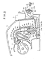
- a door mirror of the collapsible type comprises a base 2 fixed to the side of a door through a packing 1, a support means 4 freely rotatably attached to a fixed shaft 3 in the base 2, a mirror housing 5 attached to the support means 4 to house the latter, a mirror body base 6 freely swingably attached to the support means 4 through a pivot mechanism, a mirror body 7 freely detachably attached to the mirror body base 6, and a mirror 8 fitted into the mirror body 7 through cushion material (not shown), wherein three wires 9a, 9b and 9c connected to the mirror body base 6 can be pulled by the operation rod 10 attached to the base 2 to adjustably swing the mirror 8.
- the base 2 has a hollow portion through which the wires are passed, and the fixed shaft 3 has also an hole 3a through which the wires are passed.
- the wires 9a, 9b and 9c which are connected to the operation rod 10 and which are held in tubes 37a, 37b and 37c, respectively, are guided to the side of the support means 4, passing through the inside of the base 2 and the hole 3a of the fixed shaft 3.
- the support means includes a die-cast main bracket 11 and a resin-made sub-bracket 12.
- the main bracket 1 1 has a cylindrical portion 13 positioned at the collapsing center of the door mirror.
- the fixed shaft 3 located on the side of the base 2 is inserted through the cylindrical portion 1 3 and a push nut 29 is attached to that end of the fixed shaft 3 which is protruded from the cylindrical portion 13, through a coil spring 14, so that the main bracket 11 can be freely rotatably assembled on the base 2.
- the fixed shaft 3 is provided with a flange 15 at the bottom end thereof and the main bracket 11 is seated on this flange 15. Sandwiched between the upper surface of the flange 15 and the underside of the main bracket 11 is a stopper mechanism for stopping the main bracket 11 at a desired mirror setting position.
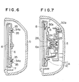
- plural lock members 16 attached to the main bracket 11 are elastically fitted into their corresponding lock recesses 17 on the flange 15, as shown in Fig. 5, and when the main bracket 11 is at the desired mirror setting position, the lock members 16 are fitted in their corresponding lock recesses 17 to stop the rotation of the main bracket 11.
- the lock members 16 which are in the lock recesses 17 hold the mirror rigid enough to stand wind pressure and the like.
- the lock members 16 come out of the lock recesses 17 to thereby,enable the door mirror to be collapsed along the door side.
- the lock members 16 mount on the upper surface of the flange 15 at this time, so that the support means 4 can be shifted upward.
- the main bracket 1 1 is provided with a slack preventing means for the wires 9a, 9b and 9c, as shown in Fig. 2.
- the slack preventing means comprises a guide post 18 formed on the main bracket 11, a coil spring 19, a wire pressing member 20 fitted onto the guide post 18 with the coil spring 19 interposed between them, and a wire sliding portion 21 formed on the foremost end of the wire pressing member 21, wherein the wires 9a, 9b and 9c which are on the wire sliding portion 21 can be tensioned by the coil spring 19.
- the wire sliding portion 21 is of semi-circular shape, whose one end faces the opening of the fixed shaft 3.
- the wire sliding portion 21 is provided with three grooves 22a, 22b and 22c in which the wires 9a, 9b and 9c are located, respectively.
- the wires 9a, 9b and 9c are guided, not tangled but parallel, by their corresponding grooves 22a, 22b and 22c toward the support means 4.
- the main bracket 11 is also provided with a stepped guide portion 23 for the wire pressing member 20.
- the sub-bracket 12 is fixed to the main bracket 11 by screws and it is provided with a cover 30 for covering the wire sliding portion 21. It is also provided at its front side with a pivot mechanism for supporting the mirror body base 6.
- the cover 30 encloses the wire pressing member 20 from three sides and overlaps the upper rim of the main bracket 11 to cover the upper surface of the wire sliding portion 21, thereby preventing dust and others from ap-. preaching the wire sliding portion 21.
- a part of the cover 30 extends downward and faces a cap 31 fitted onto the opened portion of the fixed shaft 3 to form a stopper 32 for stopping the cap 31 from coming out of the fixed shaft.
- the cap 31 is fitted onto the opened end of the fixed shaft 3 and provided with three holes 31 a, 31 b and 31 c through which the wires 9a, 9b and 9c are passed, and a flange 33 at the bottom end thereof, to which the foremost end of the stopper 32 is located adjacent. Therefore, the cap 31 can be easily attached to the fixed shaft 3 and also prevented from coming out of the fixed shaft 3 even if it should do so.
- the pivot mechanism a ring-like portion 24 continuous from the mirror body base 6, a seat 25 formed on the sub-bracket 12, and a press member 26 attached to the seat 25, wherein the ring-like portion 24 is inserted onto the seat 25 through a hole 6a in the center of the mirror body base 6 and sandwiched there between the seat 25 and the press member 26.
- the ring-like portion 24 is formed as a convexed sphere at the outer surface thereof and freely slidably and closely contacted with the concaved-sphere-like inner face of the seat 25.
- a part of the inner surface of the ring-like portion 24 is also freely slidably and closely contacted with the convexed - sphere-like outer face of the press member 26.
- the press member 26 is screwed to the seat 25.
- the ring-like portion 24 is thus sandwiched between the seat 25 and the press member 26 and held there freely shiftable along the spherical faces to freely swingably support the mirror body base 6.
- the mirror body base 6 thus supported is provided with plural engagement recesses 34 for engaging with the mirror body 7.
- the engagement rcess 74 is a cut-away portion at the sides of the mirror body base 6, having a rod 34a therein, which is fitted into a socket 35 on the back of the mirror body 7.
- the mirror body 7 can be thus attached to the mirror body base 6 detachably.
- the mirror body base 6 and the main bracket 11 are provided with stoppers 5 0a and 50b for limiting the swinging of the mirror body base 6.
- the stoppers 50a and 50b are ring-shaped projected pieces opposed to each other, and when the swinging angle of the mirror body 7 exceeds over a certain value, they are contacted with each other to limit the swinging of the mirror body 7. The unnecessary swinging of the mirror body base 6 can be thus limited and the detachment of the mirror body 7 can be easily achieved.
- each of the wires 9a, 9b and 9c is fixed to the engagement member 36 at the bottom end of the operation rod 10, while the wires in the tubes 37a, 37b and 37c are guided to the wire sliding portion 21, passing through the base 2, fixed shaft 3, and holes 31 a, 3 1 b and 31 c in the cap 31, and then connected to a connector plate 38 at their other ends, passing through holes in the sub-bracket 12 and mirror body base 6.
- the connector plate 38 is held in front of the mirror body base 6 by the tension of the wires 9a, 9b and 9c.
- the wires 9a, 9b and 9c are selectively pulled to swing the connector plate 38 together with the mirror body base 6, so that the angle of the mirror 8 can be adjusted.
- Each of the tubes 37a, 37b and 37c is flexible and they hold the wires 9a, 9b and 9c slidable therethrough.
- Those portions of the tubes 37a, 37b and 37c which are located in the base 2 are fixed, closely side by side, in a holder member 39 attached to the inner wall of the base 2, as shown in Figs. 2 and 8. Therefore, the tubes 37a, 37b and 37c are not slackened when the wires 9a, 9b and 9c in them are being pulled, thereby holding the wires to be precisely pulled.
- the hole 3a in the fixed shaft 3 is formed as a substantially regular triangle and the tubes 37a, 37b and 37c are located, closely contacted one another, at the vertexes of the triangle. The slackening of the tubes 37a, 37b and 37c in the fixed shaft can be thus prevented to improve the transmission efficiency of each of the wires 9a, 9b and 9c.
- the operation rod 1 0 has a knob 4 0 forcedly fitted onto the front end portion thereof, and the engagement member 36 forcedly fitted and fixed to the bottom end portion thereof through a washer 41.
- the engagement member 36 is swelled in the radius direction of the operation rod 10 and three holes 42 are formed in the engagement member 36 along the operation rod 10.
- Balls 4 3 each attached to the front end of each of the wires 9a, 9b and 9c are received in the holes 4 2 and held there, respectively.
- the wires 9a, 9b and 9c are thus connected to the operation rod 10.
- the washer 41 is positioned nearer to the front end of the operation rod 10 than the engagement member 36 is.
- the washer 41 has such a shape that can shield a part of each of the holes 42.
- the balls 4 3 in the holes 42 can be thus prevented from coming out of the holes 42 in the front end direction of the operation rod 10. Therefore, the wires 9a, 9b and 9c can be reliably operated by the operation rod 10 to achieve their precise transmission.
- the washer 4 1 is also provided with a portion 44 which is fitted into the hole 1 a of the packing 1 .
- This portion 44 includes a protrusion projected from the washer 41 and ring-shaped groove 44a formed along the outer circumference of the protrusion.
- the groove 44a receives the outer rim of the hole 1a a in the packing 1 to close the hole 1a. That portion of the groove 44a in which the outer rim of the hole 1 a is sandwiched is formed cylindrical and flexible to freely follow the swinging movement of the operation rod 10, thereby preventing the outer rim of the hole 1a from coming out of the portion 44.
- the hole 1 a is formed to have a diameter large enough to allow the knob 40 of the operation rod 10 to pass therethrough, but it is reliably and water-tightly closed by the washer 41.
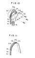
- Fig. 10 is a perspective view showing another example of the wire slack preventing means developed.
- the wire slack preventing means includes a coil spring 51, a pressing body 52 urged by the spring 51, a wire sliding portion 53 formed on a side of the pressing body 52, three grooves 54a, 54b and 54c through which the wires 9a, 9b and 9c are guided, and a cap member 55 which is screwed onto the wire sliding portion 53 to close the grooves 54a, 54b and 54c.
- the wires 9a, 9b and 9c can be prevented from coming out of the wire sliding portion 53 even if their tensions are changed quickly, thereby enabling them to be reliably operated.
- the wire sliding portion 53 can be formed on a side of the wire pressing body 52, thereby making it possible to freely select the passages through which the wires 9a, 9b and 9c are guided so as to leave the design of the door mirror free to a larger extent.
- Fig. 11 is a perspective view showing a further example of the wire slack preventing means.
- This wire slack preventing means is a curved plate spring provided with a wire sliding portion 56 having three grooves 57a, 57b and 57c formed thereon, through which the wires 9a, 9b and 9c are guided.
- the wire slack preventing means is arranged like this, neither the wire pressing body nor the spring member is needed to reduce the number of parts used.
- Fig. 12 is a perspective view showing a still further example of the wire slack preventing means.
- This wire slack preventing means includes a pulley-like wire pressing body 58, a coil spring 59 from which the wire pressing body 58 is freely rotatably suspended, a wire sliding portion 6 1 formed on the outer circumferential face of the wire pressing body 58, and three grooves 62a, 62b and 62c through which the wires 9a, 9b and 9c are guided, wherein the angle of the mirror 8 can be more smoothly adjusted.
- each of the wires 9a, 9b and 9c has served to tension all of the three wires 9a, 9b and 9c, but every wire may be tensioned by a wire slack preventing means. If so, each of the wires 9a, 9b and 9c can be more precisely tensioned.
Landscapes
- Engineering & Computer Science (AREA)
- Multimedia (AREA)
- Mechanical Engineering (AREA)
- Rear-View Mirror Devices That Are Mounted On The Exterior Of The Vehicle (AREA)
Applications Claiming Priority (8)
| Application Number | Priority Date | Filing Date | Title |
|---|---|---|---|
| JP25374/85 | 1985-02-13 | ||
| JP60025374A JPS61184142A (ja) | 1985-02-13 | 1985-02-13 | ドアミラ− |
| JP175260/85U | 1985-11-14 | ||
| JP1985175259U JPH0327877Y2 (de) | 1985-11-14 | 1985-11-14 | |
| JP175261/85U | 1985-11-14 | ||
| JP175259/85U | 1985-11-14 | ||
| JP1985175260U JPH0327878Y2 (de) | 1985-11-14 | 1985-11-14 | |
| JP17526185U JPH0247068Y2 (de) | 1985-11-14 | 1985-11-14 |
Publications (3)
| Publication Number | Publication Date |
|---|---|
| EP0191494A2 true EP0191494A2 (de) | 1986-08-20 |
| EP0191494A3 EP0191494A3 (en) | 1987-12-02 |
| EP0191494B1 EP0191494B1 (de) | 1991-04-24 |
Family
ID=27458299
Family Applications (1)
| Application Number | Title | Priority Date | Filing Date |
|---|---|---|---|
| EP86101850A Expired - Lifetime EP0191494B1 (de) | 1985-02-13 | 1986-02-13 | Türspiegel |
Country Status (3)
| Country | Link |
|---|---|
| US (1) | US4809561A (de) |
| EP (1) | EP0191494B1 (de) |
| DE (1) | DE3678855D1 (de) |
Cited By (2)
| Publication number | Priority date | Publication date | Assignee | Title |
|---|---|---|---|---|
| EP0498587A1 (de) * | 1991-02-04 | 1992-08-12 | Britax Rainsfords Pty. Limited | Neigungssteuerung eines Spiegels mit einem flexiblen Kabel |
| US6089723A (en) * | 1995-08-14 | 2000-07-18 | Kabushiki Kaisha Tokai Rika Denki Seisakusho | Mounting structure of base and base cover in door mirror for automobile |
Families Citing this family (11)
| Publication number | Priority date | Publication date | Assignee | Title |
|---|---|---|---|---|
| JPS62111244U (de) * | 1985-12-30 | 1987-07-15 | ||
| DE19913072B4 (de) | 1999-03-23 | 2005-10-13 | Mekra Lang Gmbh & Co. Kg | Außenspiegel für Kraftfahrzeuge |
| US6692131B1 (en) | 1999-04-30 | 2004-02-17 | Lang Mekra North America, Llc | Left and right rearview mirrors with common components |
| JP3889934B2 (ja) * | 2001-03-16 | 2007-03-07 | 矢崎総業株式会社 | ハーネス弛み吸収装置 |
| DE20106977U1 (de) | 2001-04-23 | 2002-08-29 | Mekra Lang Gmbh & Co Kg | Warneinrichtung in Kraftfahrzeugen |
| JP3954877B2 (ja) * | 2002-03-14 | 2007-08-08 | 株式会社ホンダロック | ドアミラー |
| US20040109249A1 (en) * | 2002-11-12 | 2004-06-10 | Magna Donnelly Mirrors North America, L.L.C. | Mirror system with interlock attachment for reflective element |
| US7303295B1 (en) * | 2004-06-24 | 2007-12-04 | Press Irving D | Rear view mirror assembly and system |
| US7448762B2 (en) * | 2006-09-13 | 2008-11-11 | Fu-Chu Su | Universal sideview mirror for car |
| US20080253008A1 (en) * | 2007-04-10 | 2008-10-16 | Milo Tseng | Foldable Exterior Rearview Mirror For Motor Vehicle |
| JP2010269705A (ja) * | 2009-05-21 | 2010-12-02 | Murakami Corp | 格納式アウターミラーのシャフト構造 |
Family Cites Families (18)
| Publication number | Priority date | Publication date | Assignee | Title |
|---|---|---|---|---|
| US2398860A (en) * | 1943-01-20 | 1946-04-23 | Marion P Mccaffrey | Material handling apparatus |
| US2931245A (en) * | 1957-11-29 | 1960-04-05 | Jervis Corp | Remote control device, particularly for an automotive rearview mirror |
| US3021962A (en) * | 1958-08-07 | 1962-02-20 | Manning Maxwell & Moore Inc | Crane control operating mechanism |
| US3030821A (en) * | 1958-12-03 | 1962-04-24 | Jervis Corp | Remote controlled apparatus |
| US3195370A (en) * | 1963-03-18 | 1965-07-20 | Hall C M Lamp Co | Remote control unit |
| US3290959A (en) * | 1964-07-02 | 1966-12-13 | Pacific Scientific Co | Flexible connector system |
| GB1136572A (en) * | 1965-02-16 | 1968-12-11 | Sheller Globe Corp | Remote control rear-view mirror |
| US3407684A (en) * | 1967-02-27 | 1968-10-29 | Kent Eng | Remote control mirror |
| US3444754A (en) * | 1967-04-07 | 1969-05-20 | C M Hall Lamp Co | Remote controlled motion transmitting device |
| US3474686A (en) * | 1967-04-07 | 1969-10-28 | C M Hall Lamp Co | Remote control device utilizing motion amplification |
| US3533303A (en) * | 1967-10-23 | 1970-10-13 | Jervis Corp | Right angle translator for remote control rearview mirrors |
| US3618420A (en) * | 1970-01-07 | 1971-11-09 | Casco Products Corp | Mechanical remote control apparatus |
| US3933058A (en) * | 1974-02-20 | 1976-01-20 | Tenna Corporation | Universal support for vehicle mirror |
| NL7512132A (nl) * | 1975-10-16 | 1977-04-19 | Koot Ind Bv | Inrichting voor het om twee onderling loodrechte assen verstellen van een autospiegel. |
| US4372177A (en) * | 1976-05-19 | 1983-02-08 | Murakami Kaimeido Co., Ltd. | Rear-view mirror control actuator |
| DE2715335A1 (de) * | 1977-04-06 | 1978-10-12 | Luchtenberg Gmbh & Co | Von innen verstellbarer aussenspiegel fuer fahrzeuge |
| DE2750904C2 (de) * | 1977-11-14 | 1983-10-20 | Brose Fahrzeugteile GmbH & Co KG, 8630 Coburg | Fensterheber, insbesondere für Kraftfahrzeuge |
| AU512874B2 (en) * | 1978-12-13 | 1980-10-30 | Lenhelen Proprietary Limited | Compensator for bowden cables |
-
1986
- 1986-02-12 US US06/828,525 patent/US4809561A/en not_active Expired - Fee Related
- 1986-02-13 DE DE8686101850T patent/DE3678855D1/de not_active Expired - Lifetime
- 1986-02-13 EP EP86101850A patent/EP0191494B1/de not_active Expired - Lifetime
Cited By (3)
| Publication number | Priority date | Publication date | Assignee | Title |
|---|---|---|---|---|
| EP0498587A1 (de) * | 1991-02-04 | 1992-08-12 | Britax Rainsfords Pty. Limited | Neigungssteuerung eines Spiegels mit einem flexiblen Kabel |
| US5205182A (en) * | 1991-02-04 | 1993-04-27 | Britax Rainsfords Pty Ltd | Cable actuated mirror tilt control |
| US6089723A (en) * | 1995-08-14 | 2000-07-18 | Kabushiki Kaisha Tokai Rika Denki Seisakusho | Mounting structure of base and base cover in door mirror for automobile |
Also Published As
| Publication number | Publication date |
|---|---|
| EP0191494B1 (de) | 1991-04-24 |
| DE3678855D1 (en) | 1991-05-29 |
| EP0191494A3 (en) | 1987-12-02 |
| US4809561A (en) | 1989-03-07 |
Similar Documents
| Publication | Publication Date | Title |
|---|---|---|
| US4809561A (en) | Door mirror | |
| US5752558A (en) | Tensioning device for a control cord of a blind assembly | |
| US6435444B1 (en) | Reel for a suspended sunshade | |
| US4620682A (en) | Golf bag stand | |
| US6733145B2 (en) | Folding softbox | |
| US4555166A (en) | Electric remote control mirror with half-ball portion | |
| US6279848B1 (en) | Reel having an improved reciprocating mechanism | |
| US20020165054A1 (en) | Front speed changing device | |
| EP1043508B1 (de) | Kugelgelenk für Kabelführung | |
| US5412889A (en) | Ornamental display assembly having reciprocating and rotating decorative elements | |
| KR100212692B1 (ko) | 차량외부의 가동형 백미러 조립체용 경사조절장치 | |
| JPH0247067Y2 (de) | ||
| JPH0327877Y2 (de) | ||
| JPH0327878Y2 (de) | ||
| JPH0247068Y2 (de) | ||
| JPH0327879Y2 (de) | ||
| JPH0327876Y2 (de) | ||
| CN217672798U (zh) | 一种新型夹持装置 | |
| KR970005887Y1 (ko) | 차량좌석용 요추받이 | |
| KR960014140B1 (ko) | 액정표시부 각도조절장치 | |
| KR840002251B1 (ko) | 벽면 취부형 전기기기 | |
| JP2905058B2 (ja) | 中通し釣竿 | |
| GB2250734A (en) | Stop and flow device for a watering can | |
| JPS6245390Y2 (de) | ||
| JPH0428277Y2 (de) |
Legal Events
| Date | Code | Title | Description |
|---|---|---|---|
| PUAI | Public reference made under article 153(3) epc to a published international application that has entered the european phase |
Free format text: ORIGINAL CODE: 0009012 |
|
| AK | Designated contracting states |
Kind code of ref document: A2 Designated state(s): DE FR GB |
|
| PUAL | Search report despatched |
Free format text: ORIGINAL CODE: 0009013 |
|
| AK | Designated contracting states |
Kind code of ref document: A3 Designated state(s): DE FR GB |
|
| 17P | Request for examination filed |
Effective date: 19880224 |
|
| 17Q | First examination report despatched |
Effective date: 19881219 |
|
| GRAA | (expected) grant |
Free format text: ORIGINAL CODE: 0009210 |
|
| AK | Designated contracting states |
Kind code of ref document: B1 Designated state(s): DE FR GB |
|
| REF | Corresponds to: |
Ref document number: 3678855 Country of ref document: DE Date of ref document: 19910529 |
|
| ET | Fr: translation filed | ||
| PLBE | No opposition filed within time limit |
Free format text: ORIGINAL CODE: 0009261 |
|
| STAA | Information on the status of an ep patent application or granted ep patent |
Free format text: STATUS: NO OPPOSITION FILED WITHIN TIME LIMIT |
|
| 26N | No opposition filed | ||
| PGFP | Annual fee paid to national office [announced via postgrant information from national office to epo] |
Ref country code: GB Payment date: 19980204 Year of fee payment: 13 |
|
| PGFP | Annual fee paid to national office [announced via postgrant information from national office to epo] |
Ref country code: FR Payment date: 19980210 Year of fee payment: 13 |
|
| PGFP | Annual fee paid to national office [announced via postgrant information from national office to epo] |
Ref country code: DE Payment date: 19980220 Year of fee payment: 13 |
|
| PG25 | Lapsed in a contracting state [announced via postgrant information from national office to epo] |
Ref country code: GB Free format text: LAPSE BECAUSE OF NON-PAYMENT OF DUE FEES Effective date: 19990213 |
|
| GBPC | Gb: european patent ceased through non-payment of renewal fee |
Effective date: 19990213 |
|
| PG25 | Lapsed in a contracting state [announced via postgrant information from national office to epo] |
Ref country code: FR Free format text: LAPSE BECAUSE OF NON-PAYMENT OF DUE FEES Effective date: 19991029 |
|
| PG25 | Lapsed in a contracting state [announced via postgrant information from national office to epo] |
Ref country code: DE Free format text: LAPSE BECAUSE OF NON-PAYMENT OF DUE FEES Effective date: 19991201 |
|
| REG | Reference to a national code |
Ref country code: FR Ref legal event code: ST |