EP0191552A2 - Accouplement flexible - Google Patents
Accouplement flexible Download PDFInfo
- Publication number
- EP0191552A2 EP0191552A2 EP86300252A EP86300252A EP0191552A2 EP 0191552 A2 EP0191552 A2 EP 0191552A2 EP 86300252 A EP86300252 A EP 86300252A EP 86300252 A EP86300252 A EP 86300252A EP 0191552 A2 EP0191552 A2 EP 0191552A2
- Authority
- EP
- European Patent Office
- Prior art keywords
- flexible
- hub
- coupling
- shaft
- flexible coupling
- Prior art date
- Legal status (The legal status is an assumption and is not a legal conclusion. Google has not performed a legal analysis and makes no representation as to the accuracy of the status listed.)
- Withdrawn
Links
Images

Classifications
-
- F—MECHANICAL ENGINEERING; LIGHTING; HEATING; WEAPONS; BLASTING
- F16—ENGINEERING ELEMENTS AND UNITS; GENERAL MEASURES FOR PRODUCING AND MAINTAINING EFFECTIVE FUNCTIONING OF MACHINES OR INSTALLATIONS; THERMAL INSULATION IN GENERAL
- F16D—COUPLINGS FOR TRANSMITTING ROTATION; CLUTCHES; BRAKES
- F16D3/00—Yielding couplings, i.e. with means permitting movement between the connected parts during the drive
- F16D3/50—Yielding couplings, i.e. with means permitting movement between the connected parts during the drive with the coupling parts connected by one or more intermediate members
- F16D3/78—Yielding couplings, i.e. with means permitting movement between the connected parts during the drive with the coupling parts connected by one or more intermediate members shaped as an elastic disc or flat ring, arranged perpendicular to the axis of the coupling parts, different sets of spots of the disc or ring being attached to each coupling part, e.g. Hardy couplings
- F16D3/79—Yielding couplings, i.e. with means permitting movement between the connected parts during the drive with the coupling parts connected by one or more intermediate members shaped as an elastic disc or flat ring, arranged perpendicular to the axis of the coupling parts, different sets of spots of the disc or ring being attached to each coupling part, e.g. Hardy couplings the disc or ring being metallic
Definitions
- This invention relates to flexible couplings and more particularly is concerned with disk-pack couplings.
- U.S. Patent Specification No. 4,055,966 discloseas a disk-pack coupling in which the disk-pack is mounted over the coupling hub which does reduce the overhung moment on the shafts. However, the disk-pack is still mounted between the flanges of the coupling hub and sleeve and the overhung moment while being reduced still causes problems.
- a flexible coupling for joining two longitudinally oriented shafts, each of said shafts being engaged by a bearing and extending therefrom toward said other shaft to a distal end where each of said shafts is spaced from the distal end of said other shaft, said flexible coupling comprising:
- the hub and the sleeve of the flexible coupling of the invention are each provided with a flange.
- the present invention overcomes the shortcomings of prior art disk-pack couplings by minimizing the overhung moment caused by the weight of the disk-pack.
- the disk-pack is mounted on the outside of the coupling hub flange which is as close as possible to the bearing housing of the driving and driven shaft of the coupled members.
- the disk-pack is bolted to a hub flange in a conventional manner, and the disk-pack is bolted to the sleeve flange by long bolts which extend through holes in the hub flange.
- an axial extension of the sleeve flange extends over the hub flange and the disk-pack, and the hub and sleeve flange are interlocking.
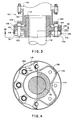
- FIG. 1 one embodiment of a disk-pack flexible coupling of the present invention, generally designated as 10, is mounted on a shaft 12 which is mounted in a bearing housing H.
- the coupling 10 includes a hub 14 which is keyed onto the shaft 12 in a conventional manner.
- a disk-pack 16 is fixed to a flange 18 of hub 14 by means of bolts 20, bushing 21, spacer washers 22 and nuts 24.
- the disk-pack 16 comprises laminates of flexible rings made of metal or a fibre-reinforced plastics material and allow coupling 10 to compensate for misalignment between shaft 12 which is the driving shaft, and the driven shaft which is not shown.
- Bolts 20 and spacer washer 22 have rounded surfaces 26 and 28 to prevent scoring or scratching of the disk-pack 16.
- Torque is transmitted from shaft 12 through hub 14 and disk-pack 16 to coupling sleeve 30.
- the disk-pack 16 is fixed to flange 32 of sleeve 30 by means of bolts 34, spacer rings 36 and nuts 38.
- Spacer rings 36 are placed in holes 40 in flange 18 of hub 14. Holes 40 are circular in the preferred embodiment and have a larger diameter than spacer rings 36. Holes 40 are cut into hub flange 18 so there is metal outside spacer rings 36 to contain the coupling in the event that the disk-pack 16 should fracture. It is to be understood, however, that any shaped passage could be formed in hub flange 18 to provide for spacer rings 36 and allow bolts 34 to pass therethrough.
- Sleeve 30 is fixed to spacer tube 42 in a conventional manner. Spacer tube 42 is fixed to the sleeve of the coupling for the driven shaft (not shown) and the torque from coupling 10 is transmitted through spacer tube 42 to that coupling.
- the structure of the coupling of the present invention allows the disk-pack to be mounted outside the hub flange 18 and close to bearing housing H thereby minimizing the over-hung moment of shaft 12.
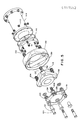
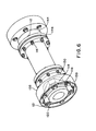
- FIG. 1 another embodiment of a disk-pack flexible coupling of the present invention, generally designated as 110, is mounted on a shaft 112 (not shown in Figures 5 and 6) which is mounted in a bearing housing.
- the coupling 110 includes hub 114 which is keyed onto the shaft 112 in a conventional manner.
- a disk-pack 116 is fixed to a flange 118 of hub 114 by means of bolts 120, bushings 121, spacer washers 122 and nuts 124.
- the disk-pack 116 comprises laminates of flexible rings made of metal or a fibre-reinforced plastics material and allows coupling 110 to compensate for misalignment between shaft 112 which is the driving shaft, and the driven shaft which is not shown.
- Torque is transmitted from shaft 112 through hub 114 and disk-pack 116 to a coupling sleeve 130.
- the disk-pack 116 is fixed to a flange 132 of sleeve 130 by means of bolts 134, bushings 135, spacer washers 136 and nuts 138.
- Spacer washers 137 are placed in holes 140 in flange 118 of hub 114.
- Sleeve flange 132 has an axial extension 139 which overlaps the hub flange 118 and the disk-pack 116 so that the sleeve flange 132 and its extension 139 interlock with the hub flange 118.
- the sleeve 130 is also connected by bolt 141 and nuts 142 to spacer tube 144.
- a shim pack 146 is interposed between the sleeve and spacer tube. It will be appreciated that such an interlocking arrangement will be generally more compact and weight-efficient than would be an arrangement in which juxtaposed hub and sleeve flanges were bolted together to effect a connection between the hub and sleeve. Furthermore, this arrangement provides for a protective shroud for the disk-pack. Holes 140 are cut into the hub flange 118 so that there is metal outside spacer rings 136 to contain the coupling in the event that the disk-pack 116 should fracture.
- Sleeve 130 is fixed to spacer tube 144 in a conventional manner. Spacer tube 144 is fixed to the sleeve of the coupling for the driven shaft (not shown) and the torque from coupling 110 is transmitted through spacer tube 144 to that coupling.
Landscapes
- Engineering & Computer Science (AREA)
- General Engineering & Computer Science (AREA)
- Mechanical Engineering (AREA)
- Packaging Of Annular Or Rod-Shaped Articles, Wearing Apparel, Cassettes, Or The Like (AREA)
- Shafts, Cranks, Connecting Bars, And Related Bearings (AREA)
- Motor Power Transmission Devices (AREA)
Applications Claiming Priority (4)
| Application Number | Priority Date | Filing Date | Title |
|---|---|---|---|
| US69211985A | 1985-01-17 | 1985-01-17 | |
| US79771185A | 1985-11-13 | 1985-11-13 | |
| US797711 | 1985-11-13 | ||
| US692119 | 2000-10-19 |
Publications (2)
| Publication Number | Publication Date |
|---|---|
| EP0191552A2 true EP0191552A2 (fr) | 1986-08-20 |
| EP0191552A3 EP0191552A3 (fr) | 1987-07-15 |
Family
ID=27104909
Family Applications (1)
| Application Number | Title | Priority Date | Filing Date |
|---|---|---|---|
| EP86300252A Withdrawn EP0191552A3 (fr) | 1985-01-17 | 1986-01-16 | Accouplement flexible |
Country Status (2)
| Country | Link |
|---|---|
| EP (1) | EP0191552A3 (fr) |
| JP (1) | JPS61180025A (fr) |
Cited By (4)
| Publication number | Priority date | Publication date | Assignee | Title |
|---|---|---|---|---|
| EP0636805A1 (fr) * | 1993-07-28 | 1995-02-01 | Kay Seven Co., Ltd. | Accouplement d'arbres |
| WO2007044605A3 (fr) * | 2005-10-07 | 2007-06-07 | Rexnord Ind Llc | Couplage pour chargeurs de disques emboites |
| EP2019222A2 (fr) | 2007-07-25 | 2009-01-28 | ATEC-Weiss GmbH & Co. KG | Accouplement d'arbre flexible doté d'un paquet de lamelles et d'éléments à engagement positif |
| CN108386457A (zh) * | 2018-05-16 | 2018-08-10 | 无锡创明传动工程有限公司 | 一种防止挠性件过度变形的保护结构 |
Families Citing this family (4)
| Publication number | Priority date | Publication date | Assignee | Title |
|---|---|---|---|---|
| JP5172038B1 (ja) * | 2012-07-31 | 2013-03-27 | 保男 平山 | 2次駆動装置、それを用いた板ばね式フレキシブルカップリング、それを用いた機械装置 |
| JP5343173B1 (ja) * | 2013-03-19 | 2013-11-13 | 保男 平山 | 板ばね式フレキシブルカップリング、それを用いた機械装置 |
| JP5611477B1 (ja) * | 2013-11-12 | 2014-10-22 | 保男 平山 | 主軸たわみ板フランジ及び主軸組合せたわみ板フランジ、それを用いた板ばね式フレキシブルカップリング、それを備えた機械装置 |
| CN106763264B (zh) * | 2016-12-27 | 2023-06-06 | 无锡创明传动工程有限公司 | 一种金属叠盘挠性联轴器 |
Family Cites Families (5)
| Publication number | Priority date | Publication date | Assignee | Title |
|---|---|---|---|---|
| US1326993A (en) * | 1918-05-01 | 1920-01-06 | Bertha E Thomas | Flexible shaft-coupling |
| US3654775A (en) * | 1970-03-16 | 1972-04-11 | Koppers Co Inc | Disc type flexible shaft coupling |
| JPS5250815Y2 (fr) * | 1971-07-08 | 1977-11-18 | ||
| US4055966A (en) * | 1975-10-10 | 1977-11-01 | Rexnord, Inc. | Torque transmission coupling |
| GB2065828B (en) * | 1979-12-18 | 1983-05-18 | Orsiflex Ltd | Flexible couplings |
-
1986
- 1986-01-16 EP EP86300252A patent/EP0191552A3/fr not_active Withdrawn
- 1986-01-16 JP JP714786A patent/JPS61180025A/ja active Pending
Cited By (10)
| Publication number | Priority date | Publication date | Assignee | Title |
|---|---|---|---|---|
| EP0636805A1 (fr) * | 1993-07-28 | 1995-02-01 | Kay Seven Co., Ltd. | Accouplement d'arbres |
| EP0771960A3 (fr) * | 1993-07-28 | 1997-06-04 | Kay Seven Co., Ltd. | Accouplement d'arlues |
| US5700197A (en) * | 1993-07-28 | 1997-12-23 | Kay Seven Co., Ltd. | Flexible shaft coupling having a plurality of driving side leaf spring members, a plurality of driven side leaf spring members and one relay member |
| WO2007044605A3 (fr) * | 2005-10-07 | 2007-06-07 | Rexnord Ind Llc | Couplage pour chargeurs de disques emboites |
| US7559845B2 (en) | 2005-10-07 | 2009-07-14 | Rexnord Industries, Llc | Nested disc pack coupling |
| EP2019222A2 (fr) | 2007-07-25 | 2009-01-28 | ATEC-Weiss GmbH & Co. KG | Accouplement d'arbre flexible doté d'un paquet de lamelles et d'éléments à engagement positif |
| DE102007035199A1 (de) | 2007-07-25 | 2009-02-05 | Atec-Weiss Gmbh & Co Kg | Flexible Wellenkupplung mit Lamellenpaket und Formschlusselementen |
| EP2019222A3 (fr) * | 2007-07-25 | 2009-06-03 | ATEC-Weiss GmbH & Co. KG | Accouplement d'arbre flexible doté d'un paquet de lamelles et d'éléments à engagement positif |
| CN108386457A (zh) * | 2018-05-16 | 2018-08-10 | 无锡创明传动工程有限公司 | 一种防止挠性件过度变形的保护结构 |
| CN108386457B (zh) * | 2018-05-16 | 2024-03-19 | 无锡创明传动工程有限公司 | 一种防止挠性件过度变形的保护结构 |
Also Published As
| Publication number | Publication date |
|---|---|
| EP0191552A3 (fr) | 1987-07-15 |
| JPS61180025A (ja) | 1986-08-12 |
Similar Documents
| Publication | Publication Date | Title |
|---|---|---|
| US4055966A (en) | Torque transmission coupling | |
| US4096711A (en) | Dual flex plate drive | |
| US9169078B2 (en) | Driving drum, deflecting drum, and tensioning drum for belt conveyors | |
| JPS6349088B2 (fr) | ||
| CA1154271A (fr) | Accouplements souples | |
| US20110001402A1 (en) | Generator flexible drive coupling | |
| EP0541724A4 (en) | Flexible drive transmitting coupling | |
| CA2956098C (fr) | Entrainement de melangeur de bobine ameliore | |
| CA1045399A (fr) | Combinaison pompe/moteur pour dispositif hydraulique | |
| US20070049379A1 (en) | Flexible coupling device | |
| JPH01145426A (ja) | 船内外機用カップリング | |
| US5765961A (en) | Adaptable mounting arrangement for shaft-carried speed reducer | |
| JPS61180025A (ja) | かみ合つたハブおよびスリーブのフランジをもつ逆取付けデイスクパツク継手 | |
| WO1991016550A1 (fr) | Accouplement articule servant a accoupler un element d'entrainement a un element entraine | |
| FR2409417A1 (fr) | Perfectionnements aux accouplements elastiques pour liaison d'arbres tournants | |
| RU2153607C2 (ru) | Гибкая муфта для трансмиссионных систем | |
| US5465804A (en) | Combination of a power steering pump and air conditioning compressor in an automotive vehicle | |
| US3545231A (en) | Multiple flexible element coupling | |
| EP1564059B1 (fr) | Accouplement entre moteur et transmission | |
| EP0666810B1 (fr) | Moteur a explosion pour navire et accouplement elastique associe | |
| US6524191B1 (en) | Inverted coupling assembly | |
| US4615687A (en) | Rotary drive coupling | |
| EP0332850B1 (fr) | Groupe propulseur et sa ramasseuse-hacheuse automotrice | |
| EP0382413A1 (fr) | Accouplement flexible et véhicule automobile le contenant | |
| US3237428A (en) | Mounting assembly for shaft mounted speed reducer |
Legal Events
| Date | Code | Title | Description |
|---|---|---|---|
| PUAI | Public reference made under article 153(3) epc to a published international application that has entered the european phase |
Free format text: ORIGINAL CODE: 0009012 |
|
| 17P | Request for examination filed |
Effective date: 19860131 |
|
| AK | Designated contracting states |
Kind code of ref document: A2 Designated state(s): CH DE FR GB IT LI NL |
|
| PUAL | Search report despatched |
Free format text: ORIGINAL CODE: 0009013 |
|
| AK | Designated contracting states |
Kind code of ref document: A3 Designated state(s): CH DE FR GB IT LI NL |
|
| 17Q | First examination report despatched |
Effective date: 19880701 |
|
| STAA | Information on the status of an ep patent application or granted ep patent |
Free format text: STATUS: THE APPLICATION IS DEEMED TO BE WITHDRAWN |
|
| 18D | Application deemed to be withdrawn |
Effective date: 19890112 |
|
| RIN1 | Information on inventor provided before grant (corrected) |
Inventor name: MUNYON, ROBERT E. Inventor name: CALISTRAT, MICHAEL M. |