EP0191574A2 - Zahnwurzelkanalerweiterer - Google Patents
Zahnwurzelkanalerweiterer Download PDFInfo
- Publication number
- EP0191574A2 EP0191574A2 EP86300550A EP86300550A EP0191574A2 EP 0191574 A2 EP0191574 A2 EP 0191574A2 EP 86300550 A EP86300550 A EP 86300550A EP 86300550 A EP86300550 A EP 86300550A EP 0191574 A2 EP0191574 A2 EP 0191574A2
- Authority
- EP
- European Patent Office
- Prior art keywords
- inner cylinder
- root canal
- cutting blade
- ball
- cylinder
- Prior art date
- Legal status (The legal status is an assumption and is not a legal conclusion. Google has not performed a legal analysis and makes no representation as to the accuracy of the status listed.)
- Withdrawn
Links
Images

Classifications
-
- A—HUMAN NECESSITIES
- A61—MEDICAL OR VETERINARY SCIENCE; HYGIENE
- A61C—DENTISTRY; APPARATUS OR METHODS FOR ORAL OR DENTAL HYGIENE
- A61C1/00—Dental machines for boring or cutting ; General features of dental machines or apparatus, e.g. hand-piece design
- A61C1/02—Dental machines for boring or cutting ; General features of dental machines or apparatus, e.g. hand-piece design characterised by the drive of the dental tools
- A61C1/07—Dental machines for boring or cutting ; General features of dental machines or apparatus, e.g. hand-piece design characterised by the drive of the dental tools with vibratory drive, e.g. ultrasonic waves
Definitions
- the present invention relates to a tooth root canal internal cutter which is used to enlarge the root canal of a tooth.
- an eccentric shaft formed at the tip of a rotary shaft is inserted into the hole of an inner cylinder which is itself inserted into an outer cylinder so as to be vertically movable, and the inner cylinder is moved vertically by the rotation of the rotary shaft.
- a cutting blade is installed on this inner cylinder and acts to enlarge the root canal of a tooth.
- the root canal of a tooth is not vertical, but is always curved, the degree of curvature being different for each person. Accordingly, with a cutter which performs only vertical movement, as described above, there have been disadvantages in that its cutting blade sometimes gets broken or a part of the tooth gets cut by mistake since cutting resistance becomes large and since the cutter is bent into a bow shape. In order to improve upon this conventional cutter which only moves vertically as described above, an improved type has been developed which is disclosed in, for-instance, Japanese Utility Model Examined Publication No. 56-21374.
- the cutter shown in this publication is arranged such that a further eccentric pin is provided on the tip of an eccentric shaft in the aforementioned cutter, and the inner cylinder is moved vertically by the-eccentric shaft, while the outer shaft is rotated by means of the pin, thereby effecting drilling-in and cutting operations.
- the present invention is designed to correct the aforementioned drawbacks, and it is an object of the present invention to provide a tooth root canal cutter which is capable of moving along the line of curvature in the curved portion of a root canal and which will not drill a hole in a portion away from the root canal by virtue of an arrangement in which the cutting blade, i.e. a dentist's file, generally moves vertically, and in which the rotation of the cutting blade and changes in the direction of the cutting blade only occur when cutting resistance is created by a curved portion in the root canal of a tooth.
- the cutting blade i.e. a dentist's file
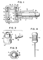
- Figs. 1 to 4 show a first embodiment of the present invention.
- reference numeral 1 denotes an outer cylinder, which is constituted by a vertical cylindrical portion la, and a horizontal cylindrical portion lb extending at right angles from approximately the intermediate portion of the vertical cylindrical portion la.
- Reference numeral 2 denotes an inner cylinder with the tip thereof being fitted into the horizontal cylindrical portion lb.
- Reference numeral 3 denotes a rotary shaft pivotally supported (i.e. the annular groove 3a thereof is prevented from coming off and, at the same time, rotatably supported by a plurality of projections formed on the inner cylinder 2) inside the inner cylinder 2, and its rightward end is coupled with a rotary driving section.
- this rotary shaft 3 is extended to the inside of the horizontal cylindrical portion lb and is, at the same time, pivotally supported by a ring 4. Furthermore, an eccentric shaft 3b is formed integrally at the tip thereof. Accordingly, the rotation of the rotary shaft 3 causes the eccentric shaft 3b to move in a circle.
- Reference numeral 5 denotes an inner cylinder inserted into the vertical cylindrical portion la of the outer cylinder 1 so as to be vertically movable.
- a guide groove 5a is formed along its periphery at an angle of approximately 90° facing the eccentric shaft 3b in the rotary shaft.
- a collar 6 fitted into the eccentric shaft 3b is inserted into this guide groove 5a.
- this collar 6 is to be provided so that smooth movement of the eccentric shaft 3b inside the guide groove 5a is enabled.
- the shaft 3b may be provided integrally with the collar 6.
- the collar 6 is abutted against the ring 4 so that it will not move in the axial direction of the eccentric shaft 3b.
- Reference numeral 7 denotes a grip cylinder inserted into the inside of the inner cylinder 5 such as to be vertically movable.
- a female threaded portion 7a is formed at the upper end thereof, and a collar 7b is formed at the lower end thereof.
- ball-receiving holes 7c are formed at several places near the lower end therof.
- a ball 8 is inserted into each of these ball-receiving holes 7c in such a manner as to partially project from the inner wall of the grip cylinder 7 but not to come off inwardly.
- the tapered portion 5b of the inner cylinder 5 is located at a position corresponding to these balls 8, and the tapered portion 5b presses the balls 8.
- the grip cylinder 7 is lowered with respect to the inner cylinder 5, the pressing action of the tapered portion 5b against the balls 8 disappear, so that the ball 8 can move within the ball receiving hole 7c.
- the collar 7b of the grip cylinder 7 is slidably in contact with the inner wall surface of the vertical cylindrical portion la of the outer cylinder, so that the ball 8 will not drop from the ball-receiving hole 7c.
- Reference numeral 9 denotes a screw cover which is screwably secured to the female threaded portion 7a of the grip cylinder 7, and a screw head 9a is formed so that it can be screwed along the inside of the grip cylinder 7.
- an annular recess 9b is formed on the underside of the screw cover 9, and a spring 10 is interposed.between this annular recess 9b and the annular recess 5c of the inner cylinder 5. Accordingly, the grip cylinder 7 is constantly pushed upward by this spring 10 with respect to the inner cylinder 5. Thus, the ball 8 is constantly pressed inwardly by means of the tapered portion 5b.
- Reference numeral 11 denotes a cutting blade in which a spiral cutting blade lla is formed at the tip thereof, and a grip llb having a sufficient size for insertion into the grip cylinder 7 is formed at the head thereof. In addition, a recess llc is formed on this grip llb. The balls 8 are to be positioned at this recess llc so that the cutting blade 11 will not come off. If the cutting blade 11 is intended to be withdrawn or inserted, the screw cover 9 is pushed down in opposition to the resilent force of the spring 10, and the grip cylinder 7 is lowered with respect to the inner cylinder 5. This allows each ball 8 to be movable, so that the grip llb of the cutting blade 11 can be inserted.
- the tip of the cutting blade 11 is inserted into the root canal of a tooth, the root canal is cut and expanded by the spiral cutting blade lla of the cutting blade 11 while the cutting blade 11 moves vertically.
- the curved configuration of a root canal varies from person to person, and the cutting blade 11 cannot move any further when it reaches a curved portion.
- cutting resistance is applied to the cutting blade 11, and the degree of resistance increases to a high level, so that the spiral cutting blade lla is to receive a rotary force. Accordingly, since the rotary force is transmitted to the inner cylinder 5 via the grip llb and the grip cylinder 7, slippage occurs between the inner cylinder 5 and the collar 6, thereby causing the inner cylinder 5 to rotate. As a result, the cutting blade 11 can then start to move along the curvature of the root canal.
- the guide groove in the inner cylinder in which an eccentric shaft for moving vertically in the inner cylinder is inserted extends around the circumference of the inner cylinder, so that the inner cylinder can be rotatable with respect to the eccentric shaft. Consequently, if cutting resistance is exerted on the cutting blade which is installed on the inner cylinder by means of the grip cylinder, the cutting blade rotates. Consequently, the cutting blade can be made to curve along the line of curvature of the root canal of a tooth, and the root canal is not enlarged any more than necessary since the cutting blade continuously advances along the root canal. In addition, there will be no such problems as a hole being drilled in a portion removed from a root canal.
- Figs. 5 to 8 describe a second embodiment of the present invention.
- portions that are identical with those shown in Figs. 1 to 4 are designated by the same reference numerals, and description thereof will be omitted.
- the guide groove 5a is formed around the entire periphery in the circumferential direction of the inner cylinder 5.
- the rotating angle of the inner cylinder 5 is not restricted as it is in the case of the first embodiment.
- the cutting blade can constantly rotate in response to the stress of cutting resistance applied to the cutting blade ll, so that the drilling of a hole in correspondence to the curve of a curved root canal can be effected more positively.
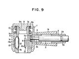
- Fig. 9 shows a third embodiment of the present invention.
- portions that are identical with those shown in Figs. 1 to 8 are designated by the same reference numerals, and description thereof will be omitted.
- spindle-shaped balls 12 are used, not spherical balls 8. Consequently, the ball-receiving hole 12a is also formed in the shape of a spindle.
- the size of the opening on the inner peripheral side of the grip cylinder 7 of the ball-receiving hole 12a is substantially smaller than the cross-sectional configuration of the spindle-shaped ball 12, so that the ball 12 does not fall.
- an elongated recess 13 is formed along the lower inner periphery of the inner cylinder 5 in correspondence with the ball-receiving hole 12a.
- a tapered surface 13a for pushing the head of the ball 12 is formed at the upper end thereof.
- the bottom surface of a recess 7d formed on the upper surface of the collar 7b of the grip cylinder 7 in correspondence with the recess 13 is so formed that it becomes gradually higher as it extends in the outward direction.
- the guide groove in the inner cylinder into which is inserted an eccentric shaft for moving the inner cylinder vertically, is elongated in the circumferential direction of the inner cylinder so that the inner cylinder can be rotatable. Consequently, if cutting resistance is exerted on the cutting blade which is installed on the inner cylinder by means of the grip cylinder, the cutting blade rotates. Hence, the cutting blade can be made to curve along the line of curvature of the root canal of a tooth and can drill a hole along the line of curvature.
Landscapes
- Health & Medical Sciences (AREA)
- Oral & Maxillofacial Surgery (AREA)
- Dentistry (AREA)
- Epidemiology (AREA)
- Life Sciences & Earth Sciences (AREA)
- Animal Behavior & Ethology (AREA)
- General Health & Medical Sciences (AREA)
- Public Health (AREA)
- Veterinary Medicine (AREA)
- Dental Tools And Instruments Or Auxiliary Dental Instruments (AREA)
Applications Claiming Priority (2)
| Application Number | Priority Date | Filing Date | Title |
|---|---|---|---|
| JP17314/85U | 1985-02-09 | ||
| JP1731485 | 1985-02-09 |
Publications (2)
| Publication Number | Publication Date |
|---|---|
| EP0191574A2 true EP0191574A2 (de) | 1986-08-20 |
| EP0191574A3 EP0191574A3 (de) | 1987-10-07 |
Family
ID=11940550
Family Applications (1)
| Application Number | Title | Priority Date | Filing Date |
|---|---|---|---|
| EP86300550A Withdrawn EP0191574A3 (de) | 1985-02-09 | 1986-01-28 | Zahnwurzelkanalerweiterer |
Country Status (1)
| Country | Link |
|---|---|
| EP (1) | EP0191574A3 (de) |
Cited By (4)
| Publication number | Priority date | Publication date | Assignee | Title |
|---|---|---|---|---|
| US4940410A (en) * | 1987-08-24 | 1990-07-10 | Dentalwerk Burmoos Gesellschaft M.B.H. | Dental tool holder |
| EP0360161A3 (de) * | 1988-09-20 | 1991-01-30 | Mikrona Technologie Ag | Gerät zur Zahnbehandlung |
| EP2754406A1 (de) * | 2013-01-14 | 2014-07-16 | W & H Dentalwerk Bürmoos GmbH | Medizinisches, insbesondere dentales, Handstück |
| CN110891516A (zh) * | 2017-07-24 | 2020-03-17 | 铃木计芳 | 铰刀的电动式往复运动产生件及带铰刀的电动式往复运动产生件 |
Family Cites Families (3)
| Publication number | Priority date | Publication date | Assignee | Title |
|---|---|---|---|---|
| AT353947B (de) * | 1973-08-28 | 1979-12-10 | Buermoos Dentalwerk | Feilwerkzeug mit oszillierendem werkzeughalter |
| JPS5929699Y2 (ja) * | 1977-06-23 | 1984-08-25 | 株式会社モリタ三殖 | 歯科用切削工具 |
| AT371991B (de) * | 1981-04-30 | 1983-08-25 | Buermoos Dentalwerk | Feilwerkzeug mit oszillierendem werkzeughalter |
-
1986
- 1986-01-28 EP EP86300550A patent/EP0191574A3/de not_active Withdrawn
Cited By (10)
| Publication number | Priority date | Publication date | Assignee | Title |
|---|---|---|---|---|
| US4940410A (en) * | 1987-08-24 | 1990-07-10 | Dentalwerk Burmoos Gesellschaft M.B.H. | Dental tool holder |
| USRE35147E (en) * | 1987-08-24 | 1996-01-23 | Dentalwerk Burmoos Gesellschaft M.B.H. | Dental tool holder |
| EP0360161A3 (de) * | 1988-09-20 | 1991-01-30 | Mikrona Technologie Ag | Gerät zur Zahnbehandlung |
| EP2754406A1 (de) * | 2013-01-14 | 2014-07-16 | W & H Dentalwerk Bürmoos GmbH | Medizinisches, insbesondere dentales, Handstück |
| US8961177B2 (en) | 2013-01-14 | 2015-02-24 | W&H Dentalwerk Bürmoos GmbH | Medical or dental handpiece |
| CN110891516A (zh) * | 2017-07-24 | 2020-03-17 | 铃木计芳 | 铰刀的电动式往复运动产生件及带铰刀的电动式往复运动产生件 |
| US20200229895A1 (en) * | 2017-07-24 | 2020-07-23 | Kazuyoshi Suzuki | Electric reciprocation generator for reamer and electric reciprocation generator attached with reamer |
| EP3659542A4 (de) * | 2017-07-24 | 2021-04-28 | Kazuyoshi Suzuki | Elektrischer hubkolbengenerator für eine reibahle und elektrischer hubkolbengenerator mit daran befestigter reibahle |
| CN114305740A (zh) * | 2017-07-24 | 2022-04-12 | 铃木计芳 | 铰刀的电动式往复运动产生件 |
| US12414840B2 (en) * | 2017-07-24 | 2025-09-16 | Kazuyoshi Suzuki | Electric reciprocation generator for reamer and electric reciprocation generator attached with reamer |
Also Published As
| Publication number | Publication date |
|---|---|
| EP0191574A3 (de) | 1987-10-07 |
Similar Documents
| Publication | Publication Date | Title |
|---|---|---|
| US4594033A (en) | Boring tool for producing undercuts in holes | |
| US5882151A (en) | Depth stop for a boring tool | |
| JPH074814B2 (ja) | アンダカツト部を有する穿孔を製作するための穿孔装置 | |
| JPS59115033A (ja) | 歯科用ドリル | |
| US4369034A (en) | Device for preventing the ingress of water into the head of a dental contra-angle | |
| GB2115337A (en) | A power drill | |
| US5462393A (en) | Drilling apparatus for producing drilled holes with undercuts | |
| US4710070A (en) | Device in back spot facing tools | |
| US5054832A (en) | Fishing tool for retrieving implements from a hole | |
| CN211440339U (zh) | 一种开孔器钻头组件 | |
| US4667754A (en) | Flexible plug for obtaining soil samples during drilling operations | |
| US4873747A (en) | Apparatus and method for mounting a resilient finger to a poultry plucking apparatus or the like | |
| US4289432A (en) | Flat wood bit adapter | |
| US2873527A (en) | High speed angle hand piece | |
| GB2098904A (en) | Automatic stud driving tool | |
| JP2839755B2 (ja) | 回転穿孔具 | |
| JP4200057B2 (ja) | 管穿孔装置 | |
| SU1514943A1 (ru) | Расширитель обратного хода | |
| US5953801A (en) | Snap ring removing tool | |
| JPS63179013U (de) | ||
| JPH0573526B2 (de) | ||
| CN213465207U (zh) | 医用磨钻钻头 | |
| CN212384660U (zh) | 一种可调节手动钻孔装置 | |
| JPS627314U (de) | ||
| JPS5633214A (en) | Drill |
Legal Events
| Date | Code | Title | Description |
|---|---|---|---|
| PUAI | Public reference made under article 153(3) epc to a published international application that has entered the european phase |
Free format text: ORIGINAL CODE: 0009012 |
|
| AK | Designated contracting states |
Kind code of ref document: A2 Designated state(s): AT CH DE FR GB IT LI |
|
| PUAL | Search report despatched |
Free format text: ORIGINAL CODE: 0009013 |
|
| AK | Designated contracting states |
Kind code of ref document: A3 Designated state(s): AT CH DE FR GB IT LI |
|
| STAA | Information on the status of an ep patent application or granted ep patent |
Free format text: STATUS: THE APPLICATION IS DEEMED TO BE WITHDRAWN |
|
| 18D | Application deemed to be withdrawn |
Effective date: 19880408 |