EP0191614A2 - Ventil für unter Druck stehende Abgabebehälter - Google Patents
Ventil für unter Druck stehende Abgabebehälter Download PDFInfo
- Publication number
- EP0191614A2 EP0191614A2 EP86300860A EP86300860A EP0191614A2 EP 0191614 A2 EP0191614 A2 EP 0191614A2 EP 86300860 A EP86300860 A EP 86300860A EP 86300860 A EP86300860 A EP 86300860A EP 0191614 A2 EP0191614 A2 EP 0191614A2
- Authority
- EP
- European Patent Office
- Prior art keywords
- valve
- metering chamber
- components
- cup
- stem
- Prior art date
- Legal status (The legal status is an assumption and is not a legal conclusion. Google has not performed a legal analysis and makes no representation as to the accuracy of the status listed.)
- Granted
Links
Images
Classifications
-
- B—PERFORMING OPERATIONS; TRANSPORTING
- B65—CONVEYING; PACKING; STORING; HANDLING THIN OR FILAMENTARY MATERIAL
- B65D—CONTAINERS FOR STORAGE OR TRANSPORT OF ARTICLES OR MATERIALS, e.g. BAGS, BARRELS, BOTTLES, BOXES, CANS, CARTONS, CRATES, DRUMS, JARS, TANKS, HOPPERS, FORWARDING CONTAINERS; ACCESSORIES, CLOSURES, OR FITTINGS THEREFOR; PACKAGING ELEMENTS; PACKAGES
- B65D83/00—Containers or packages with special means for dispensing contents
- B65D83/14—Containers for dispensing liquid or semi-liquid contents by internal gaseous pressure, i.e. aerosol containers comprising propellant
- B65D83/44—Valves specially adapted for the discharge of contents; Regulating devices
- B65D83/52—Metering valves; Metering devices
Definitions
- the invention relates to valves for pressurised dispensing containers and more particularly to valves for dispensing metered doses from a pressurised dispensing container.
- metering valves for pressurised dispensing containers usually have a metering chamber within the valve, the metering chamber having seals at its upper and lower end and being filled with a fresh dose of product to be dispensed immediately after the previous dose has been dispensed.
- a valve stem slides through the seals and is movable between an inoperative position where the metering chamber is filled with product to he dispensed and an operative position in which the metered dose of product is dispensed through the valve stem.
- the valve stem is spring urged into its inoperative position.
- the metering chamber has usually been defined by a component within a housing of the valve and the usual practice has been to locate the spring inside the metering chamber. This has tended to detract from the provision of accurately metered doses from the valve and there has generally been no provision for allowing different predetermined sizes of metering chamber within the valve.
- the invention provides a valve for dispensing metered doses from a pressurised dispensing container and comprising a valve housing, a metering chamber within the valve housing, first and second valve seals closing off opposed ends of the metering chamber and a valve stem in sliding engagement with apertures in the seals and extending therethrough, the valve stem including an outlet orifice and an inlet orifice which communicates with the metering chamber when the valve stem is in an operative position, the valve stem being spring urged into an inoperative position, in which the spring is located within the valve housing outside the metering chamber and in which the metering chamber comprises inner and outer nested components, one of the valve seals being trapped hetween said nested components and the inner component defining the volume of the metering chamber.
- portions of said nested components between which said valve seal is trapped include cut-away portions adjacent the aperture through which the valve stem extends, said cut-away portions being arranged to facilitate flexing the valve seal, to allow ingress of pressurised medium past the valve seal to the valve housing.
- the cutaway portions may comprise castellations, a different number of castellations being formed in said inner and outer nested components. In one embodiment, there are six castellations on the inner components and four on the outer component.
- a spring retaining cup fitting over the inner end of the valve stem within the housing the spring being located between a portion of said cup and an end wall of the valve housing.
- all the components of the valve except said first and second seals are of metal. This is particularly important in certain applications where the valve is intended to dispense pharmaceutical products which might be affected by deterioration of plastics components within the valve.
- valve further comprises a valve cup for attaching the valve to a container.
- valve cup for attaching the valve to a container.
- the particular type of valve cup will be determined by the container to which the valve is to be attached.
- the invention also provides a pressurised dispensing container including a valve as described above.
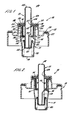
- a metering valve 10 for an aerosol container comprises the following main components:
- the valve housing 11 is of generally cylindrical configuration, closed at one end 18 and having an enlarged diameter portion 19 at its other, open, end which provides a seat for the metering chamber 16. Between the ends 18 and 19 of the valve housing 11, the housing comprises first and second cylindrical portions 20, 21 of differing diameter, these sections being joined by a frusto-conical portion 22. Orifices 23 formed in the cylindrical portion 21 adjacent the end portion 19 provide communication between the interior of the valve housing 11 and an aerosol container 17 to which the valve is attached, in use.
- the open end 19 of the valve housing fits within a central cylindrical portion 25 of the valve cup 13 and is retained in position by an annular indentation 26 in the valve cup.
- the valve cup 13 comprises a second cylindrical portion 28 of considerably greater diameter than the portion 25, the two cylindrical portions being joined by a radially extending portion 29 of generally S shaped cross-section.
- the exact shape of the portions 28, 29 of the valve cup will depend on the container to which the valve is to be attached.
- the configuration shown in the drawings is typical for attachment to an ordinary aerosol container but different configurations may be provided if the valve is to be attached to a bottle or a roll neck container.
- the valve cup 13 is attached to the aerosol container or bottle in known conventional manner, a gasket 27 being provided to form a seal between the valve cup 13 and the container.
- the metering chamber 16 is located within the valve housing 11 and co-axial therewith.
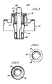
- the metering chamber 16 is formed from two components, inner and outer chamber components 30, 31 respectively.
- the outer chamber component 31 is a cylindrical member having an inturned portion 33 at one end and an outwardly turned annular flange 34 at the other end.
- the inner chamber portion 30 has an inwardly turned end 36 adjacent to end 33 of chamber portion 31 and, at its other end, an outwardly and upwardly turned portion 38.
- the portion 38 of chamber component 30 provides a seating for the first seal 14 which is clamped between the annular shoulder defined by the portion 38 and the upper end 39 of the valve cup.
- the chamber component 31 fits around the chamber component 30 as shown in Figures 7 to 3 and is retained in assembled, nested, relation therewith by its portion 34 being clamped between the underside of portion 38 of chamber component 30 and the annular shoulder defined by portion 19 of the valve cup 11.
- the second seal 15 of the valve is located between portions 33 and 36 of chamber components 31 and 30 respectively.
- portions 33 and 36 of chamber components 31, 30 are provided with castellations.
- portion 33 has four castelletions 41 while portion 36 has six castelletions 42.
- the number of castelletions provided in portion 33, 36 is not critical, the numbers of castelletions in the two portions should differ.
- the castelletions are provided for a purpose to be described below.
- the size of the metering chamber is defined by chamber component 30.
- the size of the chamber may therefore be varied by altering the shape of component 30. Conseauential alteration of the shape of component 31 will then also be reauired so that the components 30, 31 still fit together in nested relation. It will be appreciated that altering the size and shape of the sub-assembly of components 30,31 need not affect the other components in the valve or the assembly of the valve.
- the central portion of chamber component 30 may include a reduced diameter portion or its length may be altered while the end portions 36, 38 of chamber component 30 remain unaltered.
- valve body 11 may be of a larger diameter.
- the assembled metering chamber components and seal 15 have a central aperture 44 provided therein and aligned apertures 45, 46 are provided in the first seal 14 and the upper end 39 of the valve cup 13.
- the valve stem 12 is a sliding fit in these apertures.
- the valve stem 12 is a hollow generally cylindrical tube having an outlet orifice 48 at its upper end and an inlet aperture 49 formed in its side wall at the position shown in the drawings.
- the valve stem includes an enlarged diameter portion 50 which, in the position shown in Figure 1, seats on the first seal 14 and thereby defines the upper most position of the valve stem.
- the lower end of the valve stem is closed and includes an inverted wall portion 52 which extends from the lower end of the valve stem for approximately one third of its length to a position above the seal 15 when the valve is in its inoperative position shown in Figure 1.
- the inverted wall portion 52 defines a channel extending axially along the valve stem. The length of this channel may vary as the length of chamber component 30 is varied.
- a cup shaped member 55 fits around the lower end of the valve stem 12 and includes an outwardly turned portion 56 defining an annular shoulder which provides a seating for one end of a spring 60.
- the spring 60 urges the valve stem into its inoperative position as shown in Figure 1 and the other end of the spring 60 seats on the lower end wall of the valve housing 11.
- valve 10 With the exception of the first and second seals 14, 15 which are of a known rubber compound, and the gasket 27 which is also usually rubber, all the components of the valve 10 are formed from metal.
- the valve cup 13, and spring retaining cup 55 are of aluminium while the remaining components of the valve are of stainless steel.
- valve 10 The operation of the valve 10 is as follows.
- the valve is designed for use in an inverted position.
- references have been made to upper and lower ends of components and this describes the valve in the position shown in Figures 1 to 3 which is its normal upright position when it is attached to a can or bottle and that can or bottle is standing upright. This is the usual rest position.
- the valve is inverted in use, that is rotated through 180° from the position shown in Figures 1 to 3.
- FIG. 1 shows the valve in its inoperative position and imagining the valve to be inverted
- the contents of the container to which the valve is attached that is the product to be dispensed
- the product will flow through apertures 23 to fill the valve cup 11.
- the product will also flow via passage 52 into the metering chamber 16 and thereby fill the metering chamber.
- the product will not be released from the metering chamber because the first valve seal 14 is in sealing contact around the valve stem 12, and abutting the enlarged diameter portion 50.
- valve stem 12 When it is desired to dispense a metered dose of product through the valve 10, the valve stem 12 is depressed (that is moved downwardly with respect to the position shown in Figure 11 until the valve stem reaches the position shown in Figure 2 relative to the other components of the valve. In the position shown in Figure 2, the valve stem has reached a position where the passage 52 is no longer providing a flow path between the interior of the metering chamber 16 and the interior of the valve cup 11. As shown in Figure 2, the passage 52 is now below the second valve seal 15 which is now in sealing contact with the valve stem thereby isolating the metering chamber from the valve cup 11.
- valve stem Upon further depression of the valve stem, the stem moves to the position shown in Figure 3 relative to the other components of the valve. In this position, the valve stem is still in sealing contact with the lower valve seal 15 so that no product may enter the metering chamber 16. However, the inlet aperture 49 has now passed through the upper valve seal 14 so that the metering chamber is in communication with the interior of the valve stem and thence with the outlet aperture 48 from the valve stem. The metered dose of product contained in the metering chamber thereby passes out through the valve stem to be dispensed.
- the spring 60 returns the valve stem from the position shown in Figure 3 to the position shown in Figure 2 where the inlet aperture 49 is again closed off and thence to the position shown in Figure 1 where the metering chamber 16 is again in communication with the interior of the valve housing 11 and is thereby refilled with the product to be dispensed.
- valve 10 is designed to facilitate such a filling operation. It is usual for such a filling operation to be conducted by placing a filling head over the valve. The filling head depresses the valve stem and forces product and pressure medium through and around the valve stem and thence into the metering chamber.
- the castellations 41, 42 formed in the components 30, 31 of the metering chamber are so arranged that, during this filling operation, they allow the second valve seal 15 to deflect thereby allowing product and pressure medium to pass through the seal 15 and thence through the valve housing 11 and into the container to which the valve is attached. It will be appreciated that the differing number of castellations in the two chamber components 30, 31 ensures that the castellations will never all be axially aligned so that an adequate seating for the second valve seal 15 is provided while still allowing adequate deflection of the valve seal during the filling operation.
- valve described is intended for use in an inverted position, a similar valve may be provided for upright operation.
- the apertures 23 will not be provided in the valve cup 11 which instead will have an inlet aperture at its lower end and a dip tube connected to that inlet aperture will extend to a position adjacent the bottom of the container to which the valve is attached.
- the size of the metering chamber may be predetermined by substituting for the chamber components 30, 31 alternative appropriately shaped components.
- castellations formed on the chamber components 30,31 may be replaced by cut-outs of different shape around the periphery of the central aperture of those components.
Landscapes
- Chemical & Material Sciences (AREA)
- Dispersion Chemistry (AREA)
- Engineering & Computer Science (AREA)
- Mechanical Engineering (AREA)
- Containers And Packaging Bodies Having A Special Means To Remove Contents (AREA)
- Filling Or Discharging Of Gas Storage Vessels (AREA)
- Nozzles (AREA)
- Self-Closing Valves And Venting Or Aerating Valves (AREA)
- Reciprocating Pumps (AREA)
Priority Applications (1)
| Application Number | Priority Date | Filing Date | Title |
|---|---|---|---|
| AT86300860T ATE45551T1 (de) | 1985-02-12 | 1986-02-07 | Ventil fuer unter druck stehende abgabebehaelter. |
Applications Claiming Priority (2)
| Application Number | Priority Date | Filing Date | Title |
|---|---|---|---|
| GB858503553A GB8503553D0 (en) | 1985-02-12 | 1985-02-12 | Valves for pressurised dispensing containers |
| GB8503553 | 1985-02-12 |
Publications (3)
| Publication Number | Publication Date |
|---|---|
| EP0191614A2 true EP0191614A2 (de) | 1986-08-20 |
| EP0191614A3 EP0191614A3 (en) | 1988-01-07 |
| EP0191614B1 EP0191614B1 (de) | 1989-08-16 |
Family
ID=10574333
Family Applications (1)
| Application Number | Title | Priority Date | Filing Date |
|---|---|---|---|
| EP86300860A Expired EP0191614B1 (de) | 1985-02-12 | 1986-02-07 | Ventil für unter Druck stehende Abgabebehälter |
Country Status (11)
| Country | Link |
|---|---|
| US (1) | US4744495A (de) |
| EP (1) | EP0191614B1 (de) |
| JP (1) | JP2507312B2 (de) |
| AT (1) | ATE45551T1 (de) |
| AU (1) | AU583888B2 (de) |
| CA (1) | CA1253468A (de) |
| DE (1) | DE3665049D1 (de) |
| ES (1) | ES8701102A1 (de) |
| GB (1) | GB8503553D0 (de) |
| IE (1) | IE58294B1 (de) |
| ZA (1) | ZA86970B (de) |
Cited By (3)
| Publication number | Priority date | Publication date | Assignee | Title |
|---|---|---|---|---|
| GB2198117A (en) * | 1986-11-28 | 1988-06-08 | Glaxo Group Ltd | Aerosol metering valve assembly |
| WO1988007010A1 (en) * | 1987-03-13 | 1988-09-22 | Riker Laboratories, Inc. | Aerosol valve |
| US6032835A (en) * | 1993-01-19 | 2000-03-07 | Glaxo Group Ltd. | Aerosol dispenser and method |
Families Citing this family (41)
| Publication number | Priority date | Publication date | Assignee | Title |
|---|---|---|---|---|
| GB8720978D0 (en) * | 1987-09-07 | 1987-10-14 | Bespak Plc | Collapsible chamber metering valve |
| DE3802498A1 (de) * | 1988-01-28 | 1989-08-03 | Boehringer Ingelheim Kg | Vorrichtung zur erhoehung der dosierungssicherheit von aerosolpraeparaten auf suspensionsbasis |
| US4867352A (en) * | 1988-04-05 | 1989-09-19 | Philip Meshberg | Dispensing valve assembly for use with a pressurized container |
| US4953759A (en) * | 1989-04-14 | 1990-09-04 | Vernay Laboratories, Inc. | Metering valve for dispensing aerosols |
| US5370862A (en) * | 1990-06-13 | 1994-12-06 | Schwarz Pharma Ag | Pharmaceutical hydrophilic spray containing nitroglycerin for treating angina |
| US7278590B1 (en) | 1992-02-24 | 2007-10-09 | Homax Products, Inc. | Systems and methods for applying texture material to ceiling surfaces |
| US8028864B2 (en) | 1992-02-24 | 2011-10-04 | Homax Products, Inc. | Actuator systems and methods for aerosol wall texturing |
| US6883688B1 (en) | 1992-02-24 | 2005-04-26 | Homax Products, Inc. | Aerosol spray texturing systems and methods |
| JP3339900B2 (ja) * | 1993-03-01 | 2002-10-28 | 株式会社ダイゾー | 定量噴射型エアゾール容器 |
| US6152335A (en) * | 1993-03-12 | 2000-11-28 | Homax Products, Inc. | Aerosol spray texture apparatus for a particulate containing material |
| DE69701051T2 (de) * | 1993-04-30 | 2000-08-31 | Minnesota Mining And Mfg. Co., Saint Paul | Abdichtung an Aerosolbehältern |
| US5474758A (en) * | 1993-07-28 | 1995-12-12 | Minnesota Mining And Manufacturing Company | Seals for use in an aerosol delivery device |
| US5421492A (en) * | 1993-11-02 | 1995-06-06 | Glaxo Inc. | Metered aerosol dispensing apparatus and method of use thereof |
| US5551496A (en) * | 1995-01-11 | 1996-09-03 | Gray, Jr.; Hugh H. | Concealable wallet |
| US5921447A (en) * | 1997-02-13 | 1999-07-13 | Glaxo Wellcome Inc. | Flow-through metered aerosol dispensing apparatus and method of use thereof |
| GB9918626D0 (en) * | 1999-08-07 | 1999-10-13 | Glaxo Group Ltd | Valve |
| GB0025092D0 (en) * | 2000-10-13 | 2000-11-29 | Glaxo Group Ltd | Medicament dispenser |
| DE60205487T2 (de) * | 2001-06-22 | 2006-06-01 | 3M Innovative Properties Co., St. Paul | Verfahren zur verbesserung des durchflusses einer aerosolformulierung in einem dosierventil für einen dosierinhalator |
| US7500621B2 (en) | 2003-04-10 | 2009-03-10 | Homax Products, Inc. | Systems and methods for securing aerosol systems |
| FR2860502B1 (fr) * | 2003-10-07 | 2007-09-14 | Valois Sas | Valve doseuse et dispositif de distribution de produit fluide comportant une telle valve |
| US20050161531A1 (en) | 2004-01-28 | 2005-07-28 | Greer Lester R.Jr. | Texture material for covering a repaired portion of a textured surface |
| US7677420B1 (en) | 2004-07-02 | 2010-03-16 | Homax Products, Inc. | Aerosol spray texture apparatus for a particulate containing material |
| US7487893B1 (en) | 2004-10-08 | 2009-02-10 | Homax Products, Inc. | Aerosol systems and methods for dispensing texture material |
| GB2417480B (en) * | 2004-12-15 | 2006-08-02 | Bespak Plc | Improvements in or relating to valves |
| DE102005002444A1 (de) * | 2005-01-19 | 2006-07-27 | Wella Ag | Behälter mit einem Ventil |
| FR2888822B1 (fr) * | 2005-07-21 | 2010-04-02 | Valois Sas | Valve de distribution de produit fluide |
| GB2448294B (en) * | 2006-12-13 | 2009-04-08 | Bespak Plc | Metering valve and dispensing apparatus |
| US8344056B1 (en) | 2007-04-04 | 2013-01-01 | Homax Products, Inc. | Aerosol dispensing systems, methods, and compositions for repairing interior structure surfaces |
| US8580349B1 (en) | 2007-04-05 | 2013-11-12 | Homax Products, Inc. | Pigmented spray texture material compositions, systems, and methods |
| US9382060B1 (en) | 2007-04-05 | 2016-07-05 | Homax Products, Inc. | Spray texture material compositions, systems, and methods with accelerated dry times |
| FR2917073B1 (fr) * | 2007-06-11 | 2012-10-05 | Valois Sas | Valve de distribution de produit fluide et dispositif de distribution de produit fluide comportant une telle valve |
| FR2924101B1 (fr) * | 2007-11-26 | 2009-12-04 | Valois Sas | Valve amelioree |
| FR2971772B1 (fr) * | 2011-02-17 | 2013-03-22 | Valois Sas | Dispositif de distribution de produit fluide. |
| US9248457B2 (en) | 2011-07-29 | 2016-02-02 | Homax Products, Inc. | Systems and methods for dispensing texture material using dual flow adjustment |
| US9156042B2 (en) | 2011-07-29 | 2015-10-13 | Homax Products, Inc. | Systems and methods for dispensing texture material using dual flow adjustment |
| US9156602B1 (en) | 2012-05-17 | 2015-10-13 | Homax Products, Inc. | Actuators for dispensers for texture material |
| US9435120B2 (en) | 2013-03-13 | 2016-09-06 | Homax Products, Inc. | Acoustic ceiling popcorn texture materials, systems, and methods |
| CA2859537C (en) | 2013-08-19 | 2019-10-29 | Homax Products, Inc. | Ceiling texture materials, systems, and methods |
| USD787326S1 (en) | 2014-12-09 | 2017-05-23 | Ppg Architectural Finishes, Inc. | Cap with actuator |
| ES2913089T3 (es) * | 2017-02-20 | 2022-05-31 | Presspart Gmbh & Co Kg | Inhalador dosificador |
| CN108452409B (zh) * | 2017-02-20 | 2022-04-01 | 普莱斯博有限两合公司 | 定量吸入器 |
Family Cites Families (10)
| Publication number | Priority date | Publication date | Assignee | Title |
|---|---|---|---|---|
| DE1033147B (de) * | 1955-11-21 | 1958-06-26 | Wilhelm Waldherr | Dosierventil mit Spruehkopf fuer Spruehdosen oder Flaschen |
| NL257608A (de) * | 1959-11-05 | |||
| US3135437A (en) * | 1961-04-13 | 1964-06-02 | Sterling Drug Inc | Valve constructions for aerosol containers |
| DE1400707A1 (de) * | 1963-05-29 | 1968-10-17 | Abplanalp Robert H | Fuelleinrichtung fuer Aerosolbehaelter mit einer ein Abgabeventil tragenden Verschlusskappe |
| GB1201918A (en) * | 1966-12-21 | 1970-08-12 | Bespak Industries Ltd | Improvements in or relating to valves for pressurised dispensers |
| US3547317A (en) * | 1968-07-15 | 1970-12-15 | Green Edward | Valve assembly for dispensing metered amounts of pressurized product |
| BE757237A (fr) * | 1969-10-13 | 1971-03-16 | Neotechnic Eng Ltd | Perfectionnements relatifs aux assemblages de soupape pour recipients aaerosol |
| US3813013A (en) * | 1972-06-27 | 1974-05-28 | Risdon Mfg Co | Aerosol metering valve |
| GB2086845B (en) * | 1977-09-22 | 1982-12-08 | Glaxo Group Ltd | Metering valve |
| FR2502732B1 (fr) * | 1981-03-30 | 1985-08-30 | Valois Sa | Valve doseuse a position inversee pour recipient d'aerosol |
-
1985
- 1985-02-12 GB GB858503553A patent/GB8503553D0/en active Pending
-
1986
- 1986-02-07 EP EP86300860A patent/EP0191614B1/de not_active Expired
- 1986-02-07 AT AT86300860T patent/ATE45551T1/de not_active IP Right Cessation
- 1986-02-07 DE DE8686300860T patent/DE3665049D1/de not_active Expired
- 1986-02-10 ZA ZA86970A patent/ZA86970B/xx unknown
- 1986-02-11 ES ES551842A patent/ES8701102A1/es not_active Expired
- 1986-02-11 AU AU53375/86A patent/AU583888B2/en not_active Ceased
- 1986-02-11 IE IE38986A patent/IE58294B1/en not_active IP Right Cessation
- 1986-02-11 CA CA000501558A patent/CA1253468A/en not_active Expired
- 1986-02-11 US US06/828,379 patent/US4744495A/en not_active Expired - Fee Related
- 1986-02-12 JP JP61029834A patent/JP2507312B2/ja not_active Expired - Lifetime
Cited By (6)
| Publication number | Priority date | Publication date | Assignee | Title |
|---|---|---|---|---|
| GB2198117A (en) * | 1986-11-28 | 1988-06-08 | Glaxo Group Ltd | Aerosol metering valve assembly |
| FR2611381A1 (fr) * | 1986-11-28 | 1988-09-02 | Glaxo Group Ltd | Valve servant a delivrer des doses mesurees et recipient equipe |
| BE1001726A5 (fr) * | 1986-11-28 | 1990-02-20 | Glaxo Group Ltd | Ensemble de valve. |
| GB2198117B (en) * | 1986-11-28 | 1990-03-28 | Glaxo Group Ltd | Valve assembly |
| WO1988007010A1 (en) * | 1987-03-13 | 1988-09-22 | Riker Laboratories, Inc. | Aerosol valve |
| US6032835A (en) * | 1993-01-19 | 2000-03-07 | Glaxo Group Ltd. | Aerosol dispenser and method |
Also Published As
| Publication number | Publication date |
|---|---|
| EP0191614A3 (en) | 1988-01-07 |
| AU583888B2 (en) | 1989-05-11 |
| US4744495A (en) | 1988-05-17 |
| ES8701102A1 (es) | 1986-11-16 |
| ATE45551T1 (de) | 1989-09-15 |
| ZA86970B (en) | 1987-09-30 |
| IE58294B1 (en) | 1993-08-25 |
| JP2507312B2 (ja) | 1996-06-12 |
| IE860389L (en) | 1986-08-12 |
| GB8503553D0 (en) | 1985-03-13 |
| AU5337586A (en) | 1986-08-21 |
| JPS61190467A (ja) | 1986-08-25 |
| CA1253468A (en) | 1989-05-02 |
| ES551842A0 (es) | 1986-11-16 |
| EP0191614B1 (de) | 1989-08-16 |
| DE3665049D1 (en) | 1989-09-21 |
Similar Documents
| Publication | Publication Date | Title |
|---|---|---|
| US4744495A (en) | Valve for pressurized dispensing containers | |
| EP1923139B1 (de) | Aerosolspender | |
| US5687884A (en) | Metering device for dispensing constant unit doses | |
| US2863699A (en) | Resilient valve mounting assembly | |
| US4756347A (en) | Filling and dispensing valve, adapter and package | |
| US2631814A (en) | Valve mechanism for dispensing gases and liquids under pressure | |
| US5632421A (en) | Aerosol metering valves | |
| US6923342B2 (en) | Systems for dispensing multi-component products | |
| EP0702652B1 (de) | Aerosolventil zur dosierten abgabe | |
| US3451596A (en) | Integral plug valve assembly for dispenser of products in the fluid state | |
| JP2995510B2 (ja) | 気体圧力を受けている流体を入れた容器用の 制御弁及びこの種の弁を備えた容器 | |
| AU2001293171A1 (en) | Aerosol spray dispenser | |
| US3682355A (en) | Pressure actuated valve | |
| EP3536633B1 (de) | Mehrteiliger ventilschaft für aerosole | |
| US3854636A (en) | Aerosol valve for low delivery rate | |
| US3651997A (en) | Combined pressure filling and dispensing control valve for aerosol containers | |
| US4867352A (en) | Dispensing valve assembly for use with a pressurized container | |
| EP0567348B1 (de) | Dosierventil für Aerosolbehälter | |
| GB2198117A (en) | Aerosol metering valve assembly | |
| EP0125865B1 (de) | Ventil für Aerosolbehälter | |
| EP0774423A1 (de) | Ventildichtung für unter Druck stehende Abgabebehälter | |
| US4966313A (en) | Device enabling a spray valve to be used in any position | |
| GB2209805A (en) | Dispensing valve assembly | |
| US3506160A (en) | Self-venting multiple product mixing valve construction | |
| JPS62208380A (ja) | バルブアセンブリおよびバルブアセンブリに使用するアダプタ |
Legal Events
| Date | Code | Title | Description |
|---|---|---|---|
| PUAI | Public reference made under article 153(3) epc to a published international application that has entered the european phase |
Free format text: ORIGINAL CODE: 0009012 |
|
| AK | Designated contracting states |
Kind code of ref document: A2 Designated state(s): AT BE CH DE FR GB IT LI LU NL SE |
|
| 17P | Request for examination filed |
Effective date: 19870203 |
|
| PUAL | Search report despatched |
Free format text: ORIGINAL CODE: 0009013 |
|
| AK | Designated contracting states |
Kind code of ref document: A3 Designated state(s): AT BE CH DE FR GB IT LI LU NL SE |
|
| 17Q | First examination report despatched |
Effective date: 19880926 |
|
| GRAA | (expected) grant |
Free format text: ORIGINAL CODE: 0009210 |
|
| AK | Designated contracting states |
Kind code of ref document: B1 Designated state(s): AT BE CH DE FR GB IT LI LU NL SE |
|
| REF | Corresponds to: |
Ref document number: 45551 Country of ref document: AT Date of ref document: 19890915 Kind code of ref document: T |
|
| REF | Corresponds to: |
Ref document number: 3665049 Country of ref document: DE Date of ref document: 19890921 |
|
| ITF | It: translation for a ep patent filed | ||
| ET | Fr: translation filed | ||
| PLBE | No opposition filed within time limit |
Free format text: ORIGINAL CODE: 0009261 |
|
| STAA | Information on the status of an ep patent application or granted ep patent |
Free format text: STATUS: NO OPPOSITION FILED WITHIN TIME LIMIT |
|
| 26N | No opposition filed | ||
| ITTA | It: last paid annual fee | ||
| PGFP | Annual fee paid to national office [announced via postgrant information from national office to epo] |
Ref country code: LU Payment date: 19931116 Year of fee payment: 9 |
|
| PGFP | Annual fee paid to national office [announced via postgrant information from national office to epo] |
Ref country code: BE Payment date: 19931206 Year of fee payment: 9 |
|
| PGFP | Annual fee paid to national office [announced via postgrant information from national office to epo] |
Ref country code: SE Payment date: 19931208 Year of fee payment: 9 |
|
| PGFP | Annual fee paid to national office [announced via postgrant information from national office to epo] |
Ref country code: CH Payment date: 19931223 Year of fee payment: 9 |
|
| EPTA | Lu: last paid annual fee | ||
| PGFP | Annual fee paid to national office [announced via postgrant information from national office to epo] |
Ref country code: AT Payment date: 19940225 Year of fee payment: 9 |
|
| PGFP | Annual fee paid to national office [announced via postgrant information from national office to epo] |
Ref country code: NL Payment date: 19940228 Year of fee payment: 9 |
|
| EAL | Se: european patent in force in sweden |
Ref document number: 86300860.3 |
|
| PG25 | Lapsed in a contracting state [announced via postgrant information from national office to epo] |
Ref country code: LU Free format text: LAPSE BECAUSE OF NON-PAYMENT OF DUE FEES Effective date: 19950207 Ref country code: AT Effective date: 19950207 |
|
| PG25 | Lapsed in a contracting state [announced via postgrant information from national office to epo] |
Ref country code: SE Effective date: 19950208 |
|
| PG25 | Lapsed in a contracting state [announced via postgrant information from national office to epo] |
Ref country code: LI Effective date: 19950228 Ref country code: CH Effective date: 19950228 Ref country code: BE Effective date: 19950228 |
|
| BERE | Be: lapsed |
Owner name: BESPAK P.L.C. Effective date: 19950228 |
|
| PG25 | Lapsed in a contracting state [announced via postgrant information from national office to epo] |
Ref country code: NL Effective date: 19950901 |
|
| NLV4 | Nl: lapsed or anulled due to non-payment of the annual fee |
Effective date: 19950901 |
|
| EUG | Se: european patent has lapsed |
Ref document number: 86300860.3 |
|
| PGFP | Annual fee paid to national office [announced via postgrant information from national office to epo] |
Ref country code: DE Payment date: 19970228 Year of fee payment: 12 |
|
| PGFP | Annual fee paid to national office [announced via postgrant information from national office to epo] |
Ref country code: FR Payment date: 19971128 Year of fee payment: 13 |
|
| PG25 | Lapsed in a contracting state [announced via postgrant information from national office to epo] |
Ref country code: DE Free format text: LAPSE BECAUSE OF NON-PAYMENT OF DUE FEES Effective date: 19981103 |
|
| PGFP | Annual fee paid to national office [announced via postgrant information from national office to epo] |
Ref country code: GB Payment date: 19990129 Year of fee payment: 14 |
|
| PG25 | Lapsed in a contracting state [announced via postgrant information from national office to epo] |
Ref country code: FR Free format text: LAPSE BECAUSE OF NON-PAYMENT OF DUE FEES Effective date: 19991029 |
|
| REG | Reference to a national code |
Ref country code: FR Ref legal event code: ST |
|
| PG25 | Lapsed in a contracting state [announced via postgrant information from national office to epo] |
Ref country code: GB Free format text: LAPSE BECAUSE OF NON-PAYMENT OF DUE FEES Effective date: 20000207 |
|
| GBPC | Gb: european patent ceased through non-payment of renewal fee |
Effective date: 20000207 |
|
| PG25 | Lapsed in a contracting state [announced via postgrant information from national office to epo] |
Ref country code: IT Free format text: LAPSE BECAUSE OF NON-PAYMENT OF DUE FEES;WARNING: LAPSES OF ITALIAN PATENTS WITH EFFECTIVE DATE BEFORE 2007 MAY HAVE OCCURRED AT ANY TIME BEFORE 2007. THE CORRECT EFFECTIVE DATE MAY BE DIFFERENT FROM THE ONE RECORDED. Effective date: 20050207 |