EP0191696B1 - Dispositif de projection de particules solides pour broyeur centrifuge sous vide - Google Patents
Dispositif de projection de particules solides pour broyeur centrifuge sous vide Download PDFInfo
- Publication number
- EP0191696B1 EP0191696B1 EP86400256A EP86400256A EP0191696B1 EP 0191696 B1 EP0191696 B1 EP 0191696B1 EP 86400256 A EP86400256 A EP 86400256A EP 86400256 A EP86400256 A EP 86400256A EP 0191696 B1 EP0191696 B1 EP 0191696B1
- Authority
- EP
- European Patent Office
- Prior art keywords
- wheel
- curve
- particles
- channels
- friction
- Prior art date
- Legal status (The legal status is an assumption and is not a legal conclusion. Google has not performed a legal analysis and makes no representation as to the accuracy of the status listed.)
- Expired
Links
Images

Classifications
-
- B—PERFORMING OPERATIONS; TRANSPORTING
- B02—CRUSHING, PULVERISING, OR DISINTEGRATING; PREPARATORY TREATMENT OF GRAIN FOR MILLING
- B02C—CRUSHING, PULVERISING, OR DISINTEGRATING IN GENERAL; MILLING GRAIN
- B02C13/00—Disintegrating by mills having rotary beater elements ; Hammer mills
- B02C13/14—Disintegrating by mills having rotary beater elements ; Hammer mills with vertical rotor shaft, e.g. combined with sifting devices
- B02C13/18—Disintegrating by mills having rotary beater elements ; Hammer mills with vertical rotor shaft, e.g. combined with sifting devices with beaters rigidly connected to the rotor
- B02C13/1807—Disintegrating by mills having rotary beater elements ; Hammer mills with vertical rotor shaft, e.g. combined with sifting devices with beaters rigidly connected to the rotor the material to be crushed being thrown against an anvil or impact plate
- B02C13/1835—Disintegrating by mills having rotary beater elements ; Hammer mills with vertical rotor shaft, e.g. combined with sifting devices with beaters rigidly connected to the rotor the material to be crushed being thrown against an anvil or impact plate by means of beater or impeller elements fixed in between an upper and lower rotor disc
- B02C13/1842—Disintegrating by mills having rotary beater elements ; Hammer mills with vertical rotor shaft, e.g. combined with sifting devices with beaters rigidly connected to the rotor the material to be crushed being thrown against an anvil or impact plate by means of beater or impeller elements fixed in between an upper and lower rotor disc with dead bed protected beater or impeller elements
Definitions
- the present invention relates to a device for projecting solid particles for a vacuum mill in which the particles to be ground are projected by centrifugal force onto an impact surface disposed inside a vacuum enclosure, in accordance with the preamble of the claim 1 FR-A-2 201 928).
- a vacuum crusher comprises a closed enclosure that is resistant to pressure and evacuated and at the top of which is placed a distributing wheel driven in rotation at high speed.
- the wheel is provided in its axis with a central feed chamber provided at its upper part with an axial orifice formed at the bottom of a hopper supplied with material to be ground by means of a metering device, for example screw, placed at the outlet of a supply chamber forming an airlock and which makes it possible to introduce the material into the vacuum enclosure.
- the distributing wheel is also provided with a plurality of projection channels, the axes of which are centered in a median plane perpendicular to the axis and which open inwards into the supply chamber and outwards on the periphery of the wheel.
- the material introduced by the metering device into the central feeding chamber is therefore driven by centrifugal effect in the channels and projected at the outlet of these on a set of plates forming targets and which are placed all around the wheel. , along the side wall of the enclosure.
- the lower part of the latter is in the form of a hopper and collects the fine powder formed by the bursting of the grains of material thus projected onto the targets by the channels of the wheel.
- a radial and tangential acceleration is created inside the channels, making it possible to obtain the desired speed at the outlet.
- a contact effect between the particles and the wheel which depends on the speed of rotation and consequently a phenomenon of wear of the channels, in particular at the outlet of the wheel.
- This abrasion phenomenon depends on the physical properties of the particles, but is always very important as soon as the ejection speed also becomes high, having regard to the high value of the particle-wheel contact effect and the relative speed of displacement of particles in the channels.
- the subject of the invention is a new embodiment of a grinder wheel which makes it possible to remedy these drawbacks, by reducing the speed of movement of the particles in the projection channels while maintaining the same ejection speed.
- the guide face of the particles in each channel has a positive, continuous curve, that is to say a curve winding in the same direction of rotation of the distributing wheel, and whose route judiciously calculated , as a function of the coefficients of friction of the materials in contact, achieves the attachment on this curve of a stable layer of self-protection constituted by the particles themselves, with automatic regeneration of said layer at the same time as its wear.
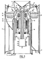
- a cylindrical enclosure 1 with a vertical axis at the upper part of which is disposed a vertical duct of large section 2 having a branch on which is fixed a duct 3 connected to a vacuum pump not shown.
- a duct 3 connected to a vacuum pump not shown.
- hoppers 4 and 5 Inside the duct 2 are arranged hoppers 4 and 5.
- the hopper 5 is connected to a vibrator 6.
- a hopper 7 secured to a wheel 20 constituting the upper part of the rotor. This wheel is pierced with several radial direction channels such as 21 and 22 regularly distributed.
- a target 8 is arranged, the impact surface of which is covered with a material resistant to wear and impact.
- deflectors 9 fixed to a hopper which can be vibrating 10 whose role is to collect the crushed pulverulent material. to direct it towards the outlet 11 connected to a set of vacuum locks allowing the product to flow without breaking the vacuum in the enclosure.
- the wheel 20 constituting the upper part of the rotor of the mill is secured to an elongated cylindrical tubular shaft 12.
- This shaft 12, driven by a motor 13, is guided and supported by a set of bearings and stops 14.
- the motor 13 makes it possible to drive the wheel 20 in rotation at very high speeds.
- Fig. 2 there is shown on a larger scale the dispensing wheel 20 inside which are formed a supply chamber 23 and two channels 21 and 22 opening at their ends inwards into the supply chamber 23 and towards the outside on the periphery of the wheel by evacuation orifices 24 and 25.
- the granular material penetrates into the feed chamber 23 and is projected outwards, by centrifugal effect passing through the channels 21 and 22.
- the particles thus projected by the channels strike the target 8 and are reduced to a fine powder. .
- the granular materials for example cement or pulverized coal, treated in centrifugal mills being fairly abrasive, we find in mills of this type used until now, a fairly rapid wear of the internal side wall of the projection channels, and in particular of the peripheral outlet orifice.
- the invention makes it possible to avoid this wear phenomenon by giving the distribution channels a particular and determined curve.
- the friction face of each channel, on which the grains are projected has a positive curve A, that is to say a curve which winds in the same direction m as the rotation of the distributing wheel 20 .
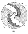
- This curve A the layout of which is judiciously calculated, as a function of the coefficients of friction of the materials in contact, that is to say as a function of the material constituting the distributing wheel and of the particles to be projected, allows the attachment to this curve A a stable layer 30 (FIG. 3) constituted by the particles themselves, thus providing effective protection of the distributor wheel.
- the distributing wheel 20 must rotate at a greater or lesser speed. But in all cases we will obtain the creation of a protective mattress, because the plating of the particles is independent of the speed of rotation of the wheel.
- Self-protection of the channels is therefore carried out by the product itself, which avoids any abrasion phenomenon, while maintaining a sufficient speed of rotation of the distributing wheel to obtain the desired particle size.
- a substantially flat or disk-shaped wheel it is also possible to use, for example, a hemispherical bowl, but the principle of tracing the channels remains the same to obtain the attachment of a film of particles to spray which serves as a protective layer for the channels and prevents abrasion by particles.
- the number of ejection channels depends on the flow to be produced and on the diameter of the distributor wheel.
Landscapes
- Engineering & Computer Science (AREA)
- Food Science & Technology (AREA)
- Crushing And Grinding (AREA)
- Crushing And Pulverization Processes (AREA)
- Manufacture Of Metal Powder And Suspensions Thereof (AREA)
- Glanulating (AREA)
- Disintegrating Or Milling (AREA)
Description
- La présente invention concerne un dispositif de projection de particules solides pour un broyeur sous vide dans lequel les particules à broyer sont projetées par force centrifuge sur une surface d'impact disposée à l'intérieur d'une enceinte sous vide, conformément au préambule de la revendication 1 FR-A-2 201 928).
- On sait que ce type de broyeur utilise la force centrifuge pour projeter les matériaux à broyer sur des cibles à des vitesses très élevées, l'ensemble du dispositif étant disposé sous vide afin d'éviter le freinage des particules projetées par la résistance de l'air.
- Un broyeur sous vide comprend une enceinte fermée résistant à la pression et mise sous vide et à la partie supérieure de laquelle est placée une roue distributrice entraînée en rotation à grande vitesse. La roue est munie dans son axe d'une chambre centrale d'alimentation munie à sa partie supérieure d'un orifice axial ménagé au fond d'une trémie alimentée en matière à broyer par l'intermédiaire d'un dispositif de dosage, par exemple à vis, placé au débouché d'une chambre d'alimentation formant sas et qui permet d'introduire la matière dans l'enceinte sous vide.
- La roue distributrice est munie d'autre part d'une pluralité de canaux de projection dont les axes sont centrés dans un plan médian perpendiculaire à l'axe et qui débouchent vers l'intérieur dans la chambre d'alimentation et vers l'extérieur sur la périphérie de la roue. La matière introduite par le dispositif de dosage dans la chambre centrale d'alimentation est donc entraînée par effet centrifuge dans les canaux et projetée à la sortie de ceux-ci sur un ensemble de plaques formant des cibles et qui sont placées tout autour de la roue, le long de la paroi latérale de l'enceinte. La partie inférieure de celle-ci est en forme de trémie et récupère la poudre fine formée par l'éclatement des grains de matière ainsi projetés sur les cibles par les canaux de la roue.
- Si la roue distributrice tourne à une vitesse suffisante, on crée donc à l'intérieur des canaux, une accélération radiale et tangentielle, permettant d'obtenir à la sortie la vitesse désirée. Il se produit, à l'intérieur de ces canaux, un effet de contact entre les particules et la roue qui dépend de la vitesse de rotation et par conséquent un phénomène d'usure des canaux, notamment à la sortie de la roue. Ce phénomène d'abrasion dépend des propriétés physiques des particules, mais est toujours très important dès que la vitesse d'éjection devient elle aussi importante, eu égard à la valeur élevée de l'effet de contact particules-roue et de la vitesse relative de déplacement des particules dans les canaux.
- Jusqu'à présent, les moyens de protection employés et notamment les traitements de surface n'ont pas permis de donner à la roue distributrice une résistance suffisante et l'on est amené à changer la roue distributrice assez souvent, ce qui est évidemment onéreux, chaque roue devant être réalisée et usinée avec une grande précision en raison de sa très grande vitesse de rotation qui la soumet à des efforts importants. Par ailleurs, pour effectuer ces opérations, on est amené à arrêter le broyeur, ce qui est incompatible avec une marche industrielle dans des domaines où une production continue est demandée tels que la cimenterie ou le broyage des minerais.
- L'invention a pour objet un nouveau mode de réalisation d'une roue de broyeur permettant de remédier à ces inconvénients, en réduisant la vitesse de déplacement des particules dans les canaux de projection tout en conservant la même vitesse d'éjection.
- Suivant l'invention, la face de guidage des particules dans chaque canal a une courbe positive, continue, c'est-à-dire une courbe s'enroulant dans le même sens de rotation de la roue distributrice, et dont le tracé judicieusement calculé, en fonction des coefficients de frottement des matériaux en contact, réalise l'accrochage sur cette courbe d'une couche stable d'autoprotection constituée par les particules elles-mêmes, avec régénération automatique de ladite couche en même temps que son usure.
- L'invention sera mieux comprise à l'aide de la description suivante d'un exemple de réalisation en référence aux dessins annexés qui représentent:
- - Fig. 1 une vue schématique en coupe dans un plan vertical de l'ensemble d'un broyeur utilisant une roue distributrice selon l'invention,
- - Fig. 2 une vue en coupe selon la ligne AA de la Fig. 1,
- - Fig. 3 une vue identique à la Fig. 2 montrant le trajet suivi par les particules dans la roue distributrice pendant le fonctionnement du broyeur.
- Sur la Fig. 1, on voit une enceinte 1 cylindrique à axe vertical à la partie supérieure de laquelle est disposé un conduit vertical de grande section 2 présentant une dérivation sur laquelle est fixé un conduit 3 relié à une pompe à vide non représentée. A l'intérieur du conduit 2 sont disposées des trémies 4 et 5. La trémie 5 est reliée à un vibreur 6.
- En-dessous de la trémie vibrante 5 est disposée une trémie 7 solidaire d'une roue 20 constituant la partie supérieure du rotor. Cette roue est percée de plusieurs canaux de direction radiale tels que 21 et 22 régulièrement répartis.
- Dans le prolongement de ces canaux et tout autour de l'enceinte, est disposée une cible 8 dont la surface d'impact est recouverte d'une matière résistant à l'usure et aux chocs.
- On peut déterminer entre la surface périphérique externe de la roue 20 et la cible 8 une zone d'espace dans laquelle vont être projetées les particules à broyer. En-dessous de cette zone d'espace sont disposés des déflecteurs 9 fixés à une trémie qui peut être vibrante 10 dont le rôle est de recueillir la matière pulvérulente broyée pour la diriger vers la sortie 11 reliée à un jeu de sas sous vide permettant l'écoulement du produit sans casser le vide dans l'enceinte.
- La roue 20 constituant la partie supérieure du rotor du broyeur est solidaire d'un arbre allongé cylindrique 12 tubulaire. Cet arbre 12, entraîné par un moteur 13, est guidé et supporté par un ensemble de paliers et de butées 14.
- Le moteur 13 permet d'entraîner la roue 20 en rotation à de très grandes vitesses.
- Sur la Fig. 2, on a représenté à plus grande échelle la roue distributrice 20 à l'intérieur de laquelle sont ménagés une chambre d'alimentation 23 et deux canaux 21 et 22 débouchant à leurs extrémités vers l'intérieur dans la chambre d'alimentation 23 et vers l'extérieur sur la périphérie de la roue par des orifices d'évacuation 24 et 25.
- La matière en grains pénètre dans la chambre d'alimentation 23 et est projetée vers l'extérieur, par effet centrifuge en passant par les canaux 21 et 22. Les particules ainsi projetées par les canaux frappent la cible 8 et sont réduits en une poudre fine.
- Les matières granulaires, par exemple du ciment ou du charbon pulvérisé, traitées dans les broyeurs centrifuges étant assez abrasives, on constate dans les broyeurs de ce type utilisés jusqu'à présent, une usure assez rapide de la paroi latérale interne des canaux de projection, et notamment de l'orifice de sortie périphérique.
- L'invention permet d éviter ce phénomène d'usure en donnant aux canaux de distribution une courbe particulière et déterminée.
- Pour celà, la face de frottement de chaque canal, sur laquelle sont projetés les grains, a une courbe A positive, c'est-à-dire une courbe qui s'enroule dans le même sens m que la rotation de la roue distributrice 20.
- Cette courbe A dont le tracé est judicieusement calculé, en fonction des coefficients de frottement des matériaux en contact c'est-à-dire en fonction du matériau constitutif de la roue distributrice et des particules à projeter, permet l'accrochage sur cette courbe A d'une couche stable 30 (Fig. 3) constituée par les particules elles-mêmes, réalisant ainsi une protection efficace de la roue distributrice.
- En se reportant a la Fig. 3, la détermination de la courbe A formant la face d appui de chaque canal s'effectue de la façon suivante:
- En considérant une particule en un point M, point de contact entre ladite particule et la face d'appui du canal, on voit que l'effort de contact N en ce point M peut être dirigé suivant le rayon vecteur OX si:

- Ψ étant l'angle fait par la tangente à la courbe et le rayon vecteur au point M considéré,
- ϕ étant l'angle dont la tangente est égale au coefficient de frottement, donc dépendant des matériaux en contact.
- Pour toute courbe définie mathématiquement en coordonnées polaires, on a:

- p = rayon au point M donné,
- p = f (β) = fonction de l'angle β,
- β étant l'angle entre l'axe origine et le rayon vecteur au moint M.
- Connaissant l'équation de la courbe, on peut donc calculer tg Ψ pour chacun de ses points.
- Par conséquent, lorsque ψ + ϕ = n /2 = 90°, l'effort de contact N passe par 0, centre de la roue distributrice sur l'axe de rotation. Dans ce cas, toute particule placée en un point M ayant un coefficient de frottement avec le matériau de la roue égal à tg ϕ reste immobile. Il existe donc une courbe que l'on peut appeler "courbe limite de blocage" telle que l'on ait en chaque point Ψ + ϕ= π /2, courbe sur laquelle les particules restent immobiles.
- Ainsi, si l'on réalise sur la roue distributrice 20 des canaux 21 et 22, dont la face d'appui ou de frottement est tracée suivant la courbe A pour que l'on ait en tout point Ψ + ϕ > π/2 de telle sorte que toute particule arrivant sur la face du canal tracé suivant cette courbe sera bloquée.
- Par conséquent. il va donc se produire un entassement 30 de particules jusqu'à ce que cet entassement dessine une courbe B (Fig. 3) telle que l'on ait, pour cette courbe
-

- Par ce moyen, on va donc maintenir sur la face de frottement de chaque canal une couche de pellicules immobiles dont l'épaisseur est fonction des courbes A et B. Cette couche fixe constitue donc une véritable protection de la roue distributrice.
- Après formation de cette couche protectrice, c'est-à-dire après avoir atteint la courbe B, les particules amenées par la chambre d'alimentation 23 de la roue distributrice 20 vont entrer en mouvement et glisser sur le matelas de particules prisonnières entre les courbes A et B, avec régénération automatique du matelas en même temps que son usure, et éjection des particules à la vitesse souhaitée par les orifices 24 et 25.
- En connaissant les caractéristiques du matériau à projeter et celles du matériau constitutif de la roue distributrice, on peut facilement déterminer le coefficient de frottement des particules avec le matériau choisi pour la réalisation de la roue. De même, si l'on connaît le coefficient de frottement du matériau à projeter sur lui-même, on peut alors aisément prévoir la courbe limite B.
- Dans le cas où le coefficient de frottement du matérial à projeter sur lui-même est supérieur au coefficient de frottement du matériau à projeter sur le matériau constituant la roue, c'est le centre de gravité de la pellicule protectrice qui devra être sur une courbe tel que Ψ + <p > 90°. Le fond du canal, face d'accrochage de cette pellicule devra donc être calculé en conséquence.
- En fonction de la nature du produit à projeter et de la granulométrie du produit que l'on désire obtenir, la roue distributrice 20 doit tourner à une vitesse plus ou moins grande. Mais dans tous les cas on obtiendra la création d'un matelas protecteur, car le placage des particules est indépendant de la vitesse de rotation de la roue.
- On réalise donc une auto-protection des canaux par le produit lui-même, ce qui évite tout phénomène d'abrasion, tout en conservant une vitesse de rotation suffisante de la roue distributrice pour obtenir la granulométrie désirée.
- L'invention ne se limite pas au mode de réalisation qui vient d'être décrit d'autres perfectionnements et des variantes peuvent être imaginés en restant dans le cadre de la protection revendiquée.
- En effet, au lieu d'utiliser une roue sensiblement plate ou en forme de disque, on peut également utiliser par exemple un bol hémisphérique, mais le principe de tracé des canaux reste le même pour obtenir l'accrochage d'une pellicule de particules à projeter qui sert de couche protectrice des canaux et évite l'abrasion par les particules. Par ailleurs, le nombre de canaux d'éjection dépend du débit à réaliser et du diamètre de la roue distributrice.
Claims (4)

Priority Applications (1)
| Application Number | Priority Date | Filing Date | Title |
|---|---|---|---|
| AT86400256T ATE46830T1 (de) | 1985-02-15 | 1986-02-06 | Festpartikel-schleudervorrichtung fuer zentrifugalzerkleinerer im vakuum. |
Applications Claiming Priority (2)
| Application Number | Priority Date | Filing Date | Title |
|---|---|---|---|
| FR8502234A FR2577445B1 (fr) | 1985-02-15 | 1985-02-15 | Dispositif de projection de particules solides pour broyeur centrifuge sous vide |
| FR8502234 | 1985-02-15 |
Publications (3)
| Publication Number | Publication Date |
|---|---|
| EP0191696A2 EP0191696A2 (fr) | 1986-08-20 |
| EP0191696A3 EP0191696A3 (en) | 1987-12-23 |
| EP0191696B1 true EP0191696B1 (fr) | 1989-10-04 |
Family
ID=9316334
Family Applications (1)
| Application Number | Title | Priority Date | Filing Date |
|---|---|---|---|
| EP86400256A Expired EP0191696B1 (fr) | 1985-02-15 | 1986-02-06 | Dispositif de projection de particules solides pour broyeur centrifuge sous vide |
Country Status (9)
| Country | Link |
|---|---|
| US (1) | US4682739A (fr) |
| EP (1) | EP0191696B1 (fr) |
| CN (1) | CN86100993B (fr) |
| AT (1) | ATE46830T1 (fr) |
| AU (1) | AU583088B2 (fr) |
| CA (1) | CA1243992A (fr) |
| DE (1) | DE3665990D1 (fr) |
| FR (1) | FR2577445B1 (fr) |
| ZA (1) | ZA86660B (fr) |
Families Citing this family (9)
| Publication number | Priority date | Publication date | Assignee | Title |
|---|---|---|---|---|
| FR2594048B1 (fr) * | 1986-02-10 | 1988-05-27 | Framatome Sa | Roue de broyeur a projection sous vide. |
| FR2628007B1 (fr) * | 1988-03-07 | 1993-09-17 | Electricite De France | Broyeur a percussion sous vide |
| US5860605A (en) | 1996-10-11 | 1999-01-19 | Johannes Petrus Andreas Josephus Van Der Zanden | Method and device for synchronously making material collide |
| BE1011841A3 (fr) * | 1998-03-17 | 2000-02-01 | Magotteaux Int | Ejecteur a une ou plusieurs poche(s). |
| RU2162014C1 (ru) * | 1999-06-29 | 2001-01-20 | Общество с ограниченной ответственностью компания "ИНАЛЕТ" | Установка для измельчения сыпучих материалов |
| DE102011054086B4 (de) * | 2011-09-30 | 2013-05-23 | Thyssenkrupp Polysius Ag | Walzenmühle und Verfahren zur Zerkleinerung von sprödem Mahlgut |
| CN103348796B (zh) * | 2013-07-17 | 2015-07-08 | 梁华安 | 旋轮斗抛射式离心扬泥机 |
| CN107206387A (zh) | 2014-12-09 | 2017-09-26 | 菲活机器制造公司 | 真空研磨系统和方法 |
| CN119303700B (zh) * | 2024-10-22 | 2025-03-14 | 江苏山宝集团有限公司 | 复合制砂机及整形系统 |
Family Cites Families (8)
| Publication number | Priority date | Publication date | Assignee | Title |
|---|---|---|---|---|
| US3174697A (en) * | 1962-07-30 | 1965-03-23 | Adams Engineering | Impeller |
| FR2194132A5 (fr) * | 1972-07-27 | 1974-02-22 | Air Liquide | |
| US3970257A (en) * | 1972-10-05 | 1976-07-20 | Macdonald George James | Apparatus for reducing the size of discrete material |
| FR2347102A1 (fr) * | 1976-04-07 | 1977-11-04 | Planiol Rene | Perfectionnements aux broyeurs centrifuges sous vide |
| FR2412348A1 (fr) * | 1977-12-20 | 1979-07-20 | Creusot Loire | Surface d'impact pour un broyeur a projection sous vide |
| US4577806A (en) * | 1983-11-18 | 1986-03-25 | Acrowood Corporation | Impeller assembly for an impact crusher |
| US4575014A (en) * | 1984-06-27 | 1986-03-11 | Rexnord Inc. | Vertical shaft impact crusher rings |
| JPS6137629A (ja) * | 1984-07-30 | 1986-02-22 | Asahi Breweries Ltd | 軽粉粒体処理装置における詰り防止方法及びその装置 |
-
1985
- 1985-02-15 FR FR8502234A patent/FR2577445B1/fr not_active Expired
-
1986
- 1986-01-29 ZA ZA86660A patent/ZA86660B/xx unknown
- 1986-02-03 AU AU52953/86A patent/AU583088B2/en not_active Ceased
- 1986-02-06 DE DE8686400256T patent/DE3665990D1/de not_active Expired
- 1986-02-06 AT AT86400256T patent/ATE46830T1/de not_active IP Right Cessation
- 1986-02-06 EP EP86400256A patent/EP0191696B1/fr not_active Expired
- 1986-02-10 US US06/827,586 patent/US4682739A/en not_active Expired - Fee Related
- 1986-02-13 CA CA000501789A patent/CA1243992A/fr not_active Expired
- 1986-02-14 CN CN86100993A patent/CN86100993B/zh not_active Expired
Also Published As
| Publication number | Publication date |
|---|---|
| AU583088B2 (en) | 1989-04-20 |
| CN86100993A (zh) | 1986-08-20 |
| DE3665990D1 (en) | 1989-11-09 |
| CN86100993B (zh) | 1988-04-06 |
| ATE46830T1 (de) | 1989-10-15 |
| ZA86660B (en) | 1986-09-24 |
| EP0191696A2 (fr) | 1986-08-20 |
| EP0191696A3 (en) | 1987-12-23 |
| FR2577445A1 (fr) | 1986-08-22 |
| CA1243992A (fr) | 1988-11-01 |
| FR2577445B1 (fr) | 1988-05-27 |
| US4682739A (en) | 1987-07-28 |
| AU5295386A (en) | 1986-08-21 |
Similar Documents
| Publication | Publication Date | Title |
|---|---|---|
| EP3681647B1 (fr) | Déconditionneur à nettoyage amélioré | |
| EP0233812B1 (fr) | Roue de broyeur à projection sous vide | |
| EP0191696A2 (fr) | Dispositif de projection de particules solides pour broyeur centrifuge sous vide | |
| EP4214001B1 (fr) | Appareil a tambour de separation d'emballages et matiere y adherant, a impact ecologique ameliore | |
| EP1388001A2 (fr) | Dispositif doseur de poudres | |
| EP2604347A1 (fr) | Séparateur magnétique | |
| FR2584306A1 (fr) | Dispositif de separation de particules non desirees presentes dans une pate de fibres | |
| CH633488A5 (fr) | Appareil d'alimentation en objets en forme de disques. | |
| CA2285654C (fr) | Perfectionnements aux broyeurs a piste annulaire et rouleau | |
| EP0904153A1 (fr) | Procede de broyage en voie humide et broyeur pour la mise en oeuvre de ce procede | |
| EP3204163B1 (fr) | Broyeur par compression de lit de matières | |
| CH251956A (fr) | Procédé de broyage par voie humide et broyeur pour la mise en oeuvre du procédé. | |
| JPS62221480A (ja) | 塊状の製品を長さによつて分類するための装置 | |
| EP1396290A1 (fr) | Procede et installation pour le tri morphologique automatique d'objets substantiellement spheriques | |
| FR2500157A1 (fr) | Dispositif pour delivrer des doses pre-etablies de materiaux en poudre ou granulaires | |
| FR2776210A1 (fr) | Systeme d'ejection a rouleaux pour broyeur a axe vertical | |
| EP0645326B1 (fr) | Système de dosage en continu | |
| FR2628007A1 (fr) | Broyeur a percussion sous vide | |
| FR2495018A1 (fr) | Procede et appareil de broyage de materiaux | |
| FR3147961A1 (fr) | Dispositif de tri pour dispositif de broyage et dispositif de broyage | |
| FR2667217A1 (fr) | Procede et appareil pour la distribution d'un aliment particulaire pour animaux. | |
| BE503353A (fr) | ||
| FR2590806A3 (fr) | Dispositif de reduction dimensionnelle de particules de matiere en suspension | |
| FR2742075A1 (fr) | Perfectionnements aux broyeurs a piste annulaire et rouleau | |
| WO2001006463A2 (fr) | Tremie de traitement de pieces telles des pieces de monnaie |
Legal Events
| Date | Code | Title | Description |
|---|---|---|---|
| PUAI | Public reference made under article 153(3) epc to a published international application that has entered the european phase |
Free format text: ORIGINAL CODE: 0009012 |
|
| AK | Designated contracting states |
Kind code of ref document: A2 Designated state(s): AT BE CH DE GB IT LI SE |
|
| PUAL | Search report despatched |
Free format text: ORIGINAL CODE: 0009013 |
|
| AK | Designated contracting states |
Kind code of ref document: A3 Designated state(s): AT BE CH DE GB IT LI SE |
|
| 17P | Request for examination filed |
Effective date: 19871123 |
|
| 17Q | First examination report despatched |
Effective date: 19881024 |
|
| GRAA | (expected) grant |
Free format text: ORIGINAL CODE: 0009210 |
|
| AK | Designated contracting states |
Kind code of ref document: B1 Designated state(s): AT BE CH DE GB IT LI SE |
|
| REF | Corresponds to: |
Ref document number: 46830 Country of ref document: AT Date of ref document: 19891015 Kind code of ref document: T |
|
| ITF | It: translation for a ep patent filed | ||
| REF | Corresponds to: |
Ref document number: 3665990 Country of ref document: DE Date of ref document: 19891109 |
|
| GBT | Gb: translation of ep patent filed (gb section 77(6)(a)/1977) | ||
| PLBE | No opposition filed within time limit |
Free format text: ORIGINAL CODE: 0009261 |
|
| STAA | Information on the status of an ep patent application or granted ep patent |
Free format text: STATUS: NO OPPOSITION FILED WITHIN TIME LIMIT |
|
| 26N | No opposition filed | ||
| ITTA | It: last paid annual fee | ||
| PGFP | Annual fee paid to national office [announced via postgrant information from national office to epo] |
Ref country code: AT Payment date: 19940124 Year of fee payment: 9 |
|
| PGFP | Annual fee paid to national office [announced via postgrant information from national office to epo] |
Ref country code: SE Payment date: 19940217 Year of fee payment: 9 |
|
| EAL | Se: european patent in force in sweden |
Ref document number: 86400256.3 |
|
| PG25 | Lapsed in a contracting state [announced via postgrant information from national office to epo] |
Ref country code: AT Effective date: 19950206 |
|
| PG25 | Lapsed in a contracting state [announced via postgrant information from national office to epo] |
Ref country code: SE Effective date: 19950207 |
|
| EUG | Se: european patent has lapsed |
Ref document number: 86400256.3 |
|
| PGFP | Annual fee paid to national office [announced via postgrant information from national office to epo] |
Ref country code: DE Payment date: 19980123 Year of fee payment: 13 |
|
| PGFP | Annual fee paid to national office [announced via postgrant information from national office to epo] |
Ref country code: CH Payment date: 19980126 Year of fee payment: 13 |
|
| PGFP | Annual fee paid to national office [announced via postgrant information from national office to epo] |
Ref country code: GB Payment date: 19980127 Year of fee payment: 13 |
|
| PGFP | Annual fee paid to national office [announced via postgrant information from national office to epo] |
Ref country code: BE Payment date: 19980209 Year of fee payment: 13 |
|
| PG25 | Lapsed in a contracting state [announced via postgrant information from national office to epo] |
Ref country code: GB Free format text: LAPSE BECAUSE OF NON-PAYMENT OF DUE FEES Effective date: 19990206 |
|
| PG25 | Lapsed in a contracting state [announced via postgrant information from national office to epo] |
Ref country code: LI Free format text: LAPSE BECAUSE OF NON-PAYMENT OF DUE FEES Effective date: 19990228 Ref country code: CH Free format text: LAPSE BECAUSE OF NON-PAYMENT OF DUE FEES Effective date: 19990228 Ref country code: BE Free format text: LAPSE BECAUSE OF NON-PAYMENT OF DUE FEES Effective date: 19990228 |
|
| BERE | Be: lapsed |
Owner name: FRAMATOME Effective date: 19990228 |
|
| GBPC | Gb: european patent ceased through non-payment of renewal fee |
Effective date: 19990206 |
|
| REG | Reference to a national code |
Ref country code: CH Ref legal event code: PL |
|
| PG25 | Lapsed in a contracting state [announced via postgrant information from national office to epo] |
Ref country code: DE Free format text: LAPSE BECAUSE OF NON-PAYMENT OF DUE FEES Effective date: 19991201 |
|
| PG25 | Lapsed in a contracting state [announced via postgrant information from national office to epo] |
Ref country code: IT Free format text: LAPSE BECAUSE OF NON-PAYMENT OF DUE FEES Effective date: 20050206 |