EP0191708A1 - Verstellbare Spindeltreppe - Google Patents
Verstellbare Spindeltreppe Download PDFInfo
- Publication number
- EP0191708A1 EP0191708A1 EP86430002A EP86430002A EP0191708A1 EP 0191708 A1 EP0191708 A1 EP 0191708A1 EP 86430002 A EP86430002 A EP 86430002A EP 86430002 A EP86430002 A EP 86430002A EP 0191708 A1 EP0191708 A1 EP 0191708A1
- Authority
- EP
- European Patent Office
- Prior art keywords
- ramp
- elements
- staircase
- supports
- sliding
- Prior art date
- Legal status (The legal status is an assumption and is not a legal conclusion. Google has not performed a legal analysis and makes no representation as to the accuracy of the status listed.)
- Granted
Links
- 230000000295 complement effect Effects 0.000 claims description 2
- 230000006978 adaptation Effects 0.000 description 17
- 238000009434 installation Methods 0.000 description 7
- 240000000966 Allium tricoccum Species 0.000 description 3
- 239000000463 material Substances 0.000 description 3
- 125000006850 spacer group Chemical group 0.000 description 3
- XEEYBQQBJWHFJM-UHFFFAOYSA-N Iron Chemical compound [Fe] XEEYBQQBJWHFJM-UHFFFAOYSA-N 0.000 description 2
- 229910000831 Steel Inorganic materials 0.000 description 2
- 239000002184 metal Substances 0.000 description 2
- 229910052751 metal Inorganic materials 0.000 description 2
- 239000010959 steel Substances 0.000 description 2
- 238000003466 welding Methods 0.000 description 2
- 239000002023 wood Substances 0.000 description 2
- 229920000297 Rayon Polymers 0.000 description 1
- 239000000470 constituent Substances 0.000 description 1
- 239000011521 glass Substances 0.000 description 1
- 229910052742 iron Inorganic materials 0.000 description 1
- 239000004579 marble Substances 0.000 description 1
- 230000004048 modification Effects 0.000 description 1
- 238000012986 modification Methods 0.000 description 1
- 210000000056 organ Anatomy 0.000 description 1
- 239000004033 plastic Substances 0.000 description 1
- 239000002964 rayon Substances 0.000 description 1
- 230000009466 transformation Effects 0.000 description 1
Images




Classifications
-
- E—FIXED CONSTRUCTIONS
- E04—BUILDING
- E04F—FINISHING WORK ON BUILDINGS, e.g. STAIRS, FLOORS
- E04F11/00—Stairways, ramps, or like structures; Balustrades; Handrails
- E04F11/02—Stairways; Layouts thereof
- E04F11/022—Stairways; Layouts thereof characterised by the supporting structure
- E04F11/032—Spiral stairways supported by a central column
Definitions
- the present invention relates to an adjustable helical staircase.
- Current helical staircases or spiral staircases generally consist of a central barrel or core constituted by a tubular column, a plurality of radiating steps successively threaded onto this central barrel and core and, most often, a helical ramp .
- the steps of these stairs include a load-bearing framework arranged to receive a step or step itself or formed in one piece with it.
- helical staircases comprising extendable step supports comprising, on the one hand, a fixed part capable of being threaded on the central core and consisting of two twin bars integral with a clamping sleeve , and, on the other hand, a square section tube forming the actual step support, mounted with a possibility of sliding on said bars; immobilization at the desired position operating by means of a bolt, the rod of which passes through spaced holes provided in the latter and in said tube.
- the walking supports are equipped with special parts fixed, in an adjustable way, to said walking supports.
- the subject of the invention is an adjustable helical staircase making it possible to remedy the above drawbacks and inadequacies of current helical stairs.
- the staircase according to the invention comprises a central barrel or core and a plurality of adjustable step length supports intended for supporting and fixing the steps of said staircase which is equipped with a ramp, this staircase being notably remarkable by the fact that the ramp has an adjustable conformation as a function of the length of said step supports, and that it is made up of ramp modules assembled to each other by means of at least one articulation.
- This staircase comprises, in known manner, a barrel or central core 1 which may be constituted by a tubular column made of steel or other material having the required robustness and a generally circular section.
- this central core is fixed, on the one hand, to its base, by a plate sealed on the ground or, preferably, embedded in the latter and on the other hand, in the upper part, by means of a bearing frame.
- the staircase further comprises a plurality of step supports 2 permanently attached or, preferably, removably, to the central core.
- the step supports 2 have an adjustable length.
- Each extendable step support 2 mainly consists of two elements 3, 4 assembled telescopically and made of any material having the desired robustness, steel for example.
- One of these elements (element 3) is attached or arranged to be able to be fixedly attached to the barrel or central core 1, while the second (element 4) is mounted with a sliding ability on or in the fixed element.
- the internal member of the telescopic assembly belongs to the fixed element 3, while the external member of said assembly belongs to the mobile element 4.
- the fixed element 3 comprises an arm 3a, preferably tubular, rigidly secured, by welding or otherwise, to a spacer sleeve 3b with an axis perpendicular to that of said arm.
- This spacer sleeve allows the removable mounting of the step support 2 on the central core 1, by simple threading on the latter, and the reservation of the desirable spacing with the superimposed step support and / or the underlying step support
- the sleeve-spacer 3b preferably has a cylindrical shape and an inside diameter allowing it to slide without play on the central core. Its standardized height corresponds to the standardized height of each step. It can be immobilized on the core, in a manner known per se, by means of a needle screw (not shown) or otherwise
- the mobile element 4 comprises a tubular beam 4a provided, laterally, with two small brackets 4b.
- These consoles are, for example, constituted by brackets fixed, by one of their ends and by welding or otherwise, on the opposite sides of the spar 4a, their front face 4b 'being disposed flush with the upper face 4a' of said spar. They are arranged at a distance from the outer end or free end of the sliding beam and are each provided with at least one hole 5.
- the spar 4a comprises, near its outwardly directed end, two aligned holes 6, 7, arranged, raspectively, in its opposite upper 4c and lower 4d walls, the upper hole 6 having a larger diameter than that of the hole lower 7. These holes are placed on the longitudinal axis aa of the step support.
- the step 8 rests on the upper faces 4a 'and 4b' of the spar 4a and the brackets 4b, respectively, and it is fixed to the latter, by means of one of its end portions and by means of screws 9 introduced. from below and passing through the holes 5 made in said consoles. It is also fixed to the arm 3a, by means of its opposite end portion and by means of a screw 10 introduced from below and passing through holes 11 aligned and formed in the opposite upper and lower faces of the arm 3a. . near the spacer sleeve 3b.
- the steps 8 have a smaller radius than that of the step supports 2, so that the outer end of the latter provided with aligned holes 6, 7, is arranged to project beyond the outer edge of said steps.
- the arm 3a and the spar 4a advantageously have complementary quadrangular, square or rectangular sections, so as to prevent any rotational movement of the mobile element 4 around the fixed element 3.
- Means known per se can be provided so that the movable element cannot separate from the fixed element, in the position of maximum elongation of the step supports.
- the length of the step supports 2 can be easily and precisely adjusted according to the space available for the installation of the staircase and that it is thus possible to fix on said step supports, steps adapted to the length of these, these steps can be performed using different materials (metal, wood, marble, plastic, glass, etc.) possibly combined.
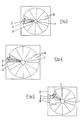
- FIGS. 3 to 5 Illustrated in FIGS. 3 to 5 are exemplary embodiments of staircases of different diameters or conforming, executed with the aid of an identical framework comprising step supports which can be extended in the radial direction.
- Figure 3 shows a staircase having a smaller diameter than the staircase shown in Figure 4, while Figure 5 illustrates a staircase installed in a hopper or volume in an angle of which is disposed a sheath G forming a projection vertical.
- the adjustable helical staircase according to the invention, it comprises a ramp made up of a plurality of modular elements 12 assembled to each other by means of a hinge 17.
- the modular elements 12 are linked together by means of a joint and also with a capacity for longitudinal translation with respect to each other.
- Each ramp element or module 12 comprises an upright 12a and at least one link arm 12b forming an angle with this upright and which can be constituted by the upper part folded 90 degrees from the latter, when said module is executed by means of '' a metal bar or rod of quadrangular or circular section.
- the free end 12d of the link arm 12b has an eye or hole 12c. In this hole is threaded, with an axial translational ability, the amount 12a of one of the neighboring ramp modules and, preferably and in accordance with the illustrated embodiment, the amount of the adjoining module raised. In this way, the assembly of the ramp modules 12 is mainly and simply carried out by simple threading of their upright 12a in the eye 12c of the neighboring ramp module disposed at the lower level.
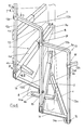
- Each ramp module 12 is fixed, by the lower part of its upright 12a, to a step and, more precisely and advantageously, to the outer end of the spar 4a of the movable element 4 of a step support 2, on the longitudinal axis aa of the latter.
- the lower part of the upright 12a is engaged in the end of the mobile spar 4a of the step support, through the upper hole 6, and it rests on the internal face of the lower wall 4d of said spar.
- the upright 12a and the side member 4a are fixed by means of a screw 13 passing through the hole 7 and screwed into an axial thread which has the lower part of said upright.
- each ramp module 12 is, preferably, connected to the step support and / or to the ramp module neighbor (s) raised (s) by means of a link 14, arranged parallel to the arm 12b of said module.
- a link 14 is fixed to the upright 12a of each ramp module 12, for example by means of a bolt 15, the rod of which passes through aligned bores made in said upright and in an assembly tab 14a constituted by a folded end of said link.
- this rod is fixed, by means of its opposite end provided with a hole 16, by means of the screw 13 passing through said hole.
- the number of steps and. therefore, the number of step supports at the revolution is determined according to the length of the step or width of passage of the steps of the staircase, so that the distance between the axis of the holes 6 and 7 of two successive step supports remains the same.
- the number of ramp modules 12 at revolution is also a function of the diameter of the staircase and the internal angle w that each module forms with any of its two neighboring modules varies as a function of this number, the value of this increasing angle with the increase in the number of the ramp module.
- this adjustable ramp is easily disassembled, for example to pass furniture, and it can be mounted either on the right or on the left, depending on the direction of ascent of the staircase.
- FIG. 9 represents a staircase of diameter smaller than that of the staircase which is illustrated in FIG. 10, the adjustable ramp which equips the latter being composed of a number of ramp modules 12 greater than that which composes the ramp of which with the staircase shown in figure 9.
- the ramp thus formed can be equipped with a handrail (not shown) fixed to the upper part of the ramp modules 12, and various ornaments such as panels, artistic iron fittings, etc., fixed to the uprights 1 2a of said modules.
- the ramp according to the invention adapts to very varied conformations of helical staircases.
- FIG 11 An example of conformation and adaptation of a staircase and its ramp, in the presence of a vertical sheath G '.
- two ramp modules 12 are connected by forming a re-entrant angle to allow the passage of said sheath.
- the invention also allows the realization of conical helical staircases comprising steps of declining radius from bottom to top and whose interest is to allow to pass through small hoppers while encouraging, by their entry lower wider, users to commit to it.
- the ramp easily adapts to the particular configuration of such staircases.
- the ramp in this case, thanks to the fact that the ramp modules 12 are assembled with a latitude of longitudinal movement, in vertical planes, the ramp "absorbs" the variations in height of the steps and automatically adapts to the height of the stairs , without modification of its constituent elements.
- the ramp according to the invention adapts, without any transformation or addition, to the diameters, configurations, conformations and varied heights that the stairs may have.
- step supports when the staircase is mounted in the corner of a room; a certain number of step supports can be lengthened so as to be in contact with the walls and provided with steps also placed in contact with the latter, so that it is possible in this case, not to mount any element or module of ramp close to the walls, which results in significant savings.
- a corner staircase made in this way is shown in Figure 1 2.
- a ramp portion consisting of three elements or ramp modules 12 arranged in extension of each other, is placed on the one of the two open sides of the staircase, at the entrance thereof, while another ramp portion formed by a single ramp module 12 is placed on the second open side of said staircase, at the entrance of the output bearing.
- No ramp module is installed on the closed sides of the staircase, which allows significant savings.
Landscapes
- Engineering & Computer Science (AREA)
- Architecture (AREA)
- Civil Engineering (AREA)
- Structural Engineering (AREA)
- Steps, Ramps, And Handrails (AREA)
- Handcart (AREA)
- Confectionery (AREA)
- Catching Or Destruction (AREA)
- Emergency Lowering Means (AREA)
Priority Applications (1)
| Application Number | Priority Date | Filing Date | Title |
|---|---|---|---|
| AT86430002T ATE42788T1 (de) | 1985-02-01 | 1986-01-30 | Verstellbare spindeltreppe. |
Applications Claiming Priority (2)
| Application Number | Priority Date | Filing Date | Title |
|---|---|---|---|
| FR8501535A FR2576944B1 (fr) | 1985-02-01 | 1985-02-01 | Escalier helicoidal reglable |
| FR8501535 | 1985-02-01 |
Publications (2)
| Publication Number | Publication Date |
|---|---|
| EP0191708A1 true EP0191708A1 (de) | 1986-08-20 |
| EP0191708B1 EP0191708B1 (de) | 1989-05-03 |
Family
ID=9315922
Family Applications (1)
| Application Number | Title | Priority Date | Filing Date |
|---|---|---|---|
| EP86430002A Expired EP0191708B1 (de) | 1985-02-01 | 1986-01-30 | Verstellbare Spindeltreppe |
Country Status (4)
| Country | Link |
|---|---|
| EP (1) | EP0191708B1 (de) |
| AT (1) | ATE42788T1 (de) |
| DE (1) | DE3663161D1 (de) |
| FR (1) | FR2576944B1 (de) |
Cited By (6)
| Publication number | Priority date | Publication date | Assignee | Title |
|---|---|---|---|---|
| WO1992014010A1 (en) * | 1991-02-08 | 1992-08-20 | Olav Nogva | Device relating to winding staircases |
| WO1994008109A1 (de) * | 1992-09-30 | 1994-04-14 | Wilfried Hamm | Geländer aus vorgefertigten normbauteilen |
| DE29708198U1 (de) * | 1997-05-06 | 1997-10-23 | Ambacher, Christoph, 72202 Nagold | Segment-Bau-Treppe |
| FR2848586A1 (fr) * | 2002-12-13 | 2004-06-18 | Schaffner S A | Element modulaire d'escalier et escalier comprenant de tels elements modulaires |
| AT524225A4 (de) * | 2021-02-19 | 2022-04-15 | Minka Holz Und Metallverarbeitungs Gmbh | Stufe für eine Spindeltreppe |
| US11466461B1 (en) * | 2019-04-27 | 2022-10-11 | Luis Jones | Actuatable assemblies |
Citations (6)
| Publication number | Priority date | Publication date | Assignee | Title |
|---|---|---|---|---|
| GB874057A (en) * | 1959-03-10 | 1961-08-02 | Brookfield Art Metals Ltd | Improvements in or relating to spiral staircases |
| BE711586A (de) * | 1968-03-01 | 1968-07-15 | ||
| DE2150050A1 (de) * | 1971-10-07 | 1973-04-12 | Adolf Bucher | Spindeltreppe |
| DE2203889A1 (de) * | 1972-01-28 | 1973-08-02 | Weland & Soehne Gmbh | Wangenlose treppe, insbesondere wendeltreppe |
| FR2233468A1 (de) * | 1973-06-13 | 1975-01-10 | Gieterij Doesburg Bv | |
| FR2501757A1 (fr) * | 1981-03-13 | 1982-09-17 | Archibois | Escalier helicoidal a marche en console en bois reglable sur tube acier |
-
1985
- 1985-02-01 FR FR8501535A patent/FR2576944B1/fr not_active Expired - Fee Related
-
1986
- 1986-01-30 EP EP86430002A patent/EP0191708B1/de not_active Expired
- 1986-01-30 AT AT86430002T patent/ATE42788T1/de active
- 1986-01-30 DE DE8686430002T patent/DE3663161D1/de not_active Expired
Patent Citations (6)
| Publication number | Priority date | Publication date | Assignee | Title |
|---|---|---|---|---|
| GB874057A (en) * | 1959-03-10 | 1961-08-02 | Brookfield Art Metals Ltd | Improvements in or relating to spiral staircases |
| BE711586A (de) * | 1968-03-01 | 1968-07-15 | ||
| DE2150050A1 (de) * | 1971-10-07 | 1973-04-12 | Adolf Bucher | Spindeltreppe |
| DE2203889A1 (de) * | 1972-01-28 | 1973-08-02 | Weland & Soehne Gmbh | Wangenlose treppe, insbesondere wendeltreppe |
| FR2233468A1 (de) * | 1973-06-13 | 1975-01-10 | Gieterij Doesburg Bv | |
| FR2501757A1 (fr) * | 1981-03-13 | 1982-09-17 | Archibois | Escalier helicoidal a marche en console en bois reglable sur tube acier |
Cited By (9)
| Publication number | Priority date | Publication date | Assignee | Title |
|---|---|---|---|---|
| WO1992014010A1 (en) * | 1991-02-08 | 1992-08-20 | Olav Nogva | Device relating to winding staircases |
| WO1994008109A1 (de) * | 1992-09-30 | 1994-04-14 | Wilfried Hamm | Geländer aus vorgefertigten normbauteilen |
| US5667199A (en) * | 1992-09-30 | 1997-09-16 | Hamm; Wilfried | Railing made of prefabricated standard components |
| DE29708198U1 (de) * | 1997-05-06 | 1997-10-23 | Ambacher, Christoph, 72202 Nagold | Segment-Bau-Treppe |
| FR2848586A1 (fr) * | 2002-12-13 | 2004-06-18 | Schaffner S A | Element modulaire d'escalier et escalier comprenant de tels elements modulaires |
| US11466461B1 (en) * | 2019-04-27 | 2022-10-11 | Luis Jones | Actuatable assemblies |
| US12286793B2 (en) | 2019-04-27 | 2025-04-29 | Luis Jones | Guard assemblies |
| AT524225A4 (de) * | 2021-02-19 | 2022-04-15 | Minka Holz Und Metallverarbeitungs Gmbh | Stufe für eine Spindeltreppe |
| AT524225B1 (de) * | 2021-02-19 | 2022-04-15 | Minka Holz Und Metallverarbeitungs Gmbh | Stufe für eine Spindeltreppe |
Also Published As
| Publication number | Publication date |
|---|---|
| ATE42788T1 (de) | 1989-05-15 |
| FR2576944A1 (fr) | 1986-08-08 |
| EP0191708B1 (de) | 1989-05-03 |
| FR2576944B1 (fr) | 1994-02-18 |
| DE3663161D1 (en) | 1989-06-08 |
Similar Documents
| Publication | Publication Date | Title |
|---|---|---|
| FR3074512A1 (fr) | Dispositif d'aide a la construction d'un mur a partir d'elements de structure prefabriques, permettant l'approche, le reglage et le positionnement des elements prefabriques | |
| EP0191708B1 (de) | Verstellbare Spindeltreppe | |
| EP0290351B1 (de) | Zeltplanenträgerrahmen für einen leichten Unterstand | |
| EP0235060B1 (de) | Verbindungsriegel für Balken und mit Hilfe dieser Verbindungsriegel hergestelltes Holztragwerk | |
| EP3199723A1 (de) | Selbsttragende geländer | |
| EP0674741A1 (de) | Justierbares gerüst für schiefe oberflächen | |
| EP3011119B1 (de) | Vorrichtung zum aufbau eines demontierbaren und/oder faltbaren unterstandes | |
| FR2590612A1 (fr) | Garde-corps reglable. | |
| BE1004312A5 (fr) | Meuble comportant une embase munie de roulettes. | |
| EP1109987A1 (de) | Tragbares, als leiter sowie als tritthocker verwendbares gestell | |
| EP1684613A1 (de) | Fasstragvorrichtung | |
| EP0886021A1 (de) | Stützfussvorrichtung für Stange oder Pfosten | |
| FR2775180A1 (fr) | Perfectionnement aux paniers de lave-vaisselle a clayettes | |
| EP0958640B1 (de) | Mast zur verticalen Positionierung zwischen Boden und Decke, insbesondere um den Netzzugang eines Arbeitsplatzes sicherzustellen, und Verfahren zur Positionierung eines derartigen Masts | |
| FR2665920A1 (fr) | Escalier prefabrique en beton pour sous-sol. | |
| EP0835974A1 (de) | Verbindungsorgan | |
| FR2820769A1 (fr) | Panneau garde-corps de securite | |
| BE541845A (de) | ||
| FR2594308A1 (fr) | Pietement de meuble et meuble le comportant | |
| EP3406821A1 (de) | Treppenmodul für wendeltreppe mit sechseckigem querschnitt, anordnung mit mindestens einem solchen modul und treppe, die mindestens eine solche anordnung umfasst | |
| FR2773189A1 (fr) | Escalier d'angle pour bassins de piscines | |
| FR2762770A1 (fr) | Mat-presentoir reglable et auto-stabilisable, pour presentation d'objets divers | |
| FR2883583A1 (fr) | Abri telescopique | |
| FR3052754A1 (fr) | Dispositif de transport d'au moins un objet comportant au moins une plaque | |
| WO2008139084A2 (fr) | Barre de maintien de charge pour vehicule utilitaire et ensemble de barres pour maintien de charge |
Legal Events
| Date | Code | Title | Description |
|---|---|---|---|
| PUAI | Public reference made under article 153(3) epc to a published international application that has entered the european phase |
Free format text: ORIGINAL CODE: 0009012 |
|
| AK | Designated contracting states |
Kind code of ref document: A1 Designated state(s): AT BE CH DE GB IT LI LU NL SE |
|
| 17P | Request for examination filed |
Effective date: 19870115 |
|
| 17Q | First examination report despatched |
Effective date: 19880524 |
|
| GRAA | (expected) grant |
Free format text: ORIGINAL CODE: 0009210 |
|
| AK | Designated contracting states |
Kind code of ref document: B1 Designated state(s): AT BE CH DE GB IT LI LU NL SE |
|
| PG25 | Lapsed in a contracting state [announced via postgrant information from national office to epo] |
Ref country code: SE Effective date: 19890503 Ref country code: NL Effective date: 19890503 Ref country code: GB Effective date: 19890503 Ref country code: AT Effective date: 19890503 |
|
| REF | Corresponds to: |
Ref document number: 42788 Country of ref document: AT Date of ref document: 19890515 Kind code of ref document: T |
|
| REF | Corresponds to: |
Ref document number: 3663161 Country of ref document: DE Date of ref document: 19890608 |
|
| ITF | It: translation for a ep patent filed | ||
| NLV1 | Nl: lapsed or annulled due to failure to fulfill the requirements of art. 29p and 29m of the patents act | ||
| GBV | Gb: ep patent (uk) treated as always having been void in accordance with gb section 77(7)/1977 [no translation filed] | ||
| PG25 | Lapsed in a contracting state [announced via postgrant information from national office to epo] |
Ref country code: LU Free format text: LAPSE BECAUSE OF NON-PAYMENT OF DUE FEES Effective date: 19900131 Ref country code: LI Effective date: 19900131 Ref country code: CH Effective date: 19900131 Ref country code: BE Effective date: 19900131 |
|
| PLBE | No opposition filed within time limit |
Free format text: ORIGINAL CODE: 0009261 |
|
| STAA | Information on the status of an ep patent application or granted ep patent |
Free format text: STATUS: NO OPPOSITION FILED WITHIN TIME LIMIT |
|
| 26N | No opposition filed | ||
| BERE | Be: lapsed |
Owner name: ROLLANT BENOIT Effective date: 19900131 |
|
| REG | Reference to a national code |
Ref country code: CH Ref legal event code: PL |
|
| PG25 | Lapsed in a contracting state [announced via postgrant information from national office to epo] |
Ref country code: DE Effective date: 19901002 |
|
| ITTA | It: last paid annual fee | ||
| PG25 | Lapsed in a contracting state [announced via postgrant information from national office to epo] |
Ref country code: IT Free format text: LAPSE BECAUSE OF NON-PAYMENT OF DUE FEES Effective date: 20050130 |