EP0191719A1 - Disjoncteur basse tension muni d'un transformateur de courant - Google Patents
Disjoncteur basse tension muni d'un transformateur de courant Download PDFInfo
- Publication number
- EP0191719A1 EP0191719A1 EP86730012A EP86730012A EP0191719A1 EP 0191719 A1 EP0191719 A1 EP 0191719A1 EP 86730012 A EP86730012 A EP 86730012A EP 86730012 A EP86730012 A EP 86730012A EP 0191719 A1 EP0191719 A1 EP 0191719A1
- Authority
- EP
- European Patent Office
- Prior art keywords
- current transformer
- circuit breaker
- low
- voltage circuit
- carrier
- Prior art date
- Legal status (The legal status is an assumption and is not a legal conclusion. Google has not performed a legal analysis and makes no representation as to the accuracy of the status listed.)
- Granted
Links
- XEEYBQQBJWHFJM-UHFFFAOYSA-N Iron Chemical group [Fe] XEEYBQQBJWHFJM-UHFFFAOYSA-N 0.000 claims description 6
- 210000002414 leg Anatomy 0.000 description 6
- 230000006835 compression Effects 0.000 description 3
- 238000007906 compression Methods 0.000 description 3
- 238000004804 winding Methods 0.000 description 2
- 230000004308 accommodation Effects 0.000 description 1
- 230000008878 coupling Effects 0.000 description 1
- 238000010168 coupling process Methods 0.000 description 1
- 238000005859 coupling reaction Methods 0.000 description 1
- 230000002349 favourable effect Effects 0.000 description 1
- 230000037431 insertion Effects 0.000 description 1
- 238000003780 insertion Methods 0.000 description 1
- 239000011810 insulating material Substances 0.000 description 1
- 239000012212 insulator Substances 0.000 description 1
- 229910052742 iron Inorganic materials 0.000 description 1
- 210000003127 knee Anatomy 0.000 description 1
- 238000004519 manufacturing process Methods 0.000 description 1
- 239000000463 material Substances 0.000 description 1
Images

Classifications
-
- H—ELECTRICITY
- H01—ELECTRIC ELEMENTS
- H01H—ELECTRIC SWITCHES; RELAYS; SELECTORS; EMERGENCY PROTECTIVE DEVICES
- H01H71/00—Details of the protective switches or relays covered by groups H01H73/00 - H01H83/00
- H01H71/08—Terminals; Connections
-
- H—ELECTRICITY
- H02—GENERATION; CONVERSION OR DISTRIBUTION OF ELECTRIC POWER
- H02B—BOARDS, SUBSTATIONS OR SWITCHING ARRANGEMENTS FOR THE SUPPLY OR DISTRIBUTION OF ELECTRIC POWER
- H02B11/00—Switchgear having carriage withdrawable for isolation
- H02B11/26—Arrangements of fuses, resistors, voltage arresters or the like
Definitions
- the invention relates to a low-voltage circuit breaker with a carrier for a contact arrangement and connecting rails and with a current transformer enclosing the connecting rail, the carrier being designed to accommodate the current transformer.
- a power shader of this type is known from US Pat. No. 3,584,170. Due to the angled shape of the carrier, the rear connection rails of the circuit breaker have unequal lengths. Therefore, the forces acting on the connection points act on the longer connection rail enclosed by the current transformer with a larger lever arm. This can lead to excessive stress on the connecting rails and the support of the contact arrangements, in particular when the power controller is permanently installed in a switchgear.
- the object of the invention is to provide an accommodation of the current transformer in the circuit breaker which, on the one hand, permits replacement with reasonable effort, but on the other hand results in high strength in the area of the connecting rails.
- the current transformer is supported on a stationary part of the circuit breaker independently of the connecting rails assigned to the current transformer and by an insulating piece inserted between the connecting rails and containing threaded holes for clamping screws of the connecting rails.
- the insulating piece stiffens the connecting rails in such a way that that they can absorb much higher forces originating from the continuing busbars without the risk of damage. If the current transformer is to be replaced, it is essentially sufficient to remove this insulating piece in order to make the current transformer accessible.
- a cross member connecting the side walls of the circuit breaker can serve as a stationary part for supporting the current transformer. Since such a crossmember is generally part of conventional circuit breakers, it is sufficient for the present purpose to adapt the dimensions of the fastening elements of the current transformer to the position of such a crossmember, or to mount the crossmember without impairing its other functions in a manner that is favorable for supporting the Current transformer
- the current transformer can have two coil formers which are intended to be pushed onto a rectangular iron core and which are provided in a symmetrical arrangement with attachment points for foot parts. This has the advantage that the coil body for two windings of the current transformer can be assembled from partial bodies of half the size, the shape of which is simplified in that the complete foot parts are missing. These are easier to manufacture than small individual parts that are attached to the attachment points of the coil formers. It is advisable to provide the starting points of the bobbin and the foot parts with interacting projections or undercuts.
- a relatively simple releasable fastening arrangement is sufficient in the area of the foot parts.
- This may consist in the fact that the stationary part of the power switch, in particular the mentioned crossmember, holes accessible from below for fastening elements acting on the current transformer, e.g. B. has one screw per foot part.
- a substantial stiffening of the connecting rails results from the mere insertion of the insulating piece.
- An additional stiffening can be achieved in that the insulating piece is detachably attached to a stationary part of the circuit breaker with freely accessible fastening elements. This can be done by screwing the insulating piece to the designated support points on the side walls of the circuit breaker or by providing the carrier of the contact arrangements with threaded holes in order to fasten the insulating piece to the carrier.
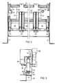
- Figure 1 shows a circuit breaker in section.
- the power shader is shown from the rear, different versions of an insulating piece inserted between the connecting rails being shown on both sides of a dash-dotted center line.
- Figure 3 is a side view of a current transformer and subsequent parts of a circuit breaker.
- the low-voltage power switch 1 shown in FIG. 1 is shown in simplified form in the section of a pole and the switching lock.
- the circuit breaker 1 has two side walls 2 and 3 as supporting components, one side wall 2 of which is visible in FIG. 1, while both side walls 2 and 3 are shown in FIG.
- An insulating carrier 4 for three adjacent contact arrangements extends between the side walls 2 and 3.
- the current path of each pole comprises, starting from an upper, forked connecting rail 5 with partial rails 6 and 7, a fixed shaft piece 10, a movable switching lever 11, a flexible current band 12 and a lower connection Rail 13, which is also composed of partial rails 14 and 15.
- the contact lever 11 is articulated on a contact carrier 16, which can be pivoted about a stationary pivot bearing 17 21 on.
- a toggle lever arrangement comprising three articulated toggle levers 24, 25 and 26 engages, which in the illustrated switch-on position of the circuit breaker by a support lever 27 and a latch lever 30 is supported on a half shaft 31.
- a rotation of the Hafbwelle 3 1 by a trigger, not shown, or by hand using a pushbutton 32 cancels the support of the knee lifting system and causes it to buckle.
- the contact carrier 16 and the contact lever 11 then take the off position under the influence of a compression spring 33.
- the energy required to switch on is stored in a manner not shown by tensioning one or more helical compression springs 38 which are supported at one end on a crossbar 34 connecting the side walls 2 and 3 and which acts on the lower toggle lever 26 at their other end
- Tensioned compression spring 38 can be locked in a manner known per se, a further push button 35 being provided for releasing this locking and thus for switching on the circuit breaker
- the support 4 which is made of an insulating material, is angled, one leg 36 of the angular shape having fastening means for fixing the connection rails 5 and 13 on the switch side.
- the further leg 37 of the carrier 4 is dimensioned such that it corresponds approximately to the dimension of a current transformer 40 lying in the longitudinal direction of the connecting rails.
- the current transformer 40 has an iron core 41 which carries a coil former consisting of two partial bodies 42
- the current transformer 40 surrounds the lower connection rail 13 of the circuit breaker 1 at a distance and is supported independently of this connection rail.
- three identical current transformers 40 are provided in accordance with the three-pole version of the circuit breaker 1.
- the lower coil former 42 of each of these current transformers is provided with base parts 43. With these, the current transformers rest on the crossmember 34, in which there are through holes (not shown) for one fastening screw 44 for each foot part 43.
- the cross member 3 4 as shown in particular in FIGS. 1 and 3, is designed so that there is unhindered access to the fastening screws 44 from below.
- the further down the current transformer 4 0 takes place 43 opposite part at its the leg portions, ie in the region of the upper part of the bobbin 42.
- an insulating piece 46 which is inserted between the connecting rails 5 and 13, the insulator 46 is cut in the figure 1 partially shown in order to make visible clamping screws 47 engaging in the insulating piece, which are provided for connecting bus bars 50 to the connecting bars 5 and 13.
- the connecting rails 50 are shown broken off in FIG. 1 and are overlapped by the partial rails 6 and 7 or 14 and 15.
- the insulating piece 46 forms a stable stiffening of the connecting rails 5 and 13. At the same time, it defines the current transformer 40 with a small tolerance
- a distance can be seen between the insulating piece 46 and the upper leg 37 of the carrier 4. This is based on the fact that the insulating piece 46 is not directly connected to the carrier 4, but is screwed at its ends to abutments of the side walls 2 and 3 as shown in the left part of FIG. 2.
- a support bent out of the one side wall denoted by 51 and a connecting screw by 52. This arrangement is analogously provided on both side walls 2 and 3.
- the connection to the carrier 4 is shown in the right part of FIG.
- the insulating piece 4 8 is fastened to the leg 37 with screws 49. This is provided with screw holes (not shown), for example in the middle of each pole.
- the space between the leg 37 and the insulating piece 46 shown in FIG. 1 and already mentioned is omitted.
- the distance between the insulating piece 48 and the leg 36 of the carrier 4 is to be dimensioned according to the dimensions of the current transformer 40.
- the current transformer 40 contains an iron comb 41 and two partial coil formers 42. According to FIG. 3, these are provided with attachment points 55 for the base parts 43 and can thus be used either as upper or lower partial coil formers, one attachment point remaining unused 55 are provided with undercuts 60, which correspond to projections 6 1 of the foot parts 4 3. In this way, the foot parts 43 can be positively anchored to the coil former.
Landscapes
- Engineering & Computer Science (AREA)
- Power Engineering (AREA)
- Breakers (AREA)
- Transformers For Measuring Instruments (AREA)
Applications Claiming Priority (2)
| Application Number | Priority Date | Filing Date | Title |
|---|---|---|---|
| DE19853504423 DE3504423A1 (de) | 1985-02-07 | 1985-02-07 | Niederspannungs-leistungsschalter mit einem stromwandler |
| DE3504423 | 1985-02-07 |
Publications (2)
| Publication Number | Publication Date |
|---|---|
| EP0191719A1 true EP0191719A1 (fr) | 1986-08-20 |
| EP0191719B1 EP0191719B1 (fr) | 1989-05-31 |
Family
ID=6262069
Family Applications (1)
| Application Number | Title | Priority Date | Filing Date |
|---|---|---|---|
| EP86730012A Expired EP0191719B1 (fr) | 1985-02-07 | 1986-01-28 | Disjoncteur basse tension muni d'un transformateur de courant |
Country Status (5)
| Country | Link |
|---|---|
| US (1) | US4673779A (fr) |
| EP (1) | EP0191719B1 (fr) |
| JP (1) | JPS61183836A (fr) |
| DE (2) | DE3504423A1 (fr) |
| IN (1) | IN163086B (fr) |
Families Citing this family (5)
| Publication number | Priority date | Publication date | Assignee | Title |
|---|---|---|---|---|
| JP3210820B2 (ja) * | 1994-11-15 | 2001-09-25 | 松下電工株式会社 | 漏電遮断器 |
| DE10004833A1 (de) * | 2000-02-01 | 2001-08-02 | Siemens Ag | Mehrpoliger Niederspannungs-Leistungsschalter mit einem Stromerfassungsgerät je Pol |
| DE10219561A1 (de) * | 2002-04-26 | 2003-11-13 | Siemens Ag | Elektrischer Leistungsschalter mit einem Stromwandler |
| US7511229B2 (en) * | 2005-06-02 | 2009-03-31 | Liebert Corporation | Sensor module, system, and method for sensors in proximity to circuit breakers |
| FR3028348B1 (fr) | 2014-11-10 | 2016-12-30 | Schneider Electric Ind Sas | Declencheur pour dispositif de commutation electrique et dispositif de commutation electrique comprenant un tel declencheur |
Citations (3)
| Publication number | Priority date | Publication date | Assignee | Title |
|---|---|---|---|---|
| US3584170A (en) * | 1968-10-24 | 1971-06-08 | Westinghouse Electric Corp | Circuit interrupter having an improved insulating support structure |
| EP0068934A1 (fr) * | 1981-06-05 | 1983-01-05 | Merlin Gerin | Disjoncteur multipolaire à boîtier moulé et à déclencheur statique |
| EP0071385A2 (fr) * | 1981-07-17 | 1983-02-09 | Mitsubishi Denki Kabushiki Kaisha | Assemblage de bornes de connexion pour disjoncteur |
Family Cites Families (1)
| Publication number | Priority date | Publication date | Assignee | Title |
|---|---|---|---|---|
| JPS4911259U (fr) * | 1972-05-04 | 1974-01-30 |
-
1985
- 1985-02-07 DE DE19853504423 patent/DE3504423A1/de not_active Withdrawn
-
1986
- 1986-01-21 IN IN40/CAL/86A patent/IN163086B/en unknown
- 1986-01-23 US US06/821,849 patent/US4673779A/en not_active Expired - Fee Related
- 1986-01-28 EP EP86730012A patent/EP0191719B1/fr not_active Expired
- 1986-01-28 DE DE8686730012T patent/DE3663761D1/de not_active Expired
- 1986-02-04 JP JP61022803A patent/JPS61183836A/ja active Granted
Patent Citations (3)
| Publication number | Priority date | Publication date | Assignee | Title |
|---|---|---|---|---|
| US3584170A (en) * | 1968-10-24 | 1971-06-08 | Westinghouse Electric Corp | Circuit interrupter having an improved insulating support structure |
| EP0068934A1 (fr) * | 1981-06-05 | 1983-01-05 | Merlin Gerin | Disjoncteur multipolaire à boîtier moulé et à déclencheur statique |
| EP0071385A2 (fr) * | 1981-07-17 | 1983-02-09 | Mitsubishi Denki Kabushiki Kaisha | Assemblage de bornes de connexion pour disjoncteur |
Also Published As
| Publication number | Publication date |
|---|---|
| IN163086B (fr) | 1988-08-06 |
| JPH0320854B2 (fr) | 1991-03-20 |
| DE3504423A1 (de) | 1986-08-07 |
| US4673779A (en) | 1987-06-16 |
| JPS61183836A (ja) | 1986-08-16 |
| DE3663761D1 (en) | 1989-07-06 |
| EP0191719B1 (fr) | 1989-05-31 |
Similar Documents
| Publication | Publication Date | Title |
|---|---|---|
| EP0554519B1 (fr) | Borne de raccordement avec mise à la terre | |
| DE69610741T2 (de) | Vorrichtung zur elektrischen Verbindung von modularen Geräten wie Schaltern oder dergleichen | |
| DE3615707C2 (fr) | ||
| DE2809852C2 (de) | Sammelschienensystem einer elektrischen Hochspannungsschaltvorrichtung | |
| DE69905932T2 (de) | Stromschiene für eine elektrische energieverteilung | |
| DE4013225A1 (de) | Schraubanschlussklemme, insbesondere fuer ein an gleiche oder gleichartige geraete anreihbares schaltgeraet | |
| DE2619506C3 (de) | Elektrische Reihenklemme | |
| EP0191719A1 (fr) | Disjoncteur basse tension muni d'un transformateur de courant | |
| EP1249910A2 (fr) | Disjoncteur haute-tension pour une installation de commutation à isolation gaseuse | |
| DE69603000T2 (de) | Elektrische Anschlussleiste | |
| EP0223732B1 (fr) | Disjoncteur multipolaire de puissance basse tension avec barres de courant | |
| AT4111U1 (de) | Stromleiter für stromwandler einer nh-sicherungs-einrichtung oder nh-sicherungs-lastschalteinrichtung | |
| EP1251537B1 (fr) | Disjoncteur-sectionneur à fusibles du type baguette | |
| DE2855205C2 (de) | Mehrpoliges Mittelspannungsschaltgerät mit stufenloser Einstellung von unterschiedlichen Polmittenabständen | |
| DE10260402B4 (de) | Einrichtung zur Herstellung einer unter Kontaktkraft gehaltenen stromleitenden Überbrückung und elektrisches Erdungsgerät mit einer derartigen Einrichtung | |
| EP0227585B1 (fr) | Dispositif de sectionnement pour appareils interrupteurs montés d'une façon déplaçable sur glissières | |
| DE702168C (de) | Zaehler- oder Verteilungsrahmentafel fuer Hausstromnetze o. dgl. aus Isolierpressstoff | |
| DE2515692B2 (de) | Nh-sicherungsunterteil zum aufsetzen auf sammelschienen | |
| DE3316918C2 (fr) | ||
| DE69114584T2 (de) | Stromwandlerbefestigungsvorrichtung für ein Schutzschalter. | |
| DE69305147T2 (de) | Kontaktvorrichtung | |
| DE3217961C2 (fr) | ||
| DE1515930C3 (de) | Dreipoliger Mittelspannungsschalter in isolierstoffgekapselter Bauweise | |
| DE1590273C (de) | Vorrichtung zum Tragen eines Leiters dreiphasiger Sammelschienen und eines Einfahrgegenkontaktstuckes einer Mittelspannungsschaltanlage | |
| WO1997044799A1 (fr) | Sectionneur de puissance basse tension pourvu d'un porte-contact |
Legal Events
| Date | Code | Title | Description |
|---|---|---|---|
| PUAI | Public reference made under article 153(3) epc to a published international application that has entered the european phase |
Free format text: ORIGINAL CODE: 0009012 |
|
| AK | Designated contracting states |
Kind code of ref document: A1 Designated state(s): DE FR GB IT SE |
|
| 17P | Request for examination filed |
Effective date: 19860923 |
|
| 17Q | First examination report despatched |
Effective date: 19880707 |
|
| GRAA | (expected) grant |
Free format text: ORIGINAL CODE: 0009210 |
|
| AK | Designated contracting states |
Kind code of ref document: B1 Designated state(s): DE FR GB IT SE |
|
| REF | Corresponds to: |
Ref document number: 3663761 Country of ref document: DE Date of ref document: 19890706 |
|
| ET | Fr: translation filed | ||
| ITF | It: translation for a ep patent filed | ||
| GBT | Gb: translation of ep patent filed (gb section 77(6)(a)/1977) | ||
| PLBE | No opposition filed within time limit |
Free format text: ORIGINAL CODE: 0009261 |
|
| STAA | Information on the status of an ep patent application or granted ep patent |
Free format text: STATUS: NO OPPOSITION FILED WITHIN TIME LIMIT |
|
| 26N | No opposition filed | ||
| ITTA | It: last paid annual fee | ||
| EAL | Se: european patent in force in sweden |
Ref document number: 86730012.1 |
|
| PGFP | Annual fee paid to national office [announced via postgrant information from national office to epo] |
Ref country code: GB Payment date: 19951218 Year of fee payment: 11 |
|
| PGFP | Annual fee paid to national office [announced via postgrant information from national office to epo] |
Ref country code: SE Payment date: 19960119 Year of fee payment: 11 |
|
| PG25 | Lapsed in a contracting state [announced via postgrant information from national office to epo] |
Ref country code: GB Effective date: 19970128 |
|
| PG25 | Lapsed in a contracting state [announced via postgrant information from national office to epo] |
Ref country code: SE Effective date: 19970129 |
|
| GBPC | Gb: european patent ceased through non-payment of renewal fee |
Effective date: 19970128 |
|
| EUG | Se: european patent has lapsed |
Ref document number: 86730012.1 |
|
| PGFP | Annual fee paid to national office [announced via postgrant information from national office to epo] |
Ref country code: FR Payment date: 20010112 Year of fee payment: 16 |
|
| PGFP | Annual fee paid to national office [announced via postgrant information from national office to epo] |
Ref country code: DE Payment date: 20010319 Year of fee payment: 16 |
|
| PG25 | Lapsed in a contracting state [announced via postgrant information from national office to epo] |
Ref country code: DE Free format text: LAPSE BECAUSE OF NON-PAYMENT OF DUE FEES Effective date: 20020801 |
|
| PG25 | Lapsed in a contracting state [announced via postgrant information from national office to epo] |
Ref country code: FR Free format text: LAPSE BECAUSE OF NON-PAYMENT OF DUE FEES Effective date: 20020930 |
|
| REG | Reference to a national code |
Ref country code: FR Ref legal event code: ST |
|
| PG25 | Lapsed in a contracting state [announced via postgrant information from national office to epo] |
Ref country code: IT Free format text: LAPSE BECAUSE OF NON-PAYMENT OF DUE FEES;WARNING: LAPSES OF ITALIAN PATENTS WITH EFFECTIVE DATE BEFORE 2007 MAY HAVE OCCURRED AT ANY TIME BEFORE 2007. THE CORRECT EFFECTIVE DATE MAY BE DIFFERENT FROM THE ONE RECORDED. Effective date: 20050128 |