EP0192006A1 - Kraftfahrzeugsitz - Google Patents
Kraftfahrzeugsitz Download PDFInfo
- Publication number
- EP0192006A1 EP0192006A1 EP85402513A EP85402513A EP0192006A1 EP 0192006 A1 EP0192006 A1 EP 0192006A1 EP 85402513 A EP85402513 A EP 85402513A EP 85402513 A EP85402513 A EP 85402513A EP 0192006 A1 EP0192006 A1 EP 0192006A1
- Authority
- EP
- European Patent Office
- Prior art keywords
- nacelle
- chassis
- axis
- relative
- vehicle seat
- Prior art date
- Legal status (The legal status is an assumption and is not a legal conclusion. Google has not performed a legal analysis and makes no representation as to the accuracy of the status listed.)
- Granted
Links
- 230000003100 immobilizing effect Effects 0.000 claims abstract description 4
- 230000007246 mechanism Effects 0.000 claims description 7
- 239000000463 material Substances 0.000 claims description 2
- 239000004033 plastic Substances 0.000 claims description 2
- 239000002991 molded plastic Substances 0.000 abstract description 2
- XEEYBQQBJWHFJM-UHFFFAOYSA-N Iron Chemical compound [Fe] XEEYBQQBJWHFJM-UHFFFAOYSA-N 0.000 description 2
- 230000000284 resting effect Effects 0.000 description 2
- 210000003813 thumb Anatomy 0.000 description 2
- 238000006073 displacement reaction Methods 0.000 description 1
- 229910052742 iron Inorganic materials 0.000 description 1
Images



Classifications
-
- B—PERFORMING OPERATIONS; TRANSPORTING
- B60—VEHICLES IN GENERAL
- B60N—SEATS SPECIALLY ADAPTED FOR VEHICLES; VEHICLE PASSENGER ACCOMMODATION NOT OTHERWISE PROVIDED FOR
- B60N2/00—Seats specially adapted for vehicles; Arrangement or mounting of seats in vehicles
- B60N2/02—Seats specially adapted for vehicles; Arrangement or mounting of seats in vehicles the seat or part thereof being movable, e.g. adjustable
- B60N2/04—Seats specially adapted for vehicles; Arrangement or mounting of seats in vehicles the seat or part thereof being movable, e.g. adjustable the whole seat being movable
- B60N2/16—Seats specially adapted for vehicles; Arrangement or mounting of seats in vehicles the seat or part thereof being movable, e.g. adjustable the whole seat being movable height-adjustable
- B60N2/18—Seats specially adapted for vehicles; Arrangement or mounting of seats in vehicles the seat or part thereof being movable, e.g. adjustable the whole seat being movable height-adjustable the front or the rear portion of the seat being adjustable, e.g. independently of each other
- B60N2/1807—Seats specially adapted for vehicles; Arrangement or mounting of seats in vehicles the seat or part thereof being movable, e.g. adjustable the whole seat being movable height-adjustable the front or the rear portion of the seat being adjustable, e.g. independently of each other characterised by the cinematic
- B60N2/1842—Seats specially adapted for vehicles; Arrangement or mounting of seats in vehicles the seat or part thereof being movable, e.g. adjustable the whole seat being movable height-adjustable the front or the rear portion of the seat being adjustable, e.g. independently of each other characterised by the cinematic pivoting about an axis located in the rear
-
- B—PERFORMING OPERATIONS; TRANSPORTING
- B60—VEHICLES IN GENERAL
- B60N—SEATS SPECIALLY ADAPTED FOR VEHICLES; VEHICLE PASSENGER ACCOMMODATION NOT OTHERWISE PROVIDED FOR
- B60N2/00—Seats specially adapted for vehicles; Arrangement or mounting of seats in vehicles
- B60N2/02—Seats specially adapted for vehicles; Arrangement or mounting of seats in vehicles the seat or part thereof being movable, e.g. adjustable
- B60N2/04—Seats specially adapted for vehicles; Arrangement or mounting of seats in vehicles the seat or part thereof being movable, e.g. adjustable the whole seat being movable
- B60N2/16—Seats specially adapted for vehicles; Arrangement or mounting of seats in vehicles the seat or part thereof being movable, e.g. adjustable the whole seat being movable height-adjustable
- B60N2/18—Seats specially adapted for vehicles; Arrangement or mounting of seats in vehicles the seat or part thereof being movable, e.g. adjustable the whole seat being movable height-adjustable the front or the rear portion of the seat being adjustable, e.g. independently of each other
- B60N2/185—Seats specially adapted for vehicles; Arrangement or mounting of seats in vehicles the seat or part thereof being movable, e.g. adjustable the whole seat being movable height-adjustable the front or the rear portion of the seat being adjustable, e.g. independently of each other characterised by the drive mechanism
- B60N2/1875—Racks
-
- B—PERFORMING OPERATIONS; TRANSPORTING
- B60—VEHICLES IN GENERAL
- B60N—SEATS SPECIALLY ADAPTED FOR VEHICLES; VEHICLE PASSENGER ACCOMMODATION NOT OTHERWISE PROVIDED FOR
- B60N2/00—Seats specially adapted for vehicles; Arrangement or mounting of seats in vehicles
- B60N2/02—Seats specially adapted for vehicles; Arrangement or mounting of seats in vehicles the seat or part thereof being movable, e.g. adjustable
- B60N2/04—Seats specially adapted for vehicles; Arrangement or mounting of seats in vehicles the seat or part thereof being movable, e.g. adjustable the whole seat being movable
- B60N2/16—Seats specially adapted for vehicles; Arrangement or mounting of seats in vehicles the seat or part thereof being movable, e.g. adjustable the whole seat being movable height-adjustable
- B60N2/18—Seats specially adapted for vehicles; Arrangement or mounting of seats in vehicles the seat or part thereof being movable, e.g. adjustable the whole seat being movable height-adjustable the front or the rear portion of the seat being adjustable, e.g. independently of each other
- B60N2/1896—Stepwise movement mechanisms, e.g. ratchets
Definitions
- the present invention relates to a vehicle seat comprising a chassis which is slidably mounted longitudinally with respect to the structure of the vehicle and supports a nacelle made of a molded or stamped plastic material.
- the seat according to the invention is characterized in that the nacelle is pivotally mounted relative to the chassis around a horizontal axis from which it can be detached and comprises a seat shell pivotally mounted at one of its ends relative to the nacelle, and in that it is provided with means for immobilizing in the desired position on the one hand the nacelle relative to the chassis and on the other hand the seat shell relative to the nacelle.
- the chassis comprises a horizontal axis pivotally mounted, on one end of which is fixed a control lever external to the nacelle and which is integral with a lever carrying a pin interposed between two pawls or levers pivotally mounted freely on said axis, one of these pawls or levers being connected to a locking piece capable of maintaining the axis of tilting of the nacelle, while the other lever or pawl carries a latch capable of engaging in a toothed sector of the nacelle in order to block its tilting , elastic means acting on these levers and tending to maintain them in positions in which the nacelle is secured to the chassis by its tilting axis and is prevented from tilting relative to this chassis.
- the same lever thus makes it possible either to separate the nacelle from the chassis if it is pivoted in one direction, or to allow its tilting if it is pivoted in the opposite direction.
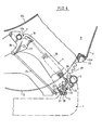
- the seat according to the invention comprises a chassis which is designated in the drawing by the reference 1 and can slide longitudinally relative to the chassis of the vehicle, on the interior side by means of ball slides 2 and on the outside thanks to sliding pads 3.
- the frame 1 is constituted by a mechanism-carrying flange 4 which is arranged on the outside of the seat and is connected by a folded tube 5 to a plate 6 arranged on the inside.
- the flange 4 and the plate 6 have at their upper part a recess respectively 7 or 8 forming a bearing, the two recesses being arranged at the same height and, more precisely coaxial both at the same transverse axis perpendicular to the flange and to the plate .
- the seat also includes a nacelle 9 made of molded plastic. This is formed by two hollow sides 10a and 10b joined to each other by a dorsal part 11, and a seat shell 12. Each of the sides 10a and 10b is hollow and carries a transverse axis 13a or 13b, the two axes being collinear.
- the nacelle 9 can be mounted on the chassis 1 so that its sides 10a and 10b respectively envelop the flange 4 and the plate 6, the axes 13a and 13b resting in the bearings 7 and 8.
- a mechanism for locking the axes or pivots 13a and 13b in their bearings 7 and 8 and for adjusting the inclination of the nacelle 9 relative to the chassis 1 is arranged in each of the sides 10a and 10b.
- This mechanism comprises a lever 14 which is integral with a transverse axis 15 extending over the entire width of the seat.
- This axis is pivotally mounted in bearings 16 and 17 carried respectively by the flange 4 and by an iron 18 welded under the tube 5 and carrying the movable element of the slide 2.
- the axis 15 carries an operating lever 19 at its end located on the outside of the seat.
- the lever 14 carries a pin 20 which is engaged between two spouts 21 and 22 of two levers 23 and 24 superimposed and mounted to pivot freely on the axis 15.
- the lever 23 is connected by a connecting rod 25 to a locking pin 26 which is mounted pivoting about an axis 27 relative to the side 10a or 10b and makes it possible to maintain the axis 13a or 13b respectively in its bearing 7 or 8.
- the lever 24 forms a pawl and has a lug 28 which can engage between two teeth of a toothing 29 provided on the inner face of each of the sides 10a and lOb.
- a spring 30 connects the pawl 24 to the bolt 26. The end of this spring attached to the bolt 26 passes through a buttonhole 31 formed in the flange 4.
- a spring 32 is interposed between the bearing 16 and the lever 23; this spring keeps the levers 23 and 24 pressing against the corresponding lever 14.
- lever 19 If the lever 19 is pivoted in the direction indicated by the arrow f l in Figure 1, this lever drives the levers 23 via the pins 20 of the levers 14.
- the connecting rods 25 rotate the bolts 26 which release the axes 13a and 13b of their bearings 7 and 8. It is then possible to extract the nacelle 9 from the chassis 1.
- the locking mechanism is crazy and can take any position of equilibrium compatible with the travel in the buttonhole 31, from the end of the spring attached to the bolt 26.
- the pins 20 drive the levers 24 whose lugs 28 are released from the teeth 29. It is then possible to tilt the nacelle around the axis levels 7 and 8 and modify the position of the seat dihedral; when the lever 19 is then released, the springs 30 ensure the re-engagement of the tabs 28 in the teeth 29 and, consequently, the immobilization of the nacelle in the new chosen position.
- the rear end 12a of the seat shell 12 is folded and engaged with play in a slot 33 formed in the dorsal part 11 of the nacelle 9 ( Figure 4). At its front end, it carries on each side a sector 34 comprising a toothing 35.
- Each of the sides 10a and 10b of the nacelle carries an oblong bearing 36.
- An axis 37 extends over the entire width of the nacelle and rests in the oblong bearings 36.
- This axis is integral with an operating wheel 38 disposed at the end of the nacelle, and comprises two pairs of pins 39 and 40 each arranged opposite each toothing 35, the two pins 39 and 40 of the same pair being spaced from each other by a distance equal to the pitch of these teeth 35.
- Two springs 41 coupled to the axis 37 and to the nacelle and each arranged in one of the sides 10a and 10b, hold the pins 39 and 40 in the teeth 35.
- the reference 42 designates a lever which makes it possible, in a known manner, to immobilize the chassis 1 on its slides.
- Each of the sides 10a and 10b is provided at its lower part, with support legs 43.
- the nacelle 9 can be separated from the chassis on which it is normally fixed. The nacelle can then be used as a seat outside the vehicle by resting on the feet 43. When the nacelle is in place in the vehicle, one can both adjust its longitudinal position by acting on the lever 42, its angular position by acting on the lever 19, and the inclination of the seat by operating the thumb wheel 38.
Landscapes
- Engineering & Computer Science (AREA)
- Aviation & Aerospace Engineering (AREA)
- Transportation (AREA)
- Mechanical Engineering (AREA)
- Seats For Vehicles (AREA)
Applications Claiming Priority (2)
| Application Number | Priority Date | Filing Date | Title |
|---|---|---|---|
| FR8420175 | 1984-12-28 | ||
| FR8420175A FR2575425B1 (fr) | 1984-12-28 | 1984-12-28 | Siege de vehicule automobile |
Publications (2)
| Publication Number | Publication Date |
|---|---|
| EP0192006A1 true EP0192006A1 (de) | 1986-08-27 |
| EP0192006B1 EP0192006B1 (de) | 1988-02-03 |
Family
ID=9311190
Family Applications (1)
| Application Number | Title | Priority Date | Filing Date |
|---|---|---|---|
| EP19850402513 Expired EP0192006B1 (de) | 1984-12-28 | 1985-12-17 | Kraftfahrzeugsitz |
Country Status (3)
| Country | Link |
|---|---|
| EP (1) | EP0192006B1 (de) |
| DE (1) | DE3561538D1 (de) |
| FR (1) | FR2575425B1 (de) |
Cited By (5)
| Publication number | Priority date | Publication date | Assignee | Title |
|---|---|---|---|---|
| WO2012064922A3 (en) * | 2010-11-10 | 2012-10-26 | Weber Aircraft Llc | Swiveling passenger seat |
| USD682568S1 (en) | 2011-11-10 | 2013-05-21 | Zodiac Seats Us Llc | Swiveling passenger seat |
| USD682567S1 (en) | 2011-11-10 | 2013-05-21 | Zodiac Seats US LLP | Swiveling passenger seat |
| USD682569S1 (en) | 2011-11-10 | 2013-05-21 | Zodiac Seats Us Llc | Swiveling passenger seat |
| USD682570S1 (en) | 2011-11-10 | 2013-05-21 | Zodiac Seats Us Llc | Swiveling passenger seat |
Citations (11)
| Publication number | Priority date | Publication date | Assignee | Title |
|---|---|---|---|---|
| FR1448282A (fr) * | 1965-06-24 | 1966-08-05 | Expl Textile Et Metallurg L | Perfectionnement aux sièges réglables pour véhicules |
| US3313571A (en) * | 1965-10-11 | 1967-04-11 | Gen Motors Corp | Removable and stackable seating arrangement |
| US3357736A (en) * | 1966-05-17 | 1967-12-12 | John J Mccarthy | Vehicle seat |
| DE1703221A1 (de) * | 1968-04-19 | 1971-04-15 | Porsche Kg | Kampffahrzeug mit einer Sichtkuppel |
| US3582133A (en) * | 1967-07-31 | 1971-06-01 | Peugeot | Energy absorbing arrangement for seat on a vehicle |
| FR2120277A5 (de) * | 1970-12-28 | 1972-08-18 | Peugeot & Renault | |
| FR2129678A5 (de) * | 1971-03-15 | 1972-10-27 | Chrysler Uk | |
| US3819232A (en) * | 1972-08-21 | 1974-06-25 | Gen Motors Corp | Vehicle seat construction |
| FR2402431A1 (fr) * | 1977-09-09 | 1979-04-06 | Alusuisse | Coquille pour siege, en particulier pour siege de vehicule |
| EP0028564A1 (de) * | 1979-11-05 | 1981-05-13 | Societe Industrielle Bertrand Faure | Fahrzeugsitz mit zumindest einer Sitzschale |
| EP0029377A1 (de) * | 1979-11-14 | 1981-05-27 | Societe Industrielle Bertrand Faure | Verstellbare Fahrzeugsitze und deren Verstellmechanismus |
-
1984
- 1984-12-28 FR FR8420175A patent/FR2575425B1/fr not_active Expired
-
1985
- 1985-12-17 EP EP19850402513 patent/EP0192006B1/de not_active Expired
- 1985-12-17 DE DE8585402513T patent/DE3561538D1/de not_active Expired
Patent Citations (11)
| Publication number | Priority date | Publication date | Assignee | Title |
|---|---|---|---|---|
| FR1448282A (fr) * | 1965-06-24 | 1966-08-05 | Expl Textile Et Metallurg L | Perfectionnement aux sièges réglables pour véhicules |
| US3313571A (en) * | 1965-10-11 | 1967-04-11 | Gen Motors Corp | Removable and stackable seating arrangement |
| US3357736A (en) * | 1966-05-17 | 1967-12-12 | John J Mccarthy | Vehicle seat |
| US3582133A (en) * | 1967-07-31 | 1971-06-01 | Peugeot | Energy absorbing arrangement for seat on a vehicle |
| DE1703221A1 (de) * | 1968-04-19 | 1971-04-15 | Porsche Kg | Kampffahrzeug mit einer Sichtkuppel |
| FR2120277A5 (de) * | 1970-12-28 | 1972-08-18 | Peugeot & Renault | |
| FR2129678A5 (de) * | 1971-03-15 | 1972-10-27 | Chrysler Uk | |
| US3819232A (en) * | 1972-08-21 | 1974-06-25 | Gen Motors Corp | Vehicle seat construction |
| FR2402431A1 (fr) * | 1977-09-09 | 1979-04-06 | Alusuisse | Coquille pour siege, en particulier pour siege de vehicule |
| EP0028564A1 (de) * | 1979-11-05 | 1981-05-13 | Societe Industrielle Bertrand Faure | Fahrzeugsitz mit zumindest einer Sitzschale |
| EP0029377A1 (de) * | 1979-11-14 | 1981-05-27 | Societe Industrielle Bertrand Faure | Verstellbare Fahrzeugsitze und deren Verstellmechanismus |
Cited By (6)
| Publication number | Priority date | Publication date | Assignee | Title |
|---|---|---|---|---|
| WO2012064922A3 (en) * | 2010-11-10 | 2012-10-26 | Weber Aircraft Llc | Swiveling passenger seat |
| US8944505B2 (en) | 2010-11-10 | 2015-02-03 | Zodiac Seats Us Llc | Swiveling passenger seat |
| USD682568S1 (en) | 2011-11-10 | 2013-05-21 | Zodiac Seats Us Llc | Swiveling passenger seat |
| USD682567S1 (en) | 2011-11-10 | 2013-05-21 | Zodiac Seats US LLP | Swiveling passenger seat |
| USD682569S1 (en) | 2011-11-10 | 2013-05-21 | Zodiac Seats Us Llc | Swiveling passenger seat |
| USD682570S1 (en) | 2011-11-10 | 2013-05-21 | Zodiac Seats Us Llc | Swiveling passenger seat |
Also Published As
| Publication number | Publication date |
|---|---|
| FR2575425B1 (fr) | 1988-07-29 |
| EP0192006B1 (de) | 1988-02-03 |
| FR2575425A1 (fr) | 1986-07-04 |
| DE3561538D1 (en) | 1988-03-10 |
Similar Documents
| Publication | Publication Date | Title |
|---|---|---|
| EP0228923B1 (de) | Umwandelbarer Rücksitz | |
| EP3233617B1 (de) | Zusammenklappbarer tretroller | |
| WO2010000987A1 (fr) | Poussette pliable | |
| FR2851211A1 (fr) | Siege rabattable et vehicule comportant un tel siege | |
| FR2623758A1 (fr) | Dispositif de rabattement d'aile laterale de siege et siege baquet pour vehicule automobile ou analogue comportant un tel dispositif | |
| FR2776581A1 (fr) | Glissiere pour siege de vehicule et siege comportant une telle glissiere | |
| FR2746354A1 (fr) | Glissiere pour siege de vehicule, et siege comportant une telle glissiere | |
| FR2612853A1 (fr) | Cale pivotante autoverrouillable pour l'immobilisation d'un vehicule automobile sur un plan de chargement | |
| EP0749864A1 (de) | Sicherungsbefestigung für herausnehmbare Fahrzeugsitze | |
| EP0800952B1 (de) | Kraftfahrzeugsitz, nach vorn bewegbar, um zu einem Hinterraum Zugang zu haben | |
| FR2725946A1 (fr) | Cale a rapporter sur un plan porteur presentant des perforations | |
| FR2745244A1 (fr) | Vehicule automobile equipe d'une banquette arriere deplacable et transformable | |
| EP0192006B1 (de) | Kraftfahrzeugsitz | |
| FR2521413A1 (fr) | Ferrure d'articulation pour siege, notamment pour sieges de ve hicule | |
| EP0373081B1 (de) | Klappbarer Sitz, insbesondere für die Ausrüstung von Kraftfahrzeugen | |
| FR2527060A1 (fr) | Ensemble pour siege reglable a deux mecanismes de commande independants | |
| EP0965478A1 (de) | In Längsrichtung verstellbar Rücksitz in einem Kraftfahrzeuginnenraum | |
| FR2936981A1 (fr) | Dispositif de toit ouvrant a commande manuelle pour vehicule notamment de type automobile | |
| FR2782039A1 (fr) | Agencement de tension de bache pour vehicule tel qu'une remorque,semi-remorque ou pour un porteur | |
| EP0245131A1 (de) | Antriebsvorrichtung zum schrittweisen Verstellen eines Teiles und insbesondere der Rückenlehne eines Fahrzeugsitzes | |
| EP2551156B1 (de) | PC-Halter, der an Autositze angepasst werden kann | |
| FR2578207A2 (fr) | Perfectionnements aux sieges de vehicule a dossier reglable en inclinaison | |
| EP1632391B1 (de) | Kraftfahrzeugsitz insbesondere ein Hintersitz | |
| FR3024680A1 (fr) | Siege de vehicule automobile et vehicule automobile equipe d’un tel siege | |
| EP0679550A1 (de) | Verwandelbarer Kraftfahrzeugsitz |
Legal Events
| Date | Code | Title | Description |
|---|---|---|---|
| PUAI | Public reference made under article 153(3) epc to a published international application that has entered the european phase |
Free format text: ORIGINAL CODE: 0009012 |
|
| AK | Designated contracting states |
Kind code of ref document: A1 Designated state(s): DE GB IT |
|
| 17P | Request for examination filed |
Effective date: 19860723 |
|
| 17Q | First examination report despatched |
Effective date: 19870326 |
|
| GRAA | (expected) grant |
Free format text: ORIGINAL CODE: 0009210 |
|
| AK | Designated contracting states |
Kind code of ref document: B1 Designated state(s): DE GB IT |
|
| ITF | It: translation for a ep patent filed | ||
| REF | Corresponds to: |
Ref document number: 3561538 Country of ref document: DE Date of ref document: 19880310 |
|
| GBT | Gb: translation of ep patent filed (gb section 77(6)(a)/1977) | ||
| ITPR | It: changes in ownership of a european patent |
Owner name: OFFERTA DI LICENZA AL PUBBLICO |
|
| REG | Reference to a national code |
Ref country code: GB Ref legal event code: 746 |
|
| PLBE | No opposition filed within time limit |
Free format text: ORIGINAL CODE: 0009261 |
|
| STAA | Information on the status of an ep patent application or granted ep patent |
Free format text: STATUS: NO OPPOSITION FILED WITHIN TIME LIMIT |
|
| 26N | No opposition filed | ||
| ITTA | It: last paid annual fee | ||
| PGFP | Annual fee paid to national office [announced via postgrant information from national office to epo] |
Ref country code: GB Payment date: 19931210 Year of fee payment: 9 |
|
| PGFP | Annual fee paid to national office [announced via postgrant information from national office to epo] |
Ref country code: DE Payment date: 19931223 Year of fee payment: 9 |
|
| PG25 | Lapsed in a contracting state [announced via postgrant information from national office to epo] |
Ref country code: GB Effective date: 19941217 |
|
| GBPC | Gb: european patent ceased through non-payment of renewal fee |
Effective date: 19941217 |
|
| PG25 | Lapsed in a contracting state [announced via postgrant information from national office to epo] |
Ref country code: DE Effective date: 19950901 |