EP0192019B1 - Vorrichtung zur Zuführung und Auswechselung einer Giessdüse - Google Patents
Vorrichtung zur Zuführung und Auswechselung einer Giessdüse Download PDFInfo
- Publication number
- EP0192019B1 EP0192019B1 EP85870180A EP85870180A EP0192019B1 EP 0192019 B1 EP0192019 B1 EP 0192019B1 EP 85870180 A EP85870180 A EP 85870180A EP 85870180 A EP85870180 A EP 85870180A EP 0192019 B1 EP0192019 B1 EP 0192019B1
- Authority
- EP
- European Patent Office
- Prior art keywords
- tube
- pouring
- plate
- plates
- tubes
- Prior art date
- Legal status (The legal status is an assumption and is not a legal conclusion. Google has not performed a legal analysis and makes no representation as to the accuracy of the status listed.)
- Expired - Lifetime
Links
- 239000011819 refractory material Substances 0.000 claims description 5
- 238000006073 displacement reaction Methods 0.000 claims description 2
- 238000009628 steelmaking Methods 0.000 claims 1
- 238000005266 casting Methods 0.000 description 18
- 238000009749 continuous casting Methods 0.000 description 9
- 239000002184 metal Substances 0.000 description 5
- 238000009434 installation Methods 0.000 description 4
- 238000013459 approach Methods 0.000 description 3
- XKRFYHLGVUSROY-UHFFFAOYSA-N Argon Chemical compound [Ar] XKRFYHLGVUSROY-UHFFFAOYSA-N 0.000 description 2
- 229910000831 Steel Inorganic materials 0.000 description 2
- 230000002950 deficient Effects 0.000 description 2
- 239000010959 steel Substances 0.000 description 2
- 230000002411 adverse Effects 0.000 description 1
- 229910052786 argon Inorganic materials 0.000 description 1
- 239000011449 brick Substances 0.000 description 1
- 244000309466 calf Species 0.000 description 1
- 239000003795 chemical substances by application Substances 0.000 description 1
- 238000010276 construction Methods 0.000 description 1
- 230000007423 decrease Effects 0.000 description 1
- 230000009189 diving Effects 0.000 description 1
- 230000003628 erosive effect Effects 0.000 description 1
- 239000012530 fluid Substances 0.000 description 1
- 238000004519 manufacturing process Methods 0.000 description 1
- 230000003647 oxidation Effects 0.000 description 1
- 238000007254 oxidation reaction Methods 0.000 description 1
- 230000000750 progressive effect Effects 0.000 description 1
- 238000010079 rubber tapping Methods 0.000 description 1
- 238000007789 sealing Methods 0.000 description 1
Images


Classifications
-
- B—PERFORMING OPERATIONS; TRANSPORTING
- B22—CASTING; POWDER METALLURGY
- B22D—CASTING OF METALS; CASTING OF OTHER SUBSTANCES BY THE SAME PROCESSES OR DEVICES
- B22D41/00—Casting melt-holding vessels, e.g. ladles, tundishes, cups or the like
- B22D41/50—Pouring-nozzles
- B22D41/56—Means for supporting, manipulating or changing a pouring-nozzle
Definitions
- the present invention relates to a device for supplying and exchanging a pouring tube with a movable attached plate for a closable steel or metallurgical container lined with a bottom plate of refractory material provided with a pouring orifice, by another pouring tube for the manufacture of blooms and small slabs, in particular in continuous casting distributors.
- French patent No 2065592 (SCHLOEMANN AKTIENGESELLSCHAFT) describes a device making it possible to place interchangeable pouring tubes in the extension of a pouring orifice of a metallurgical container.
- the pouring tubes intended to lead the molten metal into a mold or an ingot mold are wear parts highly stressed. They are so so that their service life limits the casting time.
- British Patent No. 1,563,966 proposes a metallurgical container provided with a closure device and a pouring tube, through which the molten metal flows to an intermediate container or to a mold having only a small section opening for introducing the pouring tube there.
- a handling machine comprising guide means making it possible to move the tube along a substantially horizontal path and to rotate it from a substantially horizontal position to a vertical position so as to allow placement in a casting line without having to raise the intermediate distributor.
- the pouring tube is put in place by fitting the mouth of the tube onto an insert constituted by an outer rim of the inner nozzle.
- This operation requires the complete interruption of the pouring jet.
- the connection thus obtained has the drawback of adversely affecting the tightness of the pouring channel and consequently the quality of the metal.
- an inerting device for example with argon.
- Document GB-A-1322761 describes a mechanism for actuating and loading pouring tubes with movable attached plate for casting container by the bottom of molten metal.
- the movable inserts along guides can be joined to each other by a perfectly united common transverse rim, so as to form a perfectly flat surface.
- the closing device comprises a hydraulic cylinder with pressurized fluid comprising a pressure relief valve for bringing a tube by translation from a loading position to a service position in the pouring axis and a position for releasing the loading station to receive a new drawer, by moving said tube parallel to itself in a direction perpendicular to the axis of pouring of the tube.
- This closing device has the drawback that the guides do not allow an upward thrust force to be transmitted. It also does not allow the plunging end of the tube to be inserted into or removed from a narrow neck of the continuous casting mold without lifting the distributor because of the small space available in height.
- French patent No 1 478 778 is known a shutter in refractory material for metallurgical containers intended for continuous casting. It comprises a movable refractory plate capable of sliding, under the action of a jack, along an upper plate fixed in a position for closing the pouring orifice. Guides subjected to an upward thrust by levers on which act at a first end of the springs apply the movable plate, in sealed contact, against the upper plate. Such a device makes it easy to replace the movable refractory plate with a sliding closure but does not allow the pouring tube to be replaced without raising the distributor.
- the pouring tubes are applied tightly against the distributor by a lever arm articulated on a common carriage.
- Each lever is provided at its free end with a roller guided by a rail which is pushed down by a spring bearing against the casting enclosure.
- the present invention aims to avoid having to interrupt the casting due to the raising of the intermediate distributor.
- It relates to a device for supplying and exchanging a pouring tube with a movable attached plate for a closable steel or metallurgical container provided with a bottom plate of refractory material provided with a pouring orifice in which the plates attached to pouring tubes and / or closing plates are slidably mounted on guides and can be joined to each other by a perfectly transverse common transverse rim, so as to form a perfectly flat surface, characterized in that the guides are capable of transmitting an upward pushing force and in that the replacement tube is brought by pivoting into the well of the ingot mold, so as to allow the exchange of the tube without lifting the distributor.
- the reference plate and the attached movable plate intended to slide along a rectilinear trajectory along the reference plate advantageously form an inclined plane determined by the above-mentioned trajectory constituting the straight line of greatest slope.
- the hydraulic cylinders ensuring the linear movement of the movable plates attached to the tubes and / or of obturation are arranged parallel to the path of the plates, behind the guide rails.
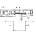
- FIGS. 1 to 4 show a supply and loading device designated as a whole by the reference notation 1 of a reserve pouring tube 2 attached to a movable plate 3, replacing a worn tube 2 ′, attached to a movable plate 3 ', in the service position, and consisting of a main chassis 4 intended to be mounted under a tundish 5 in the vicinity of a tapping hole 7.
- the distributor can possibly already be fitted with a sliding closure. This closure does not constitute an obstacle to the direct fixing of the device 1 according to the invention.
- the shutter is simply a stopper 7 '.
- the pouring tubes 2, 2 ′ each attached to a movable plate 3, 3 ′, slide along a lower plate of the sliding closure device.
- the reference plate 6 along which the supply and loading device 1 slides is a bottom plate of the distributor 5 or of the ladle.
- the movable plate 3, 3 'attached to the pouring tube 2, 2' then serves to seal between the lower nozzle 8 and the reference plate 6 applied against the seat brick 8 'and the sealing collar.
- the reference plate 6 is possibly formed of several independent refractory elements.
- Two guide rails 9, 9 ′ having an inclined stroke relative to the reference plate 6, so as to approach the pouring orifice 7 make it possible to obtain a progressive tightening of the movable plate 3 of a tube of casting 2 against the reference plate 6.
- the upward thrust is obtained by springs 10, 10 ', mounted at a respectable distance from the pouring orifice 7.
- the guide rails 9, 9' are mounted at the end of levers 12, 12 'each subjected to the end opposite to the action of the springs 10, 10' moving the latter away from the enclosure 11 of the container 5.
- the force exerted by the guide rails 9, 9 'on each of the movable plates associated with a pouring tube 2 moving along said rails 9, 9 ′ suspended, increases as they approach the pouring orifice, 7.
- This upward push applies in a manner watertight, the movable plates 3, 3 'of the worn pouring tube 2' and respectively of the reserve tube 2 against the sliding plane of the reference plate 6.
- the slope of the guide rails 9, 9 ' causes the pressure to increase when any one of the pouring tubes 2, 2' approaches the pouring orifice and decreases when it moves away from it, allowing a easy removal of the above-mentioned plate in the standby position 14 away from the tap hole 7.
- the reserve pouring tube 2 pushes the pouring tube into service 2 '.
- the device 1 according to the invention makes it possible to replace a pouring tube 2 ′ in a continuous casting installation, without perceptibly interrupting the pouring jet.
- the used tube 2 ' is loosened and moved away from the pouring zone towards a standby position 14 and the reserve tube 2 is brought simultaneously under the pouring channel.
- the linear displacement of the two pouring tubes 2, 2 ′ can also be carried out using a device of the threaded rod-nut type.
- the assembly of the pouring tube consists of a flat connection which has the property of having an excellent seal and of being able to be easily inertized.
- the supply device is a handling device which makes it possible to supply the reserve tube 2, cast horizontally.
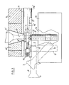
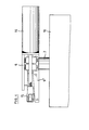
- the plunging end 17 is introduced into a well 18 of an ingot mold 19 by rotating the pouring tube around a substantially horizontal axis.
- the tube is made to slide transversely along the opening of the mold well thanks to the two jacks 16, 16 ′ shown in FIG. 4, so as to align the neck of the pouring tube on the pouring orifice.
- the reference plate 6 is arranged obliquely, so that its slope follows the path of supply of the tubes from their standby position to that of continuous casting.
- An inclined arrangement of the reference plate 6 aims to facilitate the introduction of the plunging end 17 of the tube because it allows the tube to occupy a higher position than if the plate 6 was arranged horizontally.
- This tube is therefore less inclined than if it had been introduced into a conventional supply and exchange device comprising a horizontal reference plate 6.
- An inclined arrangement of the reference plate 6 also makes it possible to reduce the distance between the bottom of the distributor and the mold, without encroaching on the diving height of the tube.
- the casting operation is started as soon as the pouring tube is moved towards the pouring orifice. Under the thrust of the pusher arm 15, a rim of the attached plate 3 of the tube 2 is applied sealingly against the juxtaposed rim of the shutter plate 3 ".
- the added plate 3 forms with the shutter plate 3" a united surface sealingly applied against the reference plate 6. It is therefore sufficient to put the pouring tube in place by sliding under the thrust of the jacks 16, 16 '.
- the closing plate 3 is brought in on the push of a second pusher arm 15 'rigidly fixed to the rods of the double-acting hydraulic cylinders 16,16'.
- the used tube 2 ' is moved towards the position 14 under the thrust of the 3 "blanking plate.
- the used tube 2 ′ is loose and can be easily removed from the supply device and be replaced by a new tube since the pusher arm 15 is retractable.
- the new pouring tube 2 can be quickly put in place under the pouring channel.
- the total duration of the operation for replacing a worn tube 2 'with a new tube is therefore very short. It does not exceed ten seconds for experienced operators. In addition, it can be carried out without being hindered by the other pouring lines connected to the same distributor, since it is carried out in the longitudinal direction, in the extension of the trajectory determined by the rails 9, 9 '.
Landscapes
- Engineering & Computer Science (AREA)
- Mechanical Engineering (AREA)
- Continuous Casting (AREA)
- Casting Devices For Molds (AREA)
Claims (4)
Priority Applications (3)
| Application Number | Priority Date | Filing Date | Title |
|---|---|---|---|
| AT85870180T ATE55715T1 (de) | 1985-01-24 | 1985-12-13 | Vorrichtung zur zufuehrung und auswechselung einer giessduese. |
| FI860310A FI81745C (fi) | 1985-01-24 | 1986-01-22 | Anordning foer att montera och byta ut ett gjutroer. |
| ES551209A ES8700591A1 (es) | 1985-01-24 | 1986-01-24 | Perfeccionamientos en los sistemas conduccion y de cambio de tubos de colada en instalaciones metalurgicas y similares |
Applications Claiming Priority (2)
| Application Number | Priority Date | Filing Date | Title |
|---|---|---|---|
| BE0/214385A BE901564A (fr) | 1985-01-24 | 1985-01-24 | Dispositif d'amenee et d'echange d'un tube de coulee. |
| BE214385 | 1985-01-24 |
Publications (2)
| Publication Number | Publication Date |
|---|---|
| EP0192019A1 EP0192019A1 (de) | 1986-08-27 |
| EP0192019B1 true EP0192019B1 (de) | 1990-08-22 |
Family
ID=3843849
Family Applications (1)
| Application Number | Title | Priority Date | Filing Date |
|---|---|---|---|
| EP85870180A Expired - Lifetime EP0192019B1 (de) | 1985-01-24 | 1985-12-13 | Vorrichtung zur Zuführung und Auswechselung einer Giessdüse |
Country Status (4)
| Country | Link |
|---|---|
| US (1) | US4669528A (de) |
| EP (1) | EP0192019B1 (de) |
| BE (1) | BE901564A (de) |
| DE (1) | DE3579311D1 (de) |
Cited By (12)
| Publication number | Priority date | Publication date | Assignee | Title |
|---|---|---|---|---|
| EP0292925A3 (en) * | 1987-05-29 | 1989-10-11 | Metacon Ag | Device for fixing a dipping nozzle |
| EP0467220A1 (de) * | 1990-07-20 | 1992-01-22 | Didier-Werke Ag | Verfahren und Vorrichtung zur Einführung eines Eintauchausgusses in eine Kokille einer Stranggiessanlage |
| WO1992000821A1 (fr) * | 1990-07-04 | 1992-01-23 | International Industrial Engineering S.A. | Dispositif ameliore d'amenee et d'echange d'un tube de coulee |
| WO1992011105A1 (fr) * | 1990-12-19 | 1992-07-09 | International Industrial Engineering S.A. | Dispositif d'amenee et d'echange d'un tube de coulee |
| US5173199A (en) * | 1990-07-24 | 1992-12-22 | Didier-Werke Ag | Apparatus for use in replacing a worn pouring pipe and for adjusting molten metal flow through a pouring pipe |
| BE1006191A3 (fr) * | 1992-09-30 | 1994-06-07 | Int Ind Eng Sa | Bras-pousseur eclipsable d'un dispositif d'amenee et d'echange de tubes de coulee. |
| US5693249A (en) * | 1993-07-27 | 1997-12-02 | International Industrial Engineering S.A. | Device for supplying and replacing pouring tubes in a continuous casting plant |
| FR2760667A1 (fr) * | 1997-03-14 | 1998-09-18 | Int Ind Eng Sa | Dispositif obturateur-regulateur de coulee continue a chaud, avec echangeur de busette perfectionne |
| US5984153A (en) * | 1995-05-05 | 1999-11-16 | Vesuvius France | Device and process for changing a continuous casting tube of a distributor of a steel mill |
| AU731336B2 (en) * | 1996-02-22 | 2001-03-29 | Vesuvius France S.A. | Tundish equipped with a tube changer and plate for the tube changer |
| WO2011047850A1 (en) | 2009-10-21 | 2011-04-28 | Vesuvius Group S.A. | Pouring nozzle and assembly of such a pouring nozzle with an inner nozzle |
| EP1590114B2 (de) † | 2003-01-20 | 2011-10-26 | Vesuvius Group S.A | Giessdüse, drückvorrichtung für eine giessdüse und giessanlage |
Families Citing this family (15)
| Publication number | Priority date | Publication date | Assignee | Title |
|---|---|---|---|---|
| JP3162535B2 (ja) | 1993-04-12 | 2001-05-08 | 新日本製鐵株式会社 | 連続鋳造設備における浸漬ノズル交換装置 |
| BE1008438A3 (fr) * | 1994-06-23 | 1996-05-07 | Int Ind Eng Sa | Tube de coulee assemble a une plaque rapportee par une enveloppe metallique. |
| WO1997038809A1 (de) * | 1996-04-12 | 1997-10-23 | Stopinc Ag | Verfahren zum wechseln eines giessrohrs am ausguss eines metallschmelze enthaltenden gefässes |
| JP3108372B2 (ja) * | 1996-11-15 | 2000-11-13 | 品川白煉瓦株式会社 | 浸漬ノズルの接合方法 |
| KR19980070518A (ko) * | 1997-01-17 | 1998-10-26 | 오자와미또시 | 침지노즐 교환장치를 구비한 슬래브용 연속주조기 및침지노즐의 교환방법 |
| US5866022A (en) * | 1997-03-24 | 1999-02-02 | North American Refractories Company | Refractory pour tube with cast plate |
| BE1013024A3 (fr) | 1998-12-15 | 2001-08-07 | Internat Ind Engineering S A | Tube de coulee. |
| JP2006508804A (ja) * | 2002-12-10 | 2006-03-16 | ベスビウス グループ ソシエテ アノニム | スライデイングプレート式流れ制御装置を組み込んだ鋳造設備のノズル挿入及び/または除去装置用の耐火性プレート |
| US7191819B2 (en) * | 2004-12-07 | 2007-03-20 | Nucor Corporation | Continuously casting steel strip |
| JP4669888B2 (ja) * | 2008-01-16 | 2011-04-13 | 品川リフラクトリーズ株式会社 | 浸漬ノズル支持交換機構 |
| US8602085B2 (en) * | 2010-03-19 | 2013-12-10 | Vesuvius Group S.A. | Device with detector for holding and replacing a casting plate |
| EP2368655A1 (de) | 2010-03-19 | 2011-09-28 | Vesuvius Group S.A | Platte für den Transfer von flüssigem Metall aus einem metallurgischen Behälter sowie Gestell und Wechselvorrichtung für eine solche Platte |
| EP2371471A1 (de) * | 2010-03-19 | 2011-10-05 | Vesuvius Group S.A | Interne Düse für den Transfer von flüssigem Metall in einem Behälter, Einspannsystem für diese Düse und Ausflussvorrichtung |
| EP2368654A1 (de) | 2010-03-19 | 2011-09-28 | Vesuvius Group S.A | Halte- und Wechselvorrichtung einer Gespannplatte in einer Gießanlage, Metallmantel der Gespannplatte und Gespannplatte, die mit Mitteln zum Anschluss an einen Sensor der Vorrichtung ausgestattet ist |
| ES2697023T3 (es) | 2010-03-30 | 2019-01-21 | Akechi Ceram Co Ltd | Buza de colada |
Family Cites Families (11)
| Publication number | Priority date | Publication date | Assignee | Title |
|---|---|---|---|---|
| US3578062A (en) * | 1968-03-05 | 1971-05-11 | Nippon Kokan Kk | Method of and apparatus for continuous casting with immersion-type long nozzles |
| US3613965A (en) * | 1969-06-25 | 1971-10-19 | United States Steel Corp | Operating and loading mechanism for slidable gates |
| US3907022A (en) * | 1969-10-30 | 1975-09-23 | Schloemann Siemag Ag | Method of handling and replacing pouring tubes of a continuous casting apparatus |
| DE2027881B2 (de) * | 1970-06-06 | 1979-12-13 | Schloemann-Siemag Ag, 4000 Duesseldorf | Vorrichtung zur Erneuerung der Stahlzuführung vom Zwischenbehälter zur Kokille einer Stranggießanlage |
| US3743007A (en) * | 1970-10-21 | 1973-07-03 | Schloemann Ag | Continuous casting apparatus with inter-changeable pouring tubes |
| US3727805A (en) * | 1972-01-24 | 1973-04-17 | Steel Corp | Mechanism for supporting a submerged pouring tube on a bottom-pour vessel and method of replacing tubes |
| US3749387A (en) * | 1972-03-16 | 1973-07-31 | United States Steel Corp | Method and device for shrouding a stream of metal teemed through a slidable gate |
| US3730401A (en) * | 1972-03-22 | 1973-05-01 | Steel Corp | Apparatus for supporting and operating a slidable gate and extended tube nozzle on a bottom-pour vessel |
| CH598888A5 (de) * | 1976-03-09 | 1978-05-12 | Concast Ag | |
| GB1597215A (en) * | 1978-04-24 | 1981-09-03 | Vesuvius Int Corp | Device for replacing pouring tubes |
| FR2486428A1 (fr) * | 1980-07-11 | 1982-01-15 | Fives Cail Babcock | Dispositif pour mettre en place un tube de coulee sur une poche de coulee |
-
1985
- 1985-01-24 BE BE0/214385A patent/BE901564A/fr not_active IP Right Cessation
- 1985-12-13 EP EP85870180A patent/EP0192019B1/de not_active Expired - Lifetime
- 1985-12-13 DE DE8585870180T patent/DE3579311D1/de not_active Expired - Fee Related
-
1986
- 1986-01-22 US US06/821,191 patent/US4669528A/en not_active Expired - Lifetime
Cited By (21)
| Publication number | Priority date | Publication date | Assignee | Title |
|---|---|---|---|---|
| EP0292925A3 (en) * | 1987-05-29 | 1989-10-11 | Metacon Ag | Device for fixing a dipping nozzle |
| US5351865A (en) * | 1990-07-04 | 1994-10-04 | International Industrial Engineering S.A. | Apparatus for the conveying and exchanging of a pouring tube |
| WO1992000821A1 (fr) * | 1990-07-04 | 1992-01-23 | International Industrial Engineering S.A. | Dispositif ameliore d'amenee et d'echange d'un tube de coulee |
| WO1992000822A1 (fr) * | 1990-07-04 | 1992-01-23 | International Industrial Engineering S.A. | Dispositif d'amenee et d'echange d'un tube de coulee |
| TR25322A (tr) * | 1990-07-04 | 1993-01-01 | Int Ind Eng Sa | BIR DÖKüM BORUSUNUN ALIP VERME VE SEVKIYAT TERTIBATINDA ISLAHAT |
| EP0467220A1 (de) * | 1990-07-20 | 1992-01-22 | Didier-Werke Ag | Verfahren und Vorrichtung zur Einführung eines Eintauchausgusses in eine Kokille einer Stranggiessanlage |
| US5180536A (en) * | 1990-07-20 | 1993-01-19 | Didier-Weke Ag | Method and apparatus for inserting a pouring pipe into a mold of a continuous casting machine |
| US5173199A (en) * | 1990-07-24 | 1992-12-22 | Didier-Werke Ag | Apparatus for use in replacing a worn pouring pipe and for adjusting molten metal flow through a pouring pipe |
| WO1992011105A1 (fr) * | 1990-12-19 | 1992-07-09 | International Industrial Engineering S.A. | Dispositif d'amenee et d'echange d'un tube de coulee |
| BE1004092A3 (fr) * | 1990-12-19 | 1992-09-22 | Internat Ind Engineering S A | Dispositif d'amenee et d'echange d'un tube de coulee. |
| TR25588A (tr) * | 1990-12-19 | 1993-07-01 | Int Ind Eng Sa | BIR DÖKüM BORUSUNUN BESLENMESI VE DEGISTIRILMESI ICIN CIHAZ |
| BE1006191A3 (fr) * | 1992-09-30 | 1994-06-07 | Int Ind Eng Sa | Bras-pousseur eclipsable d'un dispositif d'amenee et d'echange de tubes de coulee. |
| US5693249A (en) * | 1993-07-27 | 1997-12-02 | International Industrial Engineering S.A. | Device for supplying and replacing pouring tubes in a continuous casting plant |
| US5984153A (en) * | 1995-05-05 | 1999-11-16 | Vesuvius France | Device and process for changing a continuous casting tube of a distributor of a steel mill |
| AU731336B2 (en) * | 1996-02-22 | 2001-03-29 | Vesuvius France S.A. | Tundish equipped with a tube changer and plate for the tube changer |
| FR2760667A1 (fr) * | 1997-03-14 | 1998-09-18 | Int Ind Eng Sa | Dispositif obturateur-regulateur de coulee continue a chaud, avec echangeur de busette perfectionne |
| WO1998041344A1 (fr) * | 1997-03-14 | 1998-09-24 | Vesuvius Group S.A. | Dispositif obturateur-regulateur de coulee continue a chaud, avec echangeur de busette perfectionne |
| EP1590114B2 (de) † | 2003-01-20 | 2011-10-26 | Vesuvius Group S.A | Giessdüse, drückvorrichtung für eine giessdüse und giessanlage |
| WO2011047850A1 (en) | 2009-10-21 | 2011-04-28 | Vesuvius Group S.A. | Pouring nozzle and assembly of such a pouring nozzle with an inner nozzle |
| EP2319640A1 (de) | 2009-10-21 | 2011-05-11 | Vesuvius Group S.A | Tauschgiessrohr für Metallschmelze sowie Zusammensetzung dessen mit einer Ausgussdüse |
| US8905274B2 (en) | 2009-10-21 | 2014-12-09 | Vesuvius Group S.A. | Pouring nozzle and assembly of such a pouring nozzle with an inner nozzle |
Also Published As
| Publication number | Publication date |
|---|---|
| EP0192019A1 (de) | 1986-08-27 |
| DE3579311D1 (de) | 1990-09-27 |
| US4669528A (en) | 1987-06-02 |
| BE901564A (fr) | 1985-07-24 |
Similar Documents
| Publication | Publication Date | Title |
|---|---|---|
| EP0192019B1 (de) | Vorrichtung zur Zuführung und Auswechselung einer Giessdüse | |
| EP0537195B1 (de) | Zufuhr- und austauschvorrichtung eines tauchrohres | |
| FR2535835A1 (fr) | Four a arc basculant | |
| EP0714332B1 (de) | Vorrichtung zum einführung und austausch eines tauchrohres in eine stranggiessvorrichtung zum giessen von dünnen brammen | |
| EP0230180B1 (de) | Verfahren und Vorrichtung zum Unterhalten der Auskleidung eines Ofengefässes | |
| EP0734458B1 (de) | Vorrichtung zum beschicken eines elektrofens mit flüssigmetall | |
| FR2551374A1 (fr) | Dispositif pour plaques refractaires d'obturateurs coulissants | |
| FR2580206A1 (fr) | Obturateur a tiroir pour recipients metallurgiques | |
| EP0122904A2 (de) | Schieberverschluss für Behälter in der Stahl-Eisen Industrie oder Metallurgie | |
| EP0563072B1 (de) | Vorrichtung zur heranführung und zum austausch eines giessrohres | |
| BE1008394A6 (fr) | Dispositif de raccordement et d'echange d'un tube de coulee sur un recipient contenant un metal en fusion. | |
| EP0646053B1 (de) | Vorrichtung zur durchflussregelung eines flüssigen metallstromes | |
| BE896223A (fr) | Dispositif de fermeture coulissant pour conteneur siderurgique ou metallurgique | |
| FR2655282A1 (fr) | Dispositif de raccordement d'un tube de coulee a la busette de coulee d'un recipient contenant du metal en fusion. | |
| EP0501173A1 (de) | Verfahren und Vorrichtung zum Behandeln von Stahlwerks-Schlacken | |
| FR2716819A1 (fr) | Procédé et dispositif de coulée. | |
| FR2685653A1 (fr) | Dispositif de refection du revetement interieur d'un trou de coulee notamment d'un convertisseur d'acierie. | |
| EP0537536B1 (de) | Vorrichtung zum automatischen Ankuppeln von Versorgungsleitungen an ein metallurgisches Gefäss | |
| BE1006191A3 (fr) | Bras-pousseur eclipsable d'un dispositif d'amenee et d'echange de tubes de coulee. | |
| EP0498684B1 (de) | Ausstosseinrichtung für eine Giessschutzrohr-Trageinrichtung in eine Stranggiessvorrichtung | |
| EP0455619A1 (de) | Vorrichtung zum Metallgiessen und Verfahren zum Betrieb derselben | |
| BE1005416A6 (fr) | Dispositif pour le nettoyage d'un tube de poche. | |
| LU83061A1 (fr) | Perfectionnement aux dispositifs de coulee d'acier liquide | |
| LU88440A1 (fr) | Dispositif de chargement d'un four électrique | |
| BE691504A (de) |
Legal Events
| Date | Code | Title | Description |
|---|---|---|---|
| PUAI | Public reference made under article 153(3) epc to a published international application that has entered the european phase |
Free format text: ORIGINAL CODE: 0009012 |
|
| AK | Designated contracting states |
Kind code of ref document: A1 Designated state(s): AT BE DE FR GB IT LU SE |
|
| 17P | Request for examination filed |
Effective date: 19870211 |
|
| 17Q | First examination report despatched |
Effective date: 19881222 |
|
| GRAA | (expected) grant |
Free format text: ORIGINAL CODE: 0009210 |
|
| ITF | It: translation for a ep patent filed | ||
| AK | Designated contracting states |
Kind code of ref document: B1 Designated state(s): AT BE DE FR GB IT LU SE |
|
| REF | Corresponds to: |
Ref document number: 55715 Country of ref document: AT Date of ref document: 19900915 Kind code of ref document: T |
|
| GBT | Gb: translation of ep patent filed (gb section 77(6)(a)/1977) | ||
| REF | Corresponds to: |
Ref document number: 3579311 Country of ref document: DE Date of ref document: 19900927 |
|
| PLBI | Opposition filed |
Free format text: ORIGINAL CODE: 0009260 |
|
| 26 | Opposition filed |
Opponent name: DIDIER-WERKE AG Effective date: 19910522 |
|
| ITTA | It: last paid annual fee | ||
| EPTA | Lu: last paid annual fee | ||
| EAL | Se: european patent in force in sweden |
Ref document number: 85870180.8 |
|
| APAC | Appeal dossier modified |
Free format text: ORIGINAL CODE: EPIDOS NOAPO |
|
| PLBN | Opposition rejected |
Free format text: ORIGINAL CODE: 0009273 |
|
| STAA | Information on the status of an ep patent application or granted ep patent |
Free format text: STATUS: OPPOSITION REJECTED |
|
| 27O | Opposition rejected |
Effective date: 19960305 |
|
| GBCC | Gb: corrected translation (of claims) filed (gb section 80(3)/1977) | ||
| REG | Reference to a national code |
Ref country code: GB Ref legal event code: IF02 |
|
| PGFP | Annual fee paid to national office [announced via postgrant information from national office to epo] |
Ref country code: LU Payment date: 20021129 Year of fee payment: 18 |
|
| PGFP | Annual fee paid to national office [announced via postgrant information from national office to epo] |
Ref country code: AT Payment date: 20031121 Year of fee payment: 19 |
|
| PGFP | Annual fee paid to national office [announced via postgrant information from national office to epo] |
Ref country code: GB Payment date: 20031210 Year of fee payment: 19 |
|
| PG25 | Lapsed in a contracting state [announced via postgrant information from national office to epo] |
Ref country code: LU Free format text: LAPSE BECAUSE OF NON-PAYMENT OF DUE FEES Effective date: 20031213 |
|
| PGFP | Annual fee paid to national office [announced via postgrant information from national office to epo] |
Ref country code: FR Payment date: 20031218 Year of fee payment: 19 |
|
| PGFP | Annual fee paid to national office [announced via postgrant information from national office to epo] |
Ref country code: SE Payment date: 20031219 Year of fee payment: 19 |
|
| PGFP | Annual fee paid to national office [announced via postgrant information from national office to epo] |
Ref country code: BE Payment date: 20040116 Year of fee payment: 19 |
|
| PGFP | Annual fee paid to national office [announced via postgrant information from national office to epo] |
Ref country code: DE Payment date: 20040202 Year of fee payment: 19 |
|
| PG25 | Lapsed in a contracting state [announced via postgrant information from national office to epo] |
Ref country code: GB Free format text: LAPSE BECAUSE OF NON-PAYMENT OF DUE FEES Effective date: 20041213 Ref country code: AT Free format text: LAPSE BECAUSE OF NON-PAYMENT OF DUE FEES Effective date: 20041213 |
|
| PG25 | Lapsed in a contracting state [announced via postgrant information from national office to epo] |
Ref country code: SE Free format text: LAPSE BECAUSE OF NON-PAYMENT OF DUE FEES Effective date: 20041214 |
|
| PG25 | Lapsed in a contracting state [announced via postgrant information from national office to epo] |
Ref country code: BE Free format text: LAPSE BECAUSE OF NON-PAYMENT OF DUE FEES Effective date: 20041231 |
|
| BERE | Be: lapsed |
Owner name: *INTERNATIONAL INDUSTRIAL ENGINEERING S.P.R.L. Effective date: 20041231 |
|
| PG25 | Lapsed in a contracting state [announced via postgrant information from national office to epo] |
Ref country code: DE Free format text: LAPSE BECAUSE OF NON-PAYMENT OF DUE FEES Effective date: 20050701 |
|
| EUG | Se: european patent has lapsed | ||
| GBPC | Gb: european patent ceased through non-payment of renewal fee |
Effective date: 20041213 |
|
| PG25 | Lapsed in a contracting state [announced via postgrant information from national office to epo] |
Ref country code: FR Free format text: LAPSE BECAUSE OF NON-PAYMENT OF DUE FEES Effective date: 20050831 |
|
| APAH | Appeal reference modified |
Free format text: ORIGINAL CODE: EPIDOSCREFNO |
|
| REG | Reference to a national code |
Ref country code: FR Ref legal event code: ST |
|
| BERE | Be: lapsed |
Owner name: *INTERNATIONAL INDUSTRIAL ENGINEERING S.P.R.L. Effective date: 20041231 |