EP0192101A1 - Débitmètre massique - Google Patents
Débitmètre massique Download PDFInfo
- Publication number
- EP0192101A1 EP0192101A1 EP86101265A EP86101265A EP0192101A1 EP 0192101 A1 EP0192101 A1 EP 0192101A1 EP 86101265 A EP86101265 A EP 86101265A EP 86101265 A EP86101265 A EP 86101265A EP 0192101 A1 EP0192101 A1 EP 0192101A1
- Authority
- EP
- European Patent Office
- Prior art keywords
- housing
- mass flow
- flow meter
- conduit
- transducer
- Prior art date
- Legal status (The legal status is an assumption and is not a legal conclusion. Google has not performed a legal analysis and makes no representation as to the accuracy of the status listed.)
- Withdrawn
Links
- 239000000463 material Substances 0.000 claims abstract description 40
- 238000005259 measurement Methods 0.000 claims description 4
- 239000012528 membrane Substances 0.000 claims description 2
- 230000008602 contraction Effects 0.000 description 4
- 239000012530 fluid Substances 0.000 description 3
- 230000001419 dependent effect Effects 0.000 description 2
- 238000000034 method Methods 0.000 description 2
- 238000004891 communication Methods 0.000 description 1
- 230000001186 cumulative effect Effects 0.000 description 1
- 239000007788 liquid Substances 0.000 description 1
- 229910052751 metal Inorganic materials 0.000 description 1
- 239000002184 metal Substances 0.000 description 1
- 150000002739 metals Chemical class 0.000 description 1
- 238000005192 partition Methods 0.000 description 1
Images


Classifications
-
- G—PHYSICS
- G01—MEASURING; TESTING
- G01F—MEASURING VOLUME, VOLUME FLOW, MASS FLOW OR LIQUID LEVEL; METERING BY VOLUME
- G01F1/00—Measuring the volume flow or mass flow of fluid or fluent solid material wherein the fluid passes through a meter in a continuous flow
- G01F1/76—Devices for measuring mass flow of a fluid or a fluent solid material
- G01F1/78—Direct mass flowmeters
-
- G—PHYSICS
- G01—MEASURING; TESTING
- G01F—MEASURING VOLUME, VOLUME FLOW, MASS FLOW OR LIQUID LEVEL; METERING BY VOLUME
- G01F1/00—Measuring the volume flow or mass flow of fluid or fluent solid material wherein the fluid passes through a meter in a continuous flow
- G01F1/05—Measuring the volume flow or mass flow of fluid or fluent solid material wherein the fluid passes through a meter in a continuous flow by using mechanical effects
- G01F1/20—Measuring the volume flow or mass flow of fluid or fluent solid material wherein the fluid passes through a meter in a continuous flow by using mechanical effects by detection of dynamic effects of the flow
- G01F1/206—Measuring pressure, force or momentum of a fluid flow which is forced to change its direction
Definitions
- One prior proposed mass flow meter imparts an angular velocity to a previously linearly flowing fluid, and then measures the resultant angular momentum to provide a signal that is representative of the mass flow rate.
- an impeller comprising a suitable rotor or turbine.
- U.S.A. Patent Specification No. 3164019 discloses a mass flow measuring device which comprises a substantially "S" shaped insert flexibly coupled into a pipe wherein a fluid, the mass flow of which is to be measured, is caused to flow.
- the flow through the 'S" shaped insert generates a torque about an axis passing through the point of symmetry of the "S". This is measured with a spring which resists any movement of the insert.
- the spring is connected to a torque motor which is responsive to signals from a synchro connected to a pivot which pivotally supports the insert.
- a closed loop servo which resists the torque generated in the 'S" shaped insert, maintaining the insert at a mull position, whilst measuring the torque. Since the inlet and the outlet to 'S" shaped insert are offset, if the insert expands or contracts, for example as a result of thermal expansion or contraction, an error can arise.
- a mass flow meter comprising a flow passage through which the material, the mass flow of which is to be measured, is constrained to pass, the flow passage defining a substantially linear inlet port, and a substantially linear outlet port, a further part of the flow passage being defined by an element of the apparatus that is located for pivoting about a predetermined pivot axis, said element defining a flow path portion having a bend in one sense and a bend in the opposite sense, said bends being located symmetrically about said pivot axis so that, as material flows through the device a velocity force is applied to said element tending to rotate that element about said axis, a force measuring means being provided to measure the velocity force applied to said element, the force measuring means being of the type that can measure force without the operative parts thereof being moved by a significant extent, the inlet port and the outlet port being substantially coaxially aligned.
- the force measuring means comprise a transducer, such as a gyroscopic transducer, or on oscillating wire transducer.
- the arrangement is symmetrical about the said axis of rot at ion.
- said element comprises substantially spherical housing, the said flow being adapted to follow said flow path within the confines of the spherical housing.
- the spherical housing comprises an inlet associated with a conduit portion directing the flow into the spherical housing in one direction, and an axially aligned outlet associated with a conduit portion directing the outflow from the housing in another direction which is not aligned with said one direction so that the material flowing through the housing follows said flow path, the axis of rotation of the housing being perpendicular to overall direction of flow of material through the mass flow meter.
- the housing has an open hollow centre, said conduit portions being located at diametrically opposed positions.
- the housing defines two chambers, one connecting with the inlet port and one connecting with the outlet port, therebeing at least two flow passages interconnecting the chamber connected to the inlet port with the chamber connecting to the outlet port, the passages being located on opposite sides of the axis defined by the inlet port and the outlet port, the passages being curved in opposite senses when viewed from the same direction so that as material flows from the chamber connecting the inlet conduit to the chamber connecting to the outlet conduit a moment is applied to the housing tending to rotate the housing, the housing being mounted so that it can rotate at least to a limited extent about the axis defined by the inlet and outlet ports.
- the housing is formed of two identical halves which are bolted or otherwise secured together.
- the density of the steam being metred is measured at a point remote from the 'S shaped insert. Where density and flow rate both fluctuate that can lead to errors arising since it is not possible to determine the density of the particular sample that applied any specific measured velocity force.
- Advantageously means are provided to measure the density of the contents of said element simultaneously with the measurement of said velocity force applied to the element. Since the volume of the element is known, and the tore mass of the element is known, the total mass of the elements and contents may be determined, from which the density may be directly calculated.
- the said element comprises a length of conduit of substantially "S" configuration, which is mounted within a housing, the housing being partitioned to form two chambers, one connected with the inlet and the other connected with the outlet, the section of conduit serving to interconnect the said chambers.
- said chambers are partitioned by a relatively flexible membrane which assists in supporting the said length of conduit in position.
- each transducer is a transducer of the type that operates without any significant movement of the operative parts thereof.
- the transducer may be considered to be a "hard” transducer having an operative stroke that can be measured in microns (e.g. 10 microns) as compared with a conventional "soft" transducer which may have an operating stroke that can be measured in millimetres.
- the transducer may comprise an oscillating wire transducer (in which the force applied to the transducer adjusts the tension present in a wire which is caused to vibrate, the vibrating or resonant or frequency of the wire being measured to determine the force applied to the transducer) or a gyroscopic transducer (in which the force applied to the transducer is caused to move one of the bearings supporting a gyroscope, the subsequent precessing of the gyroscope being indicative of the force applied).
- an oscillating wire transducer in which the force applied to the transducer adjusts the tension present in a wire which is caused to vibrate, the vibrating or resonant or frequency of the wire being measured to determine the force applied to the transducer
- a gyroscopic transducer in which the force applied to the transducer is caused to move one of the bearings supporting a gyroscope, the subsequent precessing of the gyroscope being indicative of the force applied.
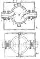
- an outer housing is provided, but the housing only serves the function of maintaining the inlet conduit 2 and the outlet conduit 3 in precisely determined positions.
- the inlet conduit and the outlet conduit are aligned, and are thus co-axial.
- the inlet conduit 2 is connected by means of a flexible pipe portion 4 to an inlet port 5 provided on a symmetrical spherical inner housing 6.
- the inlet port 5 of the inner housing 6 is connected to an interior stub conduit 7 which directs the flow of material entering the inner housing 6 upwardly tangentially adjacent the interior surface of the spherical inner housing 6.
- the spherical inner housing 6 is mounted on horizontal trunions 8 for pivoting about a horizontal pivot axis 9.
- the housing is actually fabricated from two identical halves 11, that are bolted together by means of bolts 12.
- the spherical inner housing 6 defines an outlet port 13 which is axially aligned with the inlet port 5.
- the outlet port is associated with a stub conduit 14 located on the interior of the spherical inner housing 6, this stub conduit extending downwardly substantially tangentially with the interior of the lower part of the spherical inner housing 6.
- the stub conduits 7 and 14 are diametrically opposed.
- the outlet port 13 of the spherical inner housing 6 is connected by a flexible pipe portion 15 to the outlet conduit 3 of the entire flow meter.
- a force measuring transducer 16 is provided, of the type described above and a connecting rod 17 extends between part of the inner housing 6 and the transducer 16 so that any force tending to rotate the inner housing 6 about the axis defined by the trunnions may be detected by the transudcer 16.
- flow dividing webs 18 may be provided on the interior of the housing associated with the stub conduits 7, 14.
- Figure 2 the open mouths of the stub conduits 7, 14 are shown in . phantom and the webs 18 are also illustrated in a similar manner.
- the transducer is thermally insulated from the housing, for example by providing a thermal break in the connecting rod.
- Temperature compensation may be achieved by providing a connecting rod having a selected coefficient of expansion such that as the configuration of the housing is changed, due to expansion or contraction upon a change in ambient temperature, a precisely compensating change occurs in the configuration of the connecting rod.
- the connecting rod may conveniently be formed from metals having different coefficients of expansion.
- the material flowing through the described device is first constrained to change direction in one sense and is then constrained to change direction in the other sense, the points at which the change of direction of flow is effected being located in a symmetrical way on opposite sides of an axis of rotation, the resultant velocity force tending to rotate the housing about that axis subsequently being measured.
- the velocity force that tends to rotate the housing is generated since when any material flowing through the housing turns a corner, a force is applied to the housing which is dependent upon the density i.e. the mass of the materiat flowing through the conduit, and the square of the velocity.
- the resultant force causes a moment about the horizontal axis 9, and this force tends to cause the housing to rotate about the horizontal axis 9.
- the connection rod 17, extends between the housing and the transducer 16, this rotation of the housing is resisted, and thus the housing remains subtantially stationary.
- the velocity force tending to rotate the housing can be measured by the transducer 16, this force being indicative of the density or mass of material flowing through the conduit.
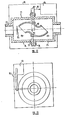
- FIGS 3 and 4 illustrate an alternative embodiment of the invention which operates on the same principle as the embodiment illustrated in Figure 2.
- this embodiment of the invention incorporates a spherical housing 20 which corresponds to the spherical housing 6 of the first described embodiment of the invention.
- the housing 20 is mounted in position by means of an inlet pipe 21 and an outlet pipe 22, the inlet and outlet pipes being mounted, by means of appropriate "0" rings 23, 24 in inlet and outlet apertures formed in the spherical housing 20.
- the inlets are associated with short stub pipes 24, 25, corresponding to the stub pipes of the first described embodiment.
- the pipes 21, 22 are mounted by means of further “O" rings (only one of which, 25, is shown) in a housing 26.
- the arrangement is such that the spherical housing 20 is pivotally mounted for rotation about an axis 27 and can rotate slightly about that axis due to the freedom of movement provided to the spherical housing 20 by virtue of the way it is mounted in position by means of the pipes 21, 22 and the associated "0" rings.
- one of the trunnions 28 by means of which the spherical chamber 20 is mounted for rotation about the axis 27 is actually inserted through an aperture formed in a lever 29.
- One end, 30, of the lever 29 is pivotally connected by means of a pivot pin 31, to one wall of the housing 26.
- the other end 32 of the lever is adapted to provide a force to a density force sensing transducer 33.
- the mass of the spherical housing 20 will tend to cause the trunnion 28 to move downwardly, thus causing lever 29 to pivot in a downward manner about the pivotal connection 31, thus forcing the end 32 of the lever downwardly on to the force sensing transducer 33.
- the density force sensing transducer can thus provide an output signal representative of the mass of (or density of the contents of) the spherical housing 20.
- the effective mass of the spherical housing 20 will depend upon the weight of material present within the housing at any point in time, and since the volume of the housing is known the output from the transducer 33 may be calibrated in mass or in density. Consequently it will be appreciated that the embodiment described in Figures 3 and 4 can provide an indication of the mass of, and density of, material flowing through the chamber 20.
- a velocity transducer corresponding to the transducer 16 will be provided to measure the rotational force applied to the spherical chamber 20 by means of the material flowing therethrough, and thus the apparatus shown in Figures 3 and 4 can provide detailed information concerning the density, and the mass flow rate, of material flowing through the spherical chamber 20.
- Figures 3 and 4 measures the density of a sample being measured and the turning force generated by that sample simultaneously. This provides a more accurate result than obtainable with prior proposed devices in which the density of a flowing stream is measured at one point, and a turning moment generated by the velocity force of the stream is measured at another point.
- the material flowing through the described device is first constrained to change direction in one sense and is then constrained to change direction in the other sense, the points at which the change of direction of flow is effected being located in a symmetrical way on opposite sides of an axis of rotation, the resultant force tending to rotate the housing about that axis subsequently being measured.
- FIG. 5 to 9 illustrate another embodiment of the invention.
- An outer housing 40 contains an inner housing 41, the exterior of which is of generally spherical configuration.
- the outer housing 41 is formed of two identical halves 42, 43 which are bolted together by bolts 44 passing through coaligned apertures in protruding flanges formed on the housing halve 42, 43.
- the housing half 42 defines on inlet port 45 which passes through one exterior wall of the housing 40, and the housing half 41 defines an outlet port 46, axially aligned to the inlet port 45, which passes through the other side of the housing.
- the inner housing 41 is mounted for rotation about the axis defined by the inlet port 45 and the outlet port 46. Part of the periphery of the housing is connected by means of an appropriate connecting rod 47 to a transducer 48 of the "hard" type os described above.
- the two housing parts 42, 43 define respective chambers 49, 50 which are substantially sealed from each other.
- two flow passages are provided which interconnect the chambers 49, 50.
- one communication passage is located adjacent the top of the inner housing 41 and is located adjacent the shell of. the housing.
- a channel 5 that forms the flow passage is configured to be of a substantially "U" configuration, the two arms of the "U” being parallel with and on either side of the central partition which separates the chambers 49 and 50. It will be appreciated that a flow of material passing through the 'U" shaped channel will impart a force F' to the housing as indicated by the arrow 52.
- Another identical channel 53 is located on the opposite side of the pivot axis defined by the inlet port 45 and the outlet port 46 and comprises a similar configured "U” channel, but having (when viewed in plan), the opposite sense.
- the force F" indicated by the arrow 54 exerted on the housing when material flows through the flow meter cooperates with the force indicated by the arrow 52 to create a moment, proportional to the velocity force, tending to rotate the inner housing 41 about the pivot axis defined by the inlet port 45 and the out let port 46.
- the force actually applied to the inner housing is measured by the transducer 48 which is of the "hard” type, as described above.
- the transducer 48 which is of the "hard” type, as described above.
- FIG. 10 a further embodiment of the invention is shown which corresponds broadly to the embodiment of Figures 5 to 9, although it will be noted that the spherical chamber 61 of the embodiment shown in Figures 10 and I I is of a slightly different design to the spherical chamber 41 of the embodiment of Figures 5 to 9. However, the differences are not sufficient to warrant detailed description at this stage. It will be noted that, in the embodiment illustrated in Figures 10 to 11 the housing 61 carries a protruding arm 62 adapted to engage a force sensing transducer 63 which corresponds to the transducer 48 of the embodiment of Figures 5 to 9.
- the spherical housing 61 is mounted in position by means of three rollers 64, 65, 66 to permit the housing 61 to rotate about the axis defined by the inlet pipe 67 and the outlet pipe 68 which are connected appropriately to the housing 61.
- the lowermost roller 66 is mounted on a force measuring transducer 67 which is of the 'hard" type described above.
- the transducer 67 is thus adapted to provide an output signal representative of the mass of the chamber 61 and the contents thereof. It will be appreciated, therefore, that the embodiments shown in Figures 10 and 11 may be used not only to measure the mass flow rate of material passing through the chamber 61, but may also be used to measure the instantaneous mass present within the chamber 61, thus enabling the density of the material to be calculated.
- the embodiment of Figures 3 and 4 may also be used in this way.
- the inlet and outlet conduits are axially co-aligned, and this serves to minimise any errors that may be introduced to the apparatus if, for example, the pressure (and thus in some cases the density) of material entering on one side of the mass flow meter is less than the pressure of the material leaving the other side of the mass flow meter.
- the co- alignment of the inlet and outlet ports reduces the risk of any errors arising due to temperature differentials present in the apparatus. If the inlet and outlet were not aligned, but were offset, if the temperature of the apparatus varies, due to thermal expansion and contraction, an error would be introduced. However, with the inlet and outlet coaligned thermal expansion and contraction of the components of the mass flow meter does not cause the inlet and the outlet to be misaligned.
- an outer housing 70 is provided, but this outer housing is optional.
- the outer housing contains an inner housing 71 of generally rectangular configuration which defines an axial inlet port 72 and, at the opposite end thereof an axial outlet port 73.
- the inlet and outlet ports are co-aligned, as in the earlier described embodiments of the invention.
- the housing is actually formed of two identical elements 74, 75 which are connected together by means of bolts 76 passing through appropriate flanges provided on the elements 74, 75.
- a slightly resilient diaphragm 77 is provided which is trapped between the housing halves and which serves to divide the interior of the housing into two separate chambers, namely a first chamber 78 communicating with the inlet port 72 and a second chamber 79 communicating with the outlet port 73.
- a substantially “S" sectioned length of conduit 80 is sealingly mounted on the diaphragm 77 and is also mounted for rotation about an axle 81 which can be seen most clearly in Figure 14.
- One end of the axle 81 is connected to a lever 82, the end of which is connected by means of a connecting rod 83 to a transducer 84 of the "hard" type as described above.
- a baffle 85 may be provided within the chamber 78 coaligned with the inlet port 72, if desired.
- a material, the mass flow of which is to be measured, may be introduced to the described apparatus through the inlet port 72.
- the material will then flow through the "S" shaped channel defined by the "S" configured section of conduit 80 which is symmetrical relative to the axis 81 of rotation thereof.
- the material flowing through the conduit 80 is thus constrained to change direction in one sense on one side of the pivot axle 81 and to change direction in the opposite sense on the other side of the pivot axle 81.
- the section of conduit 80 has a moment of force applied thereto, proportional to the velocity force, tending to rotate the section of conduit 80 about the axle 81.
- This rotational force is measured by means of the transducer 84. Since the transducer 84 is a 'hard" transducer the conduit 80 does not actually rotate to any significant extent, but nevertheless the force tending to rotate the conduit is still measured. This force is representative of the mass flow.
- the force measuring transducer or transducers may be connected to an appropriately programmed microprocessor or computer which will provide an output indication of the value of the specific parameter being measured.
Landscapes
- Physics & Mathematics (AREA)
- Fluid Mechanics (AREA)
- General Physics & Mathematics (AREA)
- Measuring Volume Flow (AREA)
Applications Claiming Priority (4)
| Application Number | Priority Date | Filing Date | Title |
|---|---|---|---|
| GB858502907A GB8502907D0 (en) | 1985-02-05 | 1985-02-05 | Flow meters |
| GB8502907 | 1985-02-05 | ||
| GB8506532 | 1985-03-13 | ||
| GB858506532A GB8506532D0 (en) | 1985-02-05 | 1985-03-13 | Flow meters |
Publications (1)
| Publication Number | Publication Date |
|---|---|
| EP0192101A1 true EP0192101A1 (fr) | 1986-08-27 |
Family
ID=26288768
Family Applications (1)
| Application Number | Title | Priority Date | Filing Date |
|---|---|---|---|
| EP86101265A Withdrawn EP0192101A1 (fr) | 1985-02-05 | 1986-01-31 | Débitmètre massique |
Country Status (2)
| Country | Link |
|---|---|
| US (1) | US4722232A (fr) |
| EP (1) | EP0192101A1 (fr) |
Families Citing this family (3)
| Publication number | Priority date | Publication date | Assignee | Title |
|---|---|---|---|---|
| JPH01191019A (ja) * | 1988-01-26 | 1989-08-01 | Akitoshi Kitano | 流量計の器差補正方法 |
| RU2134866C1 (ru) * | 1996-08-14 | 1999-08-20 | Егоров Алексей Николаевич | Устройство для измерения расхода вещества в напорном трубопроводе |
| CN113775844B (zh) * | 2021-09-30 | 2023-03-31 | 太原点晋科技有限公司 | 一种气力输运用的非对称球形管道弯头 |
Citations (2)
| Publication number | Priority date | Publication date | Assignee | Title |
|---|---|---|---|---|
| US3164019A (en) * | 1961-10-26 | 1965-01-05 | Glenn M Burgwald | Mass flow measuring device |
| US3203241A (en) * | 1962-01-04 | 1965-08-31 | Badger Meter Mfg Co | Flow measuring device |
Family Cites Families (5)
| Publication number | Priority date | Publication date | Assignee | Title |
|---|---|---|---|---|
| US2804771A (en) * | 1953-11-24 | 1957-09-03 | Clemson Agricultural College O | Flow meters |
| US3049919A (en) * | 1956-11-16 | 1962-08-21 | Roth Lab For Physical Res | Mass flowmeter |
| GB1199624A (en) * | 1966-10-14 | 1970-07-22 | Kamekichi Shiba | Movable Tube Flowmeter of Angular Momentum Type |
| US4559833A (en) * | 1982-09-30 | 1985-12-24 | Smith Meter Inc. | Meter for measuring mass flow rate |
| US4569232A (en) * | 1984-10-01 | 1986-02-11 | The Babcock & Wilcox Company | Reaction mass flowmeter |
-
1986
- 1986-01-31 EP EP86101265A patent/EP0192101A1/fr not_active Withdrawn
- 1986-02-04 US US06/826,084 patent/US4722232A/en not_active Expired - Fee Related
Patent Citations (2)
| Publication number | Priority date | Publication date | Assignee | Title |
|---|---|---|---|---|
| US3164019A (en) * | 1961-10-26 | 1965-01-05 | Glenn M Burgwald | Mass flow measuring device |
| US3203241A (en) * | 1962-01-04 | 1965-08-31 | Badger Meter Mfg Co | Flow measuring device |
Also Published As
| Publication number | Publication date |
|---|---|
| US4722232A (en) | 1988-02-02 |
Similar Documents
| Publication | Publication Date | Title |
|---|---|---|
| RU2181477C2 (ru) | Расходомер перепускного типа | |
| US4109524A (en) | Method and apparatus for mass flow rate measurement | |
| AU691773B2 (en) | Coriolis flowmeter | |
| KR101802380B1 (ko) | 진동계를 통한 유체 정압을 결정 및 제어하기 위한 방법 및 장치 | |
| EP0579493B1 (fr) | Débimètres massiques | |
| EP1429119A1 (fr) | Compteur a effet de coriolis de type a tubulure arquee et procede pour determiner la forme d'un compteur a effet de coriolis | |
| WO1991006830A1 (fr) | Debitmetre a gaz avec obstruction de section de passage variable | |
| JPH04256812A (ja) | 質量流測定、調合装置 | |
| EP0171937B1 (fr) | Débitmètre | |
| NO851375L (no) | Planmaalende og virvelspredende massestroemningsmaaler | |
| US4722232A (en) | Mass flow meter | |
| US3363460A (en) | Steam calorimeter | |
| US20180340808A1 (en) | Torque Based Flowmeter Device and Method | |
| CA1216173A (fr) | Dispositif de debitmetrie et de densimetrie, et son fonctionnement | |
| AU2017439370B2 (en) | Flowing vapor pressure apparatus and related method | |
| US5044209A (en) | Reaction force flowmeter | |
| JPS61228312A (ja) | 質量流量計 | |
| US4781070A (en) | Flow meter | |
| AU2019462931B2 (en) | True vapor pressure and flashing detection apparatus and related method | |
| EP3754305A1 (fr) | Débitmètre | |
| RU2130589C1 (ru) | Измеритель расхода | |
| EP0744596A1 (fr) | Débimètre à ultrasons | |
| JPH0438261Y2 (fr) | ||
| JPH0569368B2 (fr) | ||
| SU1679274A1 (ru) | Способ температурной компенсации в плотномерах жидкости |
Legal Events
| Date | Code | Title | Description |
|---|---|---|---|
| PUAI | Public reference made under article 153(3) epc to a published international application that has entered the european phase |
Free format text: ORIGINAL CODE: 0009012 |
|
| AK | Designated contracting states |
Kind code of ref document: A1 Designated state(s): AT BE CH DE FR GB IT LI NL SE |
|
| 17P | Request for examination filed |
Effective date: 19870226 |
|
| 17Q | First examination report despatched |
Effective date: 19890131 |
|
| STAA | Information on the status of an ep patent application or granted ep patent |
Free format text: STATUS: THE APPLICATION IS DEEMED TO BE WITHDRAWN |
|
| 18D | Application deemed to be withdrawn |
Effective date: 19890811 |
|
| RIN1 | Information on inventor provided before grant (corrected) |
Inventor name: GROB, GUSTAV RUDOLF |