EP0192162B1 - Composites céramique-métal - Google Patents
Composites céramique-métal Download PDFInfo
- Publication number
- EP0192162B1 EP0192162B1 EP86101695A EP86101695A EP0192162B1 EP 0192162 B1 EP0192162 B1 EP 0192162B1 EP 86101695 A EP86101695 A EP 86101695A EP 86101695 A EP86101695 A EP 86101695A EP 0192162 B1 EP0192162 B1 EP 0192162B1
- Authority
- EP
- European Patent Office
- Prior art keywords
- substrate
- ceramic
- bonded
- matrix
- metallic
- Prior art date
- Legal status (The legal status is an assumption and is not a legal conclusion. Google has not performed a legal analysis and makes no representation as to the accuracy of the status listed.)
- Expired - Lifetime
Links
- 239000002905 metal composite material Substances 0.000 title description 15
- 239000000919 ceramic Substances 0.000 claims description 144
- 239000000758 substrate Substances 0.000 claims description 113
- 239000000203 mixture Substances 0.000 claims description 94
- 239000011159 matrix material Substances 0.000 claims description 58
- 238000004873 anchoring Methods 0.000 claims description 45
- MCMNRKCIXSYSNV-UHFFFAOYSA-N ZrO2 Inorganic materials O=[Zr]=O MCMNRKCIXSYSNV-UHFFFAOYSA-N 0.000 claims description 29
- NBIIXXVUZAFLBC-UHFFFAOYSA-N Phosphoric acid Chemical compound OP(O)(O)=O NBIIXXVUZAFLBC-UHFFFAOYSA-N 0.000 claims description 26
- 238000000034 method Methods 0.000 claims description 25
- 230000003014 reinforcing effect Effects 0.000 claims description 24
- 229910045601 alloy Inorganic materials 0.000 claims description 23
- 239000000956 alloy Substances 0.000 claims description 23
- 239000002131 composite material Substances 0.000 claims description 23
- RVTZCBVAJQQJTK-UHFFFAOYSA-N oxygen(2-);zirconium(4+) Chemical compound [O-2].[O-2].[Zr+4] RVTZCBVAJQQJTK-UHFFFAOYSA-N 0.000 claims description 23
- VYPSYNLAJGMNEJ-UHFFFAOYSA-N Silicium dioxide Chemical compound O=[Si]=O VYPSYNLAJGMNEJ-UHFFFAOYSA-N 0.000 claims description 18
- 239000000126 substance Substances 0.000 claims description 18
- 229910000147 aluminium phosphate Inorganic materials 0.000 claims description 17
- 210000003850 cellular structure Anatomy 0.000 claims description 16
- 238000005219 brazing Methods 0.000 claims description 15
- 238000010438 heat treatment Methods 0.000 claims description 12
- 239000007767 bonding agent Substances 0.000 claims description 11
- 238000002156 mixing Methods 0.000 claims description 10
- 239000000395 magnesium oxide Substances 0.000 claims description 8
- CPLXHLVBOLITMK-UHFFFAOYSA-N magnesium oxide Inorganic materials [Mg]=O CPLXHLVBOLITMK-UHFFFAOYSA-N 0.000 claims description 8
- 239000011148 porous material Substances 0.000 claims description 7
- 229920000914 Metallic fiber Polymers 0.000 claims description 6
- ODINCKMPIJJUCX-UHFFFAOYSA-N calcium oxide Inorganic materials [Ca]=O ODINCKMPIJJUCX-UHFFFAOYSA-N 0.000 claims description 6
- 239000008119 colloidal silica Substances 0.000 claims description 6
- QDOXWKRWXJOMAK-UHFFFAOYSA-N dichromium trioxide Chemical compound O=[Cr]O[Cr]=O QDOXWKRWXJOMAK-UHFFFAOYSA-N 0.000 claims description 6
- 230000000694 effects Effects 0.000 claims description 6
- 238000003466 welding Methods 0.000 claims description 6
- ILRRQNADMUWWFW-UHFFFAOYSA-K aluminium phosphate Chemical compound O1[Al]2OP1(=O)O2 ILRRQNADMUWWFW-UHFFFAOYSA-K 0.000 claims description 5
- CJNBYAVZURUTKZ-UHFFFAOYSA-N hafnium(IV) oxide Inorganic materials O=[Hf]=O CJNBYAVZURUTKZ-UHFFFAOYSA-N 0.000 claims description 5
- 238000005245 sintering Methods 0.000 claims description 5
- 239000004115 Sodium Silicate Substances 0.000 claims description 4
- 229940001007 aluminium phosphate Drugs 0.000 claims description 4
- CETPSERCERDGAM-UHFFFAOYSA-N ceric oxide Chemical compound O=[Ce]=O CETPSERCERDGAM-UHFFFAOYSA-N 0.000 claims description 4
- 229910000422 cerium(IV) oxide Inorganic materials 0.000 claims description 4
- KRVSOGSZCMJSLX-UHFFFAOYSA-L chromic acid Substances O[Cr](O)(=O)=O KRVSOGSZCMJSLX-UHFFFAOYSA-L 0.000 claims description 4
- 150000001875 compounds Chemical class 0.000 claims description 4
- AWJWCTOOIBYHON-UHFFFAOYSA-N furo[3,4-b]pyrazine-5,7-dione Chemical compound C1=CN=C2C(=O)OC(=O)C2=N1 AWJWCTOOIBYHON-UHFFFAOYSA-N 0.000 claims description 4
- 239000011226 reinforced ceramic Substances 0.000 claims description 4
- 229910002027 silica gel Inorganic materials 0.000 claims description 4
- 239000000741 silica gel Substances 0.000 claims description 4
- HBMJWWWQQXIZIP-UHFFFAOYSA-N silicon carbide Chemical compound [Si+]#[C-] HBMJWWWQQXIZIP-UHFFFAOYSA-N 0.000 claims description 4
- 229910010271 silicon carbide Inorganic materials 0.000 claims description 4
- 239000000377 silicon dioxide Substances 0.000 claims description 4
- 235000012239 silicon dioxide Nutrition 0.000 claims description 4
- NTHWMYGWWRZVTN-UHFFFAOYSA-N sodium silicate Chemical compound [Na+].[Na+].[O-][Si]([O-])=O NTHWMYGWWRZVTN-UHFFFAOYSA-N 0.000 claims description 4
- 229910052911 sodium silicate Inorganic materials 0.000 claims description 4
- ZCUFMDLYAMJYST-UHFFFAOYSA-N thorium dioxide Chemical compound O=[Th]=O ZCUFMDLYAMJYST-UHFFFAOYSA-N 0.000 claims description 4
- 229910004369 ThO2 Inorganic materials 0.000 claims description 3
- PNEYBMLMFCGWSK-UHFFFAOYSA-N aluminium oxide Inorganic materials [O-2].[O-2].[O-2].[Al+3].[Al+3] PNEYBMLMFCGWSK-UHFFFAOYSA-N 0.000 claims description 3
- 229910052681 coesite Inorganic materials 0.000 claims description 3
- 229910052593 corundum Inorganic materials 0.000 claims description 3
- 229910052906 cristobalite Inorganic materials 0.000 claims description 3
- 229910003465 moissanite Inorganic materials 0.000 claims description 3
- 229910052682 stishovite Inorganic materials 0.000 claims description 3
- 229910052905 tridymite Inorganic materials 0.000 claims description 3
- 229910001845 yogo sapphire Inorganic materials 0.000 claims description 3
- RUDFQVOCFDJEEF-UHFFFAOYSA-N yttrium(III) oxide Inorganic materials [O-2].[O-2].[O-2].[Y+3].[Y+3] RUDFQVOCFDJEEF-UHFFFAOYSA-N 0.000 claims 2
- 229910052751 metal Inorganic materials 0.000 description 33
- 239000002184 metal Substances 0.000 description 33
- PXHVJJICTQNCMI-UHFFFAOYSA-N Nickel Chemical compound [Ni] PXHVJJICTQNCMI-UHFFFAOYSA-N 0.000 description 17
- 238000009472 formulation Methods 0.000 description 15
- 239000000463 material Substances 0.000 description 13
- 239000000843 powder Substances 0.000 description 13
- XEEYBQQBJWHFJM-UHFFFAOYSA-N Iron Chemical compound [Fe] XEEYBQQBJWHFJM-UHFFFAOYSA-N 0.000 description 11
- 210000004027 cell Anatomy 0.000 description 11
- 229910052804 chromium Inorganic materials 0.000 description 10
- 239000011651 chromium Substances 0.000 description 10
- 235000012431 wafers Nutrition 0.000 description 10
- 238000003825 pressing Methods 0.000 description 9
- 229910052710 silicon Inorganic materials 0.000 description 9
- 229910052759 nickel Inorganic materials 0.000 description 8
- SIWVEOZUMHYXCS-UHFFFAOYSA-N oxo(oxoyttriooxy)yttrium Chemical compound O=[Y]O[Y]=O SIWVEOZUMHYXCS-UHFFFAOYSA-N 0.000 description 8
- 230000035939 shock Effects 0.000 description 8
- 229910052796 boron Inorganic materials 0.000 description 7
- 229910052742 iron Inorganic materials 0.000 description 7
- 229910052782 aluminium Inorganic materials 0.000 description 6
- 239000011230 binding agent Substances 0.000 description 6
- 229910052799 carbon Inorganic materials 0.000 description 6
- 238000000576 coating method Methods 0.000 description 6
- AXZKOIWUVFPNLO-UHFFFAOYSA-N magnesium;oxygen(2-) Chemical compound [O-2].[Mg+2] AXZKOIWUVFPNLO-UHFFFAOYSA-N 0.000 description 6
- 229910052750 molybdenum Inorganic materials 0.000 description 6
- XLYOFNOQVPJJNP-UHFFFAOYSA-N water Substances O XLYOFNOQVPJJNP-UHFFFAOYSA-N 0.000 description 6
- 238000005266 casting Methods 0.000 description 5
- 229910010293 ceramic material Inorganic materials 0.000 description 5
- 239000011248 coating agent Substances 0.000 description 5
- 238000001035 drying Methods 0.000 description 5
- 239000000835 fiber Substances 0.000 description 5
- 239000007789 gas Substances 0.000 description 5
- 229910052721 tungsten Inorganic materials 0.000 description 5
- 229910000990 Ni alloy Inorganic materials 0.000 description 4
- XUIMIQQOPSSXEZ-UHFFFAOYSA-N Silicon Chemical compound [Si] XUIMIQQOPSSXEZ-UHFFFAOYSA-N 0.000 description 4
- 239000000292 calcium oxide Substances 0.000 description 4
- 239000000470 constituent Substances 0.000 description 4
- 238000009413 insulation Methods 0.000 description 4
- 238000004519 manufacturing process Methods 0.000 description 4
- 238000007789 sealing Methods 0.000 description 4
- 239000010703 silicon Substances 0.000 description 4
- 229910052719 titanium Inorganic materials 0.000 description 4
- 239000010936 titanium Substances 0.000 description 4
- 239000002023 wood Substances 0.000 description 4
- 229910052726 zirconium Inorganic materials 0.000 description 4
- ZOXJGFHDIHLPTG-UHFFFAOYSA-N Boron Chemical compound [B] ZOXJGFHDIHLPTG-UHFFFAOYSA-N 0.000 description 3
- OKTJSMMVPCPJKN-UHFFFAOYSA-N Carbon Chemical compound [C] OKTJSMMVPCPJKN-UHFFFAOYSA-N 0.000 description 3
- VYZAMTAEIAYCRO-UHFFFAOYSA-N Chromium Chemical compound [Cr] VYZAMTAEIAYCRO-UHFFFAOYSA-N 0.000 description 3
- QCWXUUIWCKQGHC-UHFFFAOYSA-N Zirconium Chemical compound [Zr] QCWXUUIWCKQGHC-UHFFFAOYSA-N 0.000 description 3
- XAGFODPZIPBFFR-UHFFFAOYSA-N aluminium Chemical compound [Al] XAGFODPZIPBFFR-UHFFFAOYSA-N 0.000 description 3
- 230000008901 benefit Effects 0.000 description 3
- 229910017052 cobalt Inorganic materials 0.000 description 3
- 239000010941 cobalt Substances 0.000 description 3
- GUTLYIVDDKVIGB-UHFFFAOYSA-N cobalt atom Chemical compound [Co] GUTLYIVDDKVIGB-UHFFFAOYSA-N 0.000 description 3
- 238000009792 diffusion process Methods 0.000 description 3
- 229910000856 hastalloy Inorganic materials 0.000 description 3
- 229910052748 manganese Inorganic materials 0.000 description 3
- 239000011572 manganese Substances 0.000 description 3
- 230000003647 oxidation Effects 0.000 description 3
- 238000007254 oxidation reaction Methods 0.000 description 3
- 230000000704 physical effect Effects 0.000 description 3
- 238000012360 testing method Methods 0.000 description 3
- WFKWXMTUELFFGS-UHFFFAOYSA-N tungsten Chemical compound [W] WFKWXMTUELFFGS-UHFFFAOYSA-N 0.000 description 3
- 239000010937 tungsten Substances 0.000 description 3
- PEDCQBHIVMGVHV-UHFFFAOYSA-N Glycerine Chemical compound OCC(O)CO PEDCQBHIVMGVHV-UHFFFAOYSA-N 0.000 description 2
- 229920002907 Guar gum Polymers 0.000 description 2
- VEXZGXHMUGYJMC-UHFFFAOYSA-N Hydrochloric acid Chemical compound Cl VEXZGXHMUGYJMC-UHFFFAOYSA-N 0.000 description 2
- ZOKXTWBITQBERF-UHFFFAOYSA-N Molybdenum Chemical compound [Mo] ZOKXTWBITQBERF-UHFFFAOYSA-N 0.000 description 2
- 229910019142 PO4 Inorganic materials 0.000 description 2
- 230000004888 barrier function Effects 0.000 description 2
- BRPQOXSCLDDYGP-UHFFFAOYSA-N calcium oxide Chemical compound [O-2].[Ca+2] BRPQOXSCLDDYGP-UHFFFAOYSA-N 0.000 description 2
- 230000015556 catabolic process Effects 0.000 description 2
- 230000001413 cellular effect Effects 0.000 description 2
- 238000006243 chemical reaction Methods 0.000 description 2
- 238000001816 cooling Methods 0.000 description 2
- 230000008878 coupling Effects 0.000 description 2
- 238000010168 coupling process Methods 0.000 description 2
- 238000005859 coupling reaction Methods 0.000 description 2
- 238000006731 degradation reaction Methods 0.000 description 2
- 238000002635 electroconvulsive therapy Methods 0.000 description 2
- 239000000665 guar gum Substances 0.000 description 2
- 229960002154 guar gum Drugs 0.000 description 2
- 235000010417 guar gum Nutrition 0.000 description 2
- 239000011810 insulating material Substances 0.000 description 2
- 239000007788 liquid Substances 0.000 description 2
- WPBNNNQJVZRUHP-UHFFFAOYSA-L manganese(2+);methyl n-[[2-(methoxycarbonylcarbamothioylamino)phenyl]carbamothioyl]carbamate;n-[2-(sulfidocarbothioylamino)ethyl]carbamodithioate Chemical compound [Mn+2].[S-]C(=S)NCCNC([S-])=S.COC(=O)NC(=S)NC1=CC=CC=C1NC(=S)NC(=O)OC WPBNNNQJVZRUHP-UHFFFAOYSA-L 0.000 description 2
- 238000002844 melting Methods 0.000 description 2
- 230000008018 melting Effects 0.000 description 2
- 239000011733 molybdenum Substances 0.000 description 2
- 235000012149 noodles Nutrition 0.000 description 2
- 229910052574 oxide ceramic Inorganic materials 0.000 description 2
- TWNQGVIAIRXVLR-UHFFFAOYSA-N oxo(oxoalumanyloxy)alumane Chemical compound O=[Al]O[Al]=O TWNQGVIAIRXVLR-UHFFFAOYSA-N 0.000 description 2
- 239000001301 oxygen Substances 0.000 description 2
- 229910052760 oxygen Inorganic materials 0.000 description 2
- 230000035515 penetration Effects 0.000 description 2
- NBIIXXVUZAFLBC-UHFFFAOYSA-K phosphate Chemical compound [O-]P([O-])([O-])=O NBIIXXVUZAFLBC-UHFFFAOYSA-K 0.000 description 2
- 239000010452 phosphate Substances 0.000 description 2
- 238000007750 plasma spraying Methods 0.000 description 2
- 229920000642 polymer Polymers 0.000 description 2
- 239000003381 stabilizer Substances 0.000 description 2
- 229910000166 zirconium phosphate Inorganic materials 0.000 description 2
- LEHFSLREWWMLPU-UHFFFAOYSA-B zirconium(4+);tetraphosphate Chemical compound [Zr+4].[Zr+4].[Zr+4].[O-]P([O-])([O-])=O.[O-]P([O-])([O-])=O.[O-]P([O-])([O-])=O.[O-]P([O-])([O-])=O LEHFSLREWWMLPU-UHFFFAOYSA-B 0.000 description 2
- LNAZSHAWQACDHT-XIYTZBAFSA-N (2r,3r,4s,5r,6s)-4,5-dimethoxy-2-(methoxymethyl)-3-[(2s,3r,4s,5r,6r)-3,4,5-trimethoxy-6-(methoxymethyl)oxan-2-yl]oxy-6-[(2r,3r,4s,5r,6r)-4,5,6-trimethoxy-2-(methoxymethyl)oxan-3-yl]oxyoxane Chemical compound CO[C@@H]1[C@@H](OC)[C@H](OC)[C@@H](COC)O[C@H]1O[C@H]1[C@H](OC)[C@@H](OC)[C@H](O[C@H]2[C@@H]([C@@H](OC)[C@H](OC)O[C@@H]2COC)OC)O[C@@H]1COC LNAZSHAWQACDHT-XIYTZBAFSA-N 0.000 description 1
- KXGFMDJXCMQABM-UHFFFAOYSA-N 2-methoxy-6-methylphenol Chemical compound [CH]OC1=CC=CC([CH])=C1O KXGFMDJXCMQABM-UHFFFAOYSA-N 0.000 description 1
- 229920002134 Carboxymethyl cellulose Polymers 0.000 description 1
- RYGMFSIKBFXOCR-UHFFFAOYSA-N Copper Chemical compound [Cu] RYGMFSIKBFXOCR-UHFFFAOYSA-N 0.000 description 1
- 244000007835 Cyamopsis tetragonoloba Species 0.000 description 1
- 239000001856 Ethyl cellulose Substances 0.000 description 1
- ZZSNKZQZMQGXPY-UHFFFAOYSA-N Ethyl cellulose Chemical compound CCOCC1OC(OC)C(OCC)C(OCC)C1OC1C(O)C(O)C(OC)C(CO)O1 ZZSNKZQZMQGXPY-UHFFFAOYSA-N 0.000 description 1
- 241000587161 Gomphocarpus Species 0.000 description 1
- UFHFLCQGNIYNRP-UHFFFAOYSA-N Hydrogen Chemical compound [H][H] UFHFLCQGNIYNRP-UHFFFAOYSA-N 0.000 description 1
- GRYLNZFGIOXLOG-UHFFFAOYSA-N Nitric acid Chemical compound O[N+]([O-])=O GRYLNZFGIOXLOG-UHFFFAOYSA-N 0.000 description 1
- 241000282372 Panthera onca Species 0.000 description 1
- 229920002472 Starch Polymers 0.000 description 1
- 229910000831 Steel Inorganic materials 0.000 description 1
- RTAQQCXQSZGOHL-UHFFFAOYSA-N Titanium Chemical compound [Ti] RTAQQCXQSZGOHL-UHFFFAOYSA-N 0.000 description 1
- WGLPBDUCMAPZCE-UHFFFAOYSA-N Trioxochromium Chemical compound O=[Cr](=O)=O WGLPBDUCMAPZCE-UHFFFAOYSA-N 0.000 description 1
- 239000002253 acid Substances 0.000 description 1
- 239000003522 acrylic cement Substances 0.000 description 1
- 230000009471 action Effects 0.000 description 1
- 239000000654 additive Substances 0.000 description 1
- 239000000853 adhesive Substances 0.000 description 1
- 230000001070 adhesive effect Effects 0.000 description 1
- 229910002065 alloy metal Inorganic materials 0.000 description 1
- 239000012298 atmosphere Substances 0.000 description 1
- 230000015572 biosynthetic process Effects 0.000 description 1
- 238000007664 blowing Methods 0.000 description 1
- 239000001768 carboxy methyl cellulose Substances 0.000 description 1
- 235000010948 carboxy methyl cellulose Nutrition 0.000 description 1
- 239000008112 carboxymethyl-cellulose Substances 0.000 description 1
- 210000002421 cell wall Anatomy 0.000 description 1
- 238000004814 ceramic processing Methods 0.000 description 1
- 229910000420 cerium oxide Inorganic materials 0.000 description 1
- 229910000423 chromium oxide Inorganic materials 0.000 description 1
- 239000011362 coarse particle Substances 0.000 description 1
- 230000008602 contraction Effects 0.000 description 1
- 229910052802 copper Inorganic materials 0.000 description 1
- 239000010949 copper Substances 0.000 description 1
- 238000005336 cracking Methods 0.000 description 1
- 230000001186 cumulative effect Effects 0.000 description 1
- 230000001351 cycling effect Effects 0.000 description 1
- 230000032798 delamination Effects 0.000 description 1
- 239000003822 epoxy resin Substances 0.000 description 1
- 230000003628 erosive effect Effects 0.000 description 1
- 235000019325 ethyl cellulose Nutrition 0.000 description 1
- 229920001249 ethyl cellulose Polymers 0.000 description 1
- 239000001761 ethyl methyl cellulose Substances 0.000 description 1
- 235000010944 ethyl methyl cellulose Nutrition 0.000 description 1
- 238000011049 filling Methods 0.000 description 1
- 239000010419 fine particle Substances 0.000 description 1
- 238000005187 foaming Methods 0.000 description 1
- 239000012634 fragment Substances 0.000 description 1
- 235000011187 glycerol Nutrition 0.000 description 1
- 239000010439 graphite Substances 0.000 description 1
- 229910002804 graphite Inorganic materials 0.000 description 1
- 229910052735 hafnium Inorganic materials 0.000 description 1
- VBJZVLUMGGDVMO-UHFFFAOYSA-N hafnium atom Chemical compound [Hf] VBJZVLUMGGDVMO-UHFFFAOYSA-N 0.000 description 1
- LNEPOXFFQSENCJ-UHFFFAOYSA-N haloperidol Chemical compound C1CC(O)(C=2C=CC(Cl)=CC=2)CCN1CCCC(=O)C1=CC=C(F)C=C1 LNEPOXFFQSENCJ-UHFFFAOYSA-N 0.000 description 1
- 239000001257 hydrogen Substances 0.000 description 1
- 229910052739 hydrogen Inorganic materials 0.000 description 1
- 229910001026 inconel Inorganic materials 0.000 description 1
- 229910052746 lanthanum Inorganic materials 0.000 description 1
- FZLIPJUXYLNCLC-UHFFFAOYSA-N lanthanum atom Chemical compound [La] FZLIPJUXYLNCLC-UHFFFAOYSA-N 0.000 description 1
- 230000007774 longterm Effects 0.000 description 1
- 230000013011 mating Effects 0.000 description 1
- 150000002739 metals Chemical class 0.000 description 1
- 229920000609 methyl cellulose Polymers 0.000 description 1
- 229910017604 nitric acid Inorganic materials 0.000 description 1
- 239000011368 organic material Substances 0.000 description 1
- 239000011224 oxide ceramic Substances 0.000 description 1
- BMMGVYCKOGBVEV-UHFFFAOYSA-N oxo(oxoceriooxy)cerium Chemical compound [Ce]=O.O=[Ce]=O BMMGVYCKOGBVEV-UHFFFAOYSA-N 0.000 description 1
- 239000005011 phenolic resin Substances 0.000 description 1
- 229920001568 phenolic resin Polymers 0.000 description 1
- -1 phosphoric acid Chemical class 0.000 description 1
- 150000003013 phosphoric acid derivatives Chemical class 0.000 description 1
- 239000004033 plastic Substances 0.000 description 1
- 229920000647 polyepoxide Polymers 0.000 description 1
- 239000002994 raw material Substances 0.000 description 1
- 239000011819 refractory material Substances 0.000 description 1
- 230000002787 reinforcement Effects 0.000 description 1
- 238000007569 slipcasting Methods 0.000 description 1
- 239000002002 slurry Substances 0.000 description 1
- 239000007787 solid Substances 0.000 description 1
- 239000006104 solid solution Substances 0.000 description 1
- 238000004901 spalling Methods 0.000 description 1
- 239000008107 starch Substances 0.000 description 1
- 235000019698 starch Nutrition 0.000 description 1
- 239000010959 steel Substances 0.000 description 1
- 238000003756 stirring Methods 0.000 description 1
- 229910052715 tantalum Inorganic materials 0.000 description 1
- 238000009864 tensile test Methods 0.000 description 1
- 238000010998 test method Methods 0.000 description 1
- 230000008646 thermal stress Effects 0.000 description 1
- 230000008719 thickening Effects 0.000 description 1
- 238000004804 winding Methods 0.000 description 1
- 229910052727 yttrium Inorganic materials 0.000 description 1
Images

Classifications
-
- B—PERFORMING OPERATIONS; TRANSPORTING
- B32—LAYERED PRODUCTS
- B32B—LAYERED PRODUCTS, i.e. PRODUCTS BUILT-UP OF STRATA OF FLAT OR NON-FLAT, e.g. CELLULAR OR HONEYCOMB, FORM
- B32B9/00—Layered products comprising a layer of a particular substance not covered by groups B32B11/00 - B32B29/00
- B32B9/04—Layered products comprising a layer of a particular substance not covered by groups B32B11/00 - B32B29/00 comprising such particular substance as the main or only constituent of a layer, which is next to another layer of the same or of a different material
- B32B9/041—Layered products comprising a layer of a particular substance not covered by groups B32B11/00 - B32B29/00 comprising such particular substance as the main or only constituent of a layer, which is next to another layer of the same or of a different material of metal
-
- B—PERFORMING OPERATIONS; TRANSPORTING
- B32—LAYERED PRODUCTS
- B32B—LAYERED PRODUCTS, i.e. PRODUCTS BUILT-UP OF STRATA OF FLAT OR NON-FLAT, e.g. CELLULAR OR HONEYCOMB, FORM
- B32B7/00—Layered products characterised by the relation between layers; Layered products characterised by the relative orientation of features between layers, or by the relative values of a measurable parameter between layers, i.e. products comprising layers having different physical, chemical or physicochemical properties; Layered products characterised by the interconnection of layers
- B32B7/04—Interconnection of layers
- B32B7/08—Interconnection of layers by mechanical means
-
- B—PERFORMING OPERATIONS; TRANSPORTING
- B32—LAYERED PRODUCTS
- B32B—LAYERED PRODUCTS, i.e. PRODUCTS BUILT-UP OF STRATA OF FLAT OR NON-FLAT, e.g. CELLULAR OR HONEYCOMB, FORM
- B32B15/00—Layered products comprising a layer of metal
- B32B15/04—Layered products comprising a layer of metal comprising metal as the main or only constituent of a layer, which is next to another layer of the same or of a different material
-
- B—PERFORMING OPERATIONS; TRANSPORTING
- B32—LAYERED PRODUCTS
- B32B—LAYERED PRODUCTS, i.e. PRODUCTS BUILT-UP OF STRATA OF FLAT OR NON-FLAT, e.g. CELLULAR OR HONEYCOMB, FORM
- B32B3/00—Layered products comprising a layer with external or internal discontinuities or unevennesses, or a layer of non-planar shape; Layered products comprising a layer having particular features of form
- B32B3/10—Layered products comprising a layer with external or internal discontinuities or unevennesses, or a layer of non-planar shape; Layered products comprising a layer having particular features of form characterised by a discontinuous layer, i.e. formed of separate pieces of material
- B32B3/12—Layered products comprising a layer with external or internal discontinuities or unevennesses, or a layer of non-planar shape; Layered products comprising a layer having particular features of form characterised by a discontinuous layer, i.e. formed of separate pieces of material characterised by a layer of regularly- arranged cells, e.g. a honeycomb structure
-
- B—PERFORMING OPERATIONS; TRANSPORTING
- B32—LAYERED PRODUCTS
- B32B—LAYERED PRODUCTS, i.e. PRODUCTS BUILT-UP OF STRATA OF FLAT OR NON-FLAT, e.g. CELLULAR OR HONEYCOMB, FORM
- B32B3/00—Layered products comprising a layer with external or internal discontinuities or unevennesses, or a layer of non-planar shape; Layered products comprising a layer having particular features of form
- B32B3/26—Layered products comprising a layer with external or internal discontinuities or unevennesses, or a layer of non-planar shape; Layered products comprising a layer having particular features of form characterised by a particular shape of the outline of the cross-section of a continuous layer; characterised by a layer with cavities or internal voids ; characterised by an apertured layer
-
- F—MECHANICAL ENGINEERING; LIGHTING; HEATING; WEAPONS; BLASTING
- F01—MACHINES OR ENGINES IN GENERAL; ENGINE PLANTS IN GENERAL; STEAM ENGINES
- F01D—NON-POSITIVE DISPLACEMENT MACHINES OR ENGINES, e.g. STEAM TURBINES
- F01D11/00—Preventing or minimising internal leakage of working-fluid, e.g. between stages
- F01D11/08—Preventing or minimising internal leakage of working-fluid, e.g. between stages for sealing space between rotor blade tips and stator
- F01D11/12—Preventing or minimising internal leakage of working-fluid, e.g. between stages for sealing space between rotor blade tips and stator using a rubstrip, e.g. erodible. deformable or resiliently-biased part
- F01D11/122—Preventing or minimising internal leakage of working-fluid, e.g. between stages for sealing space between rotor blade tips and stator using a rubstrip, e.g. erodible. deformable or resiliently-biased part with erodable or abradable material
- F01D11/125—Preventing or minimising internal leakage of working-fluid, e.g. between stages for sealing space between rotor blade tips and stator using a rubstrip, e.g. erodible. deformable or resiliently-biased part with erodable or abradable material with a reinforcing structure
-
- F—MECHANICAL ENGINEERING; LIGHTING; HEATING; WEAPONS; BLASTING
- F27—FURNACES; KILNS; OVENS; RETORTS
- F27D—DETAILS OR ACCESSORIES OF FURNACES, KILNS, OVENS OR RETORTS, IN SO FAR AS THEY ARE OF KINDS OCCURRING IN MORE THAN ONE KIND OF FURNACE
- F27D1/00—Casings; Linings; Walls; Roofs
- F27D1/04—Casings; Linings; Walls; Roofs characterised by the form, e.g. shape of the bricks or blocks used
- F27D1/06—Composite bricks or blocks, e.g. panels, modules
- F27D1/063—Individual composite bricks or blocks
-
- B—PERFORMING OPERATIONS; TRANSPORTING
- B32—LAYERED PRODUCTS
- B32B—LAYERED PRODUCTS, i.e. PRODUCTS BUILT-UP OF STRATA OF FLAT OR NON-FLAT, e.g. CELLULAR OR HONEYCOMB, FORM
- B32B2305/00—Condition, form or state of the layers or laminate
- B32B2305/08—Reinforcements
-
- B—PERFORMING OPERATIONS; TRANSPORTING
- B32—LAYERED PRODUCTS
- B32B—LAYERED PRODUCTS, i.e. PRODUCTS BUILT-UP OF STRATA OF FLAT OR NON-FLAT, e.g. CELLULAR OR HONEYCOMB, FORM
- B32B2305/00—Condition, form or state of the layers or laminate
- B32B2305/38—Meshes, lattices or nets
-
- B—PERFORMING OPERATIONS; TRANSPORTING
- B32—LAYERED PRODUCTS
- B32B—LAYERED PRODUCTS, i.e. PRODUCTS BUILT-UP OF STRATA OF FLAT OR NON-FLAT, e.g. CELLULAR OR HONEYCOMB, FORM
- B32B2307/00—Properties of the layers or laminate
- B32B2307/30—Properties of the layers or laminate having particular thermal properties
- B32B2307/306—Resistant to heat
-
- B—PERFORMING OPERATIONS; TRANSPORTING
- B32—LAYERED PRODUCTS
- B32B—LAYERED PRODUCTS, i.e. PRODUCTS BUILT-UP OF STRATA OF FLAT OR NON-FLAT, e.g. CELLULAR OR HONEYCOMB, FORM
- B32B2581/00—Seals; Sealing equipment; Gaskets
-
- Y—GENERAL TAGGING OF NEW TECHNOLOGICAL DEVELOPMENTS; GENERAL TAGGING OF CROSS-SECTIONAL TECHNOLOGIES SPANNING OVER SEVERAL SECTIONS OF THE IPC; TECHNICAL SUBJECTS COVERED BY FORMER USPC CROSS-REFERENCE ART COLLECTIONS [XRACs] AND DIGESTS
- Y02—TECHNOLOGIES OR APPLICATIONS FOR MITIGATION OR ADAPTATION AGAINST CLIMATE CHANGE
- Y02T—CLIMATE CHANGE MITIGATION TECHNOLOGIES RELATED TO TRANSPORTATION
- Y02T50/00—Aeronautics or air transport
- Y02T50/60—Efficient propulsion technologies, e.g. for aircraft
-
- Y—GENERAL TAGGING OF NEW TECHNOLOGICAL DEVELOPMENTS; GENERAL TAGGING OF CROSS-SECTIONAL TECHNOLOGIES SPANNING OVER SEVERAL SECTIONS OF THE IPC; TECHNICAL SUBJECTS COVERED BY FORMER USPC CROSS-REFERENCE ART COLLECTIONS [XRACs] AND DIGESTS
- Y10—TECHNICAL SUBJECTS COVERED BY FORMER USPC
- Y10T—TECHNICAL SUBJECTS COVERED BY FORMER US CLASSIFICATION
- Y10T428/00—Stock material or miscellaneous articles
- Y10T428/12—All metal or with adjacent metals
- Y10T428/1234—Honeycomb, or with grain orientation or elongated elements in defined angular relationship in respective components [e.g., parallel, inter- secting, etc.]
-
- Y—GENERAL TAGGING OF NEW TECHNOLOGICAL DEVELOPMENTS; GENERAL TAGGING OF CROSS-SECTIONAL TECHNOLOGIES SPANNING OVER SEVERAL SECTIONS OF THE IPC; TECHNICAL SUBJECTS COVERED BY FORMER USPC CROSS-REFERENCE ART COLLECTIONS [XRACs] AND DIGESTS
- Y10—TECHNICAL SUBJECTS COVERED BY FORMER USPC
- Y10T—TECHNICAL SUBJECTS COVERED BY FORMER US CLASSIFICATION
- Y10T428/00—Stock material or miscellaneous articles
- Y10T428/12—All metal or with adjacent metals
- Y10T428/12493—Composite; i.e., plural, adjacent, spatially distinct metal components [e.g., layers, joint, etc.]
- Y10T428/12535—Composite; i.e., plural, adjacent, spatially distinct metal components [e.g., layers, joint, etc.] with additional, spatially distinct nonmetal component
- Y10T428/12611—Oxide-containing component
- Y10T428/12618—Plural oxides
-
- Y—GENERAL TAGGING OF NEW TECHNOLOGICAL DEVELOPMENTS; GENERAL TAGGING OF CROSS-SECTIONAL TECHNOLOGIES SPANNING OVER SEVERAL SECTIONS OF THE IPC; TECHNICAL SUBJECTS COVERED BY FORMER USPC CROSS-REFERENCE ART COLLECTIONS [XRACs] AND DIGESTS
- Y10—TECHNICAL SUBJECTS COVERED BY FORMER USPC
- Y10T—TECHNICAL SUBJECTS COVERED BY FORMER US CLASSIFICATION
- Y10T428/00—Stock material or miscellaneous articles
- Y10T428/24—Structurally defined web or sheet [e.g., overall dimension, etc.]
- Y10T428/24149—Honeycomb-like
- Y10T428/24157—Filled honeycomb cells [e.g., solid substance in cavities, etc.]
-
- Y—GENERAL TAGGING OF NEW TECHNOLOGICAL DEVELOPMENTS; GENERAL TAGGING OF CROSS-SECTIONAL TECHNOLOGIES SPANNING OVER SEVERAL SECTIONS OF THE IPC; TECHNICAL SUBJECTS COVERED BY FORMER USPC CROSS-REFERENCE ART COLLECTIONS [XRACs] AND DIGESTS
- Y10—TECHNICAL SUBJECTS COVERED BY FORMER USPC
- Y10T—TECHNICAL SUBJECTS COVERED BY FORMER US CLASSIFICATION
- Y10T428/00—Stock material or miscellaneous articles
- Y10T428/249921—Web or sheet containing structurally defined element or component
- Y10T428/249922—Embodying intertwined or helical component[s]
-
- Y—GENERAL TAGGING OF NEW TECHNOLOGICAL DEVELOPMENTS; GENERAL TAGGING OF CROSS-SECTIONAL TECHNOLOGIES SPANNING OVER SEVERAL SECTIONS OF THE IPC; TECHNICAL SUBJECTS COVERED BY FORMER USPC CROSS-REFERENCE ART COLLECTIONS [XRACs] AND DIGESTS
- Y10—TECHNICAL SUBJECTS COVERED BY FORMER USPC
- Y10T—TECHNICAL SUBJECTS COVERED BY FORMER US CLASSIFICATION
- Y10T442/00—Fabric [woven, knitted, or nonwoven textile or cloth, etc.]
- Y10T442/10—Scrim [e.g., open net or mesh, gauze, loose or open weave or knit, etc.]
- Y10T442/102—Woven scrim
- Y10T442/109—Metal or metal-coated fiber-containing scrim
- Y10T442/129—Including a ceramic or glass layer
Definitions
- This invention relates generally to ceramic-metal composites for use at elevated temperatures and, more particularly, to high temperature abradable ceramic-metal seals for use in thermal turbomachines, such as gas turbines and compressors.
- abradable seals are commonly employed on one of two relatively rotating surfaces. Low density abradable seals allow penetration of rotating members, thereby establishing desired gas leakage control.
- a ceramic-metal composite laminate consisting of an inner ceramic layer, an outer metal layer and an intermediate interface layer of low modulus metallic low density structure having a high melting point.
- the intermediate interface layer is a metal pad, one face of which is brazed to the substrate (e.g., the turbine shroud); whereas, the other face has a plasma sprayed layer comprised of a mixture of ceramic material and a sacrificial material selected from the group consisting of graphite, plastic, aluminum, copper, sawdust, etc.
- the sacrificial material is removed by chemical reaction or by oxidation to provide a porous ceramic structure.
- the plasma sprayed ceramic only superficially enters the metal pad, the metal pad maintaining substantially its identity (open structure) as an intermediate interface layer.
- U.S. Patents No. 4,280,975 and No. 4,289,447 are of interest in that these patents are directed to a metal-ceramic turbine shroud and to a method of making it, the metal-ceramic structure being a seal which is mechanically secured to the metal substrate comprising the shroud.
- the patent states that the means for securing the ceramic layer is a mechanical matrix bonding means disposed between the metal substrate and the ceramic sealing layer.
- a particular matrix is one comprising metallic pegs integral with and spatially arranged on the surface of the substrate.
- a honeycomb structure may be used.
- a metal bonding layer an alloy known as NiCrAlY
- NiCrAlY is flame sprayed on the substrate, including the metallic pegs, following which a ceramic sealing layer is applied by plasma spraying or by sintering.
- the ceramic layer preferably comprises zirconium dioxide or zirconium phosphate, the zirconium dioxide being stabilized by either magnesium oxide (MgO) or yttrium oxide (Y2O3).
- MgO magnesium oxide
- Y2O3 yttrium oxide
- a heat insulation liner for use on the casing of a turbine engine, the liner comprising a multilayered arrangement of ceramic and metal.
- a metal bond layer is first flame sprayed on the casing wall.
- the ceramic heat insulation layer is then deposited on the bond coat (e.g., by plasma spraying), the ceramic layer being applied before any cooling of the bond coat occurs.
- An abradable coating is then deposited over the ceramic layer as a top coat, the coating being in the form of a porous, predominantly metallic composition, the top coat being applied before any cooling of the ceramic layer.
- the casing liner may incorporate a honeycomb structure which is brazed to the coating wall. The honeycomb structure is only partially filled with the ceramic layer, the empty space above the ceramic layer being preferably filled with a porous predominantly metallic top layer.
- a disadvantage of the aforementioned systems is that complete filling of the honeycomb structure is difficult.
- a further disadvantage is that the control of the ceramic microstructure is limited and material property control is thereby limited.
- a foamed or cellular insulating material comprising a composite of zirconia and zirconium phosphate.
- the foamed zirconium material may be produced by mixing granular zirconia, cerium oxide, a small amount of aluminum powder, water, and phosphoric acid (85% concentrated).
- the solids are mixed first, the water and phosphoric acid being then added to produce a foaming action in which steam and hydrogen are evolved which impart a light cellular structure to the reaction mass.
- the cellular mass is then subjected to a temperature of about 280°F (138°C) to 800°F (427°C) for a period of several hours to effect hardening of the resulting product.
- this structure is too weak and erodable for use as an abradable seal.
- the present invention provides, as an article of manufacture, a ceramic-metal composite, more particularly a ceramic-metal composite in the form of a high temperature abradable seal, e.g. a turbine engine seal, and a method of producing such a composite.
- a ceramic-metal composite more particularly a ceramic-metal composite in the form of a high temperature abradable seal, e.g. a turbine engine seal, and a method of producing such a composite.
- a reinforced composite structure comprises a reinforced composite structure comprising a heat-resistant chemically-bonded layer of a ceramic composition mechanically attached to a metallic substrate,
- the low-temperature bonding agent employed is one which is compatible with the ceramic composition.
- the low bonding temperature is important in order to avoid degradation of the physical properties of the substrate which can occur if too high a bonding temperature is employed.
- the low-temperature bond is used in conjunction with a metallic anchoring reinforcement system made from heat-resistant alloys to provide a high-temperature abradable seal or thermal barrier/insulation coating.
- the anchoring system is in effect a metal matrix which is designed so that the mechanical bonding forces are primarily perpendicular to the substrate. This is desirable as it minimises failure of the ceramic layer by shear strains parallel to the substrate and by tensile strains perpendicular to the substrate.
- the dry ceramic raw materials are mixed together in their proper proportions using conventional ceramic mixing equipment such as a blender, jar mill or hand stirring with a spatula.
- the chemical bonding compound e.g. phosphoric acid
- the ceramic formulation is then pressed, cast, or rammed on to the substrate using the previously attached anchoring system or matrix to hold the material in place.
- a die or form may be utilised to effect the final shape of the ceramic.
- the piece is dried to remove moisture from the system, for example by drying for at least about six hours at 82°C (180°F).
- the article is heated to a chemical bonding temperature of below about 1095°C (2000°F), e.g. from about 260°C (500°F) to 705°C (1300°F) for several hours.
- the anchoring system can be any heat-resistant metal.
- the configuration of the high-temperature metal can be honeycomb, random metallic fibres, wire coils, studs, tangs, wire mesh or others.
- the anchoring system attached to the substrate can be either an integral part of the substrate or it can be metallurgically bonded thereto.
- the resulting ceramic-metallic composite has particular use as an abradable seal, although it also has utility as a thermal barrier insulation coating, or in other applications involving high-temperature protection of metallic surfaces.
- Fig. 1 depicts one embodiment of the reinforced composite structure of the invention comprising an array of studs substantially uniformly spaced on and attached to or integral with a metal substrate to provide a metallic anchoring matrix for supporting and mechanically bonding a ceramic layer to said substrate;
- Figs. 1A and 1B are illustrative of the type of studs that can be employed as reinforcing elements of the metallic anchoring matrix
- Fig. 2 is illustrative of another embodiment of the invention showing the use of a wire mesh strip as a unitary structural matrix sinuously arranged on and metallurgically bonded to a metal substrate with the strip standing on edge like a fence substantially perpendicular to the substrate, the wire mesh strip being embedded in the ceramic layer;
- Fig. 3 is an embodiment of the invention showing the use of L-shaped wire mesh tabs attached to the metal substrate and substantially uniformly spaced from each other as shown to provide a metallic anchoring matrix, a leg of each tab being metallurgically bonded to the substrate;
- Fig. 3A is illustrative of another embodiment of a wire mesh tab in the form of an inverted T for use as in Fig. 3;
- Fig. 4 depicts a further embodiment of the invention in which a plurality of wire coils are arranged side-by-side peripherally intermingled or partially enmeshed to provide an anchoring matrix in the form of a unitary structure for supporting a layer of ceramic as shown, the coils being metallurgically bonded to the substrate, such as by brazing, welding or diffusion bonding;
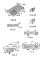
- Fig. 5 shows one embodiment of an anchoring matrix comprising a honeycomb structure bonded to a metal substrate and supporting a ceramic layer which is confined within the cellular structure or zone of the matrix;
- Fig. 5A and 5B are fragments of the cell walls of the honeycomb structure or matrix of Fig. 5 illustrating a preferred embodiment in which wall perforations (rectangular or circular openings) are employed to provide means for effecting the mechanical bonding of the ceramic layer to the anchoring matrix comprising said honeycomb structure;
- Fig. 6 is a longitudinal cross section of the anchoring matrix of Fig. 5 taken along line 6-6;
- Fig. 7 depicts an additional embodiment of the reinforced composite structure of the invention in which randomly oriented metal fibers in the form of a unitary structure (e .g., sintered metal fibers) are used to provide support for the ceramic layer, the fibers in the form of a mat, which mat is embedded in and therefore mechanically bonded to the ceramic;
- randomly oriented metal fibers in the form of a unitary structure e .g., sintered metal fibers
- Fig. 8 is a cross section of a reinforced composite structure of the invention showing the ceramic layer extending beyond the surface of the anchoring matrix;
- Fig. 9 shows schematically a die arrangement for pressing a ceramic mixture into the open structure of a metal anchoring matrix.
- the ceramic composition may comprise a variety of specific combinations of high temperature refractory materials.
- the materials may include: zirconium dioxide, ZrO2; aluminum oxide, Al2O3; magnesium oxide, MgO; calcium oxide, CaO; yttrium oxide, Y2O3; hafnium dioxide, HfO2; chromium oxide, Cr2O3; silicon dioxide, SiO2; thorium dioxide, ThO2; silicon carbide, SiC; and cerium dioxide, CeO2.
- An example of a formulation that uses several of the above materials is as follows:
- the zirconium dioxide is stabilized primarily in its cubic crystalline form by the addition of 16.9% by weight yttrium oxide.
- the yttrium oxide is in solid solution with the zirconium dioxide.
- Other minor constituents as listed above may be present.
- the zirconium dioxide may be stabilized by other additives, such as CaO, MgO, etc.
- stabilizers may range in amounts from about 3% to 25% by weight of the zirconium dioxide-stabilizer mixture.
- compositions containing substantial amounts of zirconium dioxide it is preferred that at least about 40% by weight of zirconium dioxide be present in the composition.
- chemical binders such as phosphoric acid, aluminum phosphate and other phosphate-containing chemicals are preferably included.
- Water, phenolic resin, epoxy resins and other polymers, such as synthetic or natural viscosifiers, are included as required to yield the proper consistency and porosity.
- synthetic viscosifiers are ethyl cellulose, methyl cellulose and carboxymethyl cellulose.
- Natural viscosifiers include guar gum and derivatives thereof. Guar gum has 5 to 8 times the thickening power of starch. The proper consistency of the ceramic mix is determined by the ceramic-forming technique used. The level of porosity influences the mechanical and thermal properties of the final ceramic product.
- the ceramic body may have a porosity ranging from about 10-90% by volume, preferably between about 25-50% for turbine seal applications.
- the desired porosity can be obtained by blending together coarse and fine particles at various ratios or by adding pore formers, e.g., decomposable organic materials.
- the oxide ceramics can be used in the form of agglomerates of specific size.
- the agglomerates are pre-reacted and sintered ceramic powders with or without binders.
- the sintered powders are crushed and sized utilizing conventional ceramic processing techniques.
- the porosity of the agglomerates can also be controlled to provide means of controlling the overall porosity of the ceramic product.
- the second part of the ceramic-metal composite is the metallic component.
- the metallic component is made of an alloy, preferably malleable, that generally contains combinations of some of the following elements: nickel, cobalt, iron, chromium, manganese, aluminum, titanium, zirconium, tungsten, molybdenum, hafnium, carbon, silicon and boron in the form of nickel-base, nickel-cobalt-base, cobalt-base, and iron-base alloys. Examples of such heat resistant alloys are given as follows:
- the metallic portion of the composite is used as the anchoring system. It may be attached to the metallic substrate being protected in a variety of ways, for example, by brazing, welding, diffusion bonding or incorporated as an integral part of the substrate.
- the objective is to achieve strong mechanical bonding between the ceramic anchoring system and the ceramic itself.
- the mechanical bonding should be primarily perpendicular to the surface being protected.
- a number of anchoring configurations can be used including: cellular structures, such as honeycomb structures, egg crate structures, and the like, with or without side wall treatment, for example, side wall treatment in which the walls are crimped, kinked or perforated by holes punched in the side walls.
- Wire mesh preferably oriented perpendicular to the surface being protected may be employed, as well as such reinforcing elements as wire studs, tangs, randomly oriented metallic fibers and other types of reinforcing elements cooperably and spatially arranged on the substrate in the form of a ceramic-supporting matrix.
- the metallic anchoring matrix have a substantially unitary structure, such as cellular structures, interconnecting randomly oriented metal fibers, and an intermingled arrangement of wire coils of wire mesh.
- the anchoring system or matrix is either metallurgically bonded to the substrate by brazing, welding or diffusion bonding or it is produced by casting as an integral part of the substrate. If brazed, a suitable braze composition should be used at proper brazing temperatures.
- a typical nickel-base alloy braze is one designated as AMS 4779.
- the nominal composition by weight of AMS 4779 braze is: 94.5% nickel, 2.0% boron and 3.5% silicon.
- a suitable brazing temperature would be about 2130°F (1165°C).
- a lower brazing temperature may also be employed, depending upon the braze alloy selected.
- the time at temperature is very short, e.g., typically less than about 10 minutes.
- the ceramic may be combined with the anchoring system or matrix by several readily used ceramic-forming techniques.
- Such techniques may comprise dry powder pressing, casting or ramming.
- Dry powder pressing uses pressure to form dry or nearly dry ceramic powders and binders into desired shapes and sizes.
- the powder mixture is slightly damp and tends to stick together when squeezed in the palm of one's hand.
- the amount of pressure needed can vary over an extremely wide range depending on the amount of water present or the kind and amount of binders used.
- Slip-casting using liquids to form a slurry with the ceramic powders and binders so they can be poured or otherwise formed to shape, may be employed.
- Ramming generally requires enough liquid to make the ceramic powders and binders plastically formable using low pressure, including pressure applied by hand such as with the use of a spatula. If dry powder pressing is employed, suitable dies and rams are necessary. Forms may also be made for casting and ramming; however, under certain conditions and in accordance with the anchoring matrix employed, no forms need be used when producing the ceramic layer by casting or ramming.
- the ramming technique, using a plastically formable ceramic mix, is particularly suited for attaching the ceramic-metal composite to a full-circle cylindrical configuration, such as a turbine shroud.
- the heat treatment required to yield the final ceramic bond consists first of driving out the moisture that may be present. This can be achieved by drying the ceramic composition at temperatures from room temperature to about 200°F (93°C), with the time at temperature being as little as four hours, although shorter times can be employed. While the ceramic bond is generally produced by heat treatment at temperatures below about 2000°F (1095°C), it is preferred, depending on the chemical bonding agent used, to employ a heat treatment at temperatures ranging up to about 1300°F (705°C), e.g. about 500°F (260°C) to 1300°F (705°C) preferably for at least about six hours at the preselected temperature. To take full advantage of the bond forming characteristics, 700°F (371°C) to 1100°F (593°C) is the preferred heat treatment temperature range when using phosphate-bonding agents.
- Fig. 1 depicts a section in three dimensions of a ceramic-metal composite comprising a ceramic layer 10 mechanically bonded to a metal substrate 11, e.g., a portion of a turbine shroud, via a metallic anchoring matrix comprising a plurality of spatially and cooperably arranged reinforcing elements in the form of a substantially uniform array of studs 12 bonded to or integral with substrate 11.
- the studs may have various shapes as shown in Fig. 1A (plain or nail head) and Fig. 1B in which the stud has an enlarged mid-section for further mechanically bonding or coupling the ceramic layer 10 to the supporting matrix.
- the studs are arranged sufficiently close to each other, preferably in staggered rows, to assure the interruption of or to minimize the formation of horizontal strains that may occur during thermal shock.
- the mechanical coupling is primarily substantially perpendicular to the surface of the substrate. If there is a wide disparity in thermal expansion between the ceramic layer and the substrate, shear strains are developed horizontal to the substrate surface. Also, tensile strains arise in the direction perpendicular to the substrate surface. In both cases, these strains can lead to cracking parallel to the substrate surface. In the absence of additional bonding or anchoring forces perpendicular to the substrate surface, the ceramic layer tends to peel off of or spall from the surface.
- Fig. 2 shows a ceramic-metal composite comprising a ceramic layer 10A mechanically bonded to a metal substrate 11A via a metallic anchoring matrix 12A comprising a wire mesh strip in which the reinforcing elements are a plurality of interwoven wires.
- the strip is disposed on edge transverse to the surface of the substrate, for example, substantially perpendicular thereto, with the strip side winding sinuously across the surface of the substrate as shown.
- a strong mechanical bond is achieved between the ceramic 10A and the anchoring matrix by virtue of the penetration of the ceramic into and through the interstices of the woven wire strip.
- the strip is metallurgically bonded to the metal substrate.
- wire mesh tabs 12B are used as the reinforcing elements for mechanically bonding ceramic layer 10B to substrate 11B.
- the wire mesh tabs are L-shaped with the legs thereof metallurgically bonded to substrate 11B to provide the anchoring matrix. It is preferred that the tabs be staggered as shown in the figure which also depicts tab 12B in Fig. 3A having two legs (inverted "T"). The tabs are embedded in ceramic layer 10B.
- the ceramic-metal composite of Fig. 4 depicts the use of wire coils 12C arranged side-by-side on and metallurgically bonded (e.g. brazed) to substrate 11C, the coils being peripherally intermingled as shown to provide in effect a unitary anchoring matrix embedded in ceramic layer 106 strongly mechanically bonded to substrate 11C.
- Fig. 5 is a preferred embodiment of a ceramic-metal composite in which the metallic anchoring matrix attached to substrate 11D is a honeycomb structure.
- the plurality of reinforcing elements are hexagonal cells 12D into which is confined ceramic layer 10D.
- a section of the composite is shown with the ceramic omitted to more clearly show the cellular structure of the matrix, including the side walls.
- the side walls of the cells are preferably perforated with a hole as shown in Fig. 5A or a slot as shown in Fig. 5B to provide improved mechanical bonding of the ceramic with the unitary structure of the honeycomb.
- Fig. 6 is a cross-section of Fig. 5 taken along line 6-6 as shown.
- the ceramic-metal composite of Fig. 7 illustrates the use of a metal mat or pad of randomly oriented metal fibers 12E as a unitary structure attached to substrate 11E by, for example, brazing, the ceramic layer 10E permeating the interstices of the mat substantially completely to provide a strong mechanical bond thereof to the substrate.
- Fig. 8 is a cross-section of a ceramic-metal composite comprising a metal substrate 13 of a high temperature alloy to which is metallurgically bonded, e.g., brazed or welded, an anchoring matrix 14 having an egg crate structure with angularly deformed side walls 14A filled with a chemically bonded ceramic plus an excess to provide an outer layer 15 as shown.
- the deformed side walls assure strong mechanical bonding of the ceramic layer to the substrate.
- one method of filing the open spaces of the anchoring matrix with a ceramic composition is by pressing using a die arrangement as shown in Fig. 9.
- An open rectangular die ring 16 is snugly fitted around metal substrate 18 to which is attached anchoring matrix 19 by brazing or welding.
- the reinforcing elements 19A (side walls) of the matrix are deformed, e.g., crinkled, to assure mechanical bonding of the ceramic to matrix 19.
- the side walls may be crinkled during pressing, if desired.
- the open spaces of the anchoring matrix are filled with a ceramic composition 20.
- a die block 17 is placed into the rectangular die ring as shown and a pressure P applied to force the ceramic substantially completely into the open spaces of the matrix. The view shown is before completion of the pressing.
- the invention offers the following advantages.
- Low temperature can be used to form the ceramic bond; hence, heat damage to engine parts is avoided.
- Several different ceramic fabrication techniques are readily available and adaptable, the techniques including pressing, casting and ramming.
- the thickness of the seal can be readily varied up to 2.5cm (1 inch) or greater. A thickness of as little as about 0.75mm (thirty thousandths of an inch) can be produced.
- microstructure and properties can be custom tailored to different requirements, thus providing control over abradability, erosion resistance and hardness.
- the long term thermal stability is greater in the ceramic-metal composite compared to metal per se .
- Ceramic components are not subject to degradation through oxidation as generally occurs with metal coatings.
- a cellular structure in the form of a honeycomb with overall dimensions of 6.3 x 23.8 x 74.6mm (1/4 x 15/16 x 2-15/16 inches) and with 6.3mm (1/4 inch) hexagonal cells and 0.05mm (0.002 inch) wall thickness was brazed to a 3.1 x 27.5 x 79.3mm (1/8 x 1-1/8 x 3-1/8 inch) nickel alloy substrate.
- the honeycomb was made from Hastelloy X having a composition by weight of about 22% chromium, about 18.5% iron, about 9% molybdenum, about 1.5% cobalt, about 0.6% tungsten, about 0.5% manganese, about 0.5% silicon, about 0.1% carbon and the balance essentially nickel.
- a braze alloy identified as Amdry 788 (Alloy Metals, Inc.) was employed having a composition by weight of about 22% chromium, about 21% nickel, about 14% tungsten, about 2% boron, about 2% silicon, about 0.03% lanthanum and the balance cobalt.
- An acrylic adhesive was sprayed on one 27.5 x 79.3mm (1-1/8 x 3-1/8 inch) surface of the substrate.
- the braze powder was then sprinkled on the tacky adhesive surface.
- the honeycomb was centered on the surface and the assembly was heated under vacuum to 2300°F (1260°C). The sample was held at that temperature for only three minutes and then cooled to room temperature.
- a ceramic batch formulation was prepared having the following composition by weight. Four percent by weight of calcium oxide was used to stabilize the zirconium dioxide. The dry powders were mixed by tumbling in a jar mill; after which, the phosphoric acid was added and mixed with the oxide constituents by hand.
- the phosphoric acid used in all of the examples was 85% concentrated.
- a rectangular die designed to make 6.3 x 25.4 x 76.2mm (1/4 x 1 x 3 inch) wafers was placed on top of the honeycomb substrate assembly.
- the die walls surrounded the honeycomb and rested on top of the substrate.
- the die cavity was charged with the ceramic formulation and the ceramic was pressed into the honeycomb cells under a pressure of 69 MPa (10,000 pounds per square inch) using a die block fitted into the rectangular die.
- the resulting piece was dried at 176°F (80°C) for six hours and then heat treated at 700°F (371°C) for four hours.
- the test piece was then exposed to more than 1000 thermal shock cycles.
- the thermal shock test entailed cycling the ceramic side of the sample between approximately 1100°F (593°C) to 2300°F (1260°C).
- the metal substrate side of the sample was cycled between 750°F (400°C) to 1225°F (663°C).
- a hydrogen-oxygen torch was used to heat the ceramic side and a propane-oxygen torch was used on the substrate side. Approximately ten seconds were required to heat both sides to their respective upper temperatures.
- the sample was maintained at the high temperatures for one minute and then cooled for one minute by blowing air on the substrate side. Upon reaching 750°F (400°C) on the substrate side, the cycle was repeated.
- honeycomb 25.4 x 33mm (1 x 1.3 inches), with 3.1mm (1/8 inch) hexagonal cells 0.05mm (0.002 inch) wall thickness and 2mm (0.080 inch) height were brazed to vane sections used in a first stage turbine of a gas turbine engine.
- the honeycomb composition was the same as that described in Example 1.
- the braze alloy employed was that designated as AMS 4777 having a composition by weight of about 7% Cr, about 3.2% B, about 4.5% Si, about 3% Fe and the balance essentially nickel.
- the brazing procedure employed was the same as that described in Example 1 except that the brazing temperature was 1960°F (1070°C).
- slots of about 0.5mm (0.020 inch) wide by about 6.3mm (0.025 inch) high were cut into the walls on the side of the honeycomb to be brazed to the vane sections.
- a ceramic oxide formulation having the following composition by weight was made: The zirconium dioxide was stabilized with 16.9% yttrium oxide. All mixing was done as described in Example 1.
- the agglomerate used in the composition given was made from 5 ⁇ m yttrium oxide stabilized zirconium dioxide powder.
- a preblend of 18.9% by weight glycerin, 13.9% by weight colloidal silica, 1.7% by weight of a viscosifier (referred to by the designation Jaguar Polymer 315 which is a guar derivative) and 65.5% by weight water was mixed in a blender.
- the zirconium dioxide powder was then added until the total mixture consisted of approximately 17% preblend and 83% zirconium dioxide.
- the material was then extruded in the shape of 6.3mm (1/4 inch) diameter "noodles.” These "noodles" were air dried, calcined at 2012°F (1100°C) and sintered at 3000°F (1650°C). The resulting hard-fired product contained between 30-40% porosity by volume. The product was ground in a roll crusher, screened to the U.S. sieve sizes given above and acid leached in a mixture of nitric acid and hydrochloric acid to remove iron picked up from the crushing operation.
- the ceramic oxide mixture was pressed into the honeycomb cells at a pressure of 45 MPa (6500 psi) using a die as in Example 1. After drying 16 hours at 176°F (80°C) and heat treating at 700°F (371°C) for four hours, the ceramic surfaces of the pieces were ground so that the total height of the ceramic-honeycomb composite was between 1.25 and 1.52mm (0.050 and 0.060 inches). The honeycomb cell edges were exposed on the ground surface of the ceramic.
- the slots in the honeycomb walls discussed earlier allowed the ceramic to extrude from one cell to another affording mechanical grab.
- the ceramic itself may be viewed as a series of pieces having small cross section perpendicular to the direction of heat travel. This small cross section limits the magnitude of thermal strains that arise and generally enhances thermal shock resistance.
- honeycomb 23.8 x 74.6mm (15/16 x 2-15/16 inches), with 3.1mm (1/8 inch) hexagonal cells, 0.05mm (0.002 inch) wall thickness and 2mm (0.080 inch) height was brazed to a nickel alloy substrate.
- the honeycomb composition was made of Hastelloy X as described in Example 1. The same brazing procedure was used, except that the alloy was AMS 4779 comprising by weight about 94.5% Ni, about 2% B and 3.5% Si, the brazing temperature employed being about 2130°F (1165°C).
- a ceramic oxide batch formulation was produced having the following composition by weight: After the dry constituents were blended in a jar mill, phosphoric acid and water were added and blended in by hand using a spatula. After mixing, the material had a paste-like consistency.
- the mix was rammed into honeycomb using a spatula because of the plasticity of the mix.
- the sample was dried at 176°F (80°C) for 16 hours and heat treated at 700°F (371°C) for 16 hours.
- the surface of the ceramic was ground down so that the honeycomb anchor was exposed.
- the thickness of the ceramic-metal composite was 1.8mm (0.070 inches).
- the sample was exposed to 650 thermal shock cycles as described in Example 1. After completion of the cycles, the sample was exposed to constant heating on the ceramic side for a cumulative 78 hours. During this latter treatment, the temperature on the ceramic side was between 2100°F (1150°C) to 2350°F (1288°C) while the unheated substrate side equilibrated at 1100°F (593°C). After this treatment, the sample was examined and found to have suffered negligible damage.
- Coils of 0.25mm (0.010 inch) diameter nickel-chrome wire were formed on a mandrel.
- the coils were approximately 6.3mm (1/4 inch) in diameter and approximately 76mm (3 inches) long.
- Five such coils were brazed lengthwise and side-by-side to 3.1 x 28.5 x 79.3mm (1/8 x 1-1/8 x 3-1/8 inch) nickel alloy substrate, the coils being peripherally intermingled or overlapped with respect to each other substantially across the width of the substrate.
- the braze composition and procedure employed were essentially the same as in Example 3.
- a form or die was placed around the coils so that a ceramic mixture having dimensions 6.3 x 25.4 x 76.2mm (1/4 x 1 x 3 inch) could be rammed in place on top of, into and around the coils.
- the ceramic composition was the same as that given in Example 3, including the drying and heat treatment.
- a ceramic oxide composition was applied to a curved substrate having a recessed land and having integrally cast studs or posts for anchoring.
- the land was 37.6 x 108mm (1-1/2 x 4-1/4 inches) and was recessed to 3.1mm (1/8 inch) in depth.
- the posts or studs were approximately 0.8 x 2.4mm (1/32 x 3/32 inches) x 3.1mm (1/8 inch) high and were spaced approximately 4.8 to 6.3mm (3/16 to 1/4 inch) apart.
- the radius of curvature of the substrate was approximately 35.6cm (14 inches).
- the ceramic oxide formulation had the following composition by weight: As will be noted, the ceramic oxide composition comprises essentially aluminum oxide.
- a block of wood was cut such that one face was concave with the same radius as the outer radius of the substrate.
- a second block of wood was cut such that one face was convex with the same radius as the inner radius of the substrate.
- the ceramic composition which was slightly damp was spread evenly into the recess of the substrate until it filled the recess and was approximately 4.7mm (3/16 inch) above the top. This material was then pressed into the recess at 17.25 MPa (2500 psi) using the wood rams as described above. The sample was dried and heat treated as described in Example 1.
- the sample was subject to 90 thermal shock cycles as described in Example 1. Following the thermal shock treatment, the sample was examined under a stereo microscope and found to have suffered no detectable thermal shock damage.
- a ceramic formulation having the following composition by weight was made: The formulation was mixed as described in Example 1. Ceramic wafers, 4.7 x 25.4 x 76.2mm (3/16 x 1 x 3 inches), were pressed at a pressure of 10,000 psi. These wafers were dried at 176°F (80°C) and heat treated at 700°F (371°C) as described in Example 1.
- the physical properties of the wafers were as follows: Test procedures for determining the physical properties are well known to those skilled in the art. The three point bend strength was determined over a 50.8mm (2 inch) span, the wafers being freely supported on two knife edge supports about 25.4mm (1 inch) across and 50.8mm (2 inches) apart with the load applied at the center of the span.
- This example shows that phosphate-containing compounds, other than phosphoric acid, can be used to form a low temperature bond.
- a ceramic formulation having the following composition by weight was made:
- This composition was mixed as described in Example 3, the material having a paste-like consistency after mixing.
- the material was rammed into a rectangular steel mold designed to form 3.1 x 25.4 x 76.2mm (1/8 x 1 x 3 inch) wafers. A spatula was used to ram the samples.
- the wafers were dried at 176°F (80°C) for 16 hours and heat treated at 700°F (371°C) for 16 hours. After this heat treatment, the low temperature formed ceramic bond was present, despite the lower level of phosphoric acid used (4.8% as compared to 9.5 and 10.0% for other formulations described in previous examples).
- colloidal silica The purpose of the colloidal silica is to form a second bond at elevated temperatures.
- Coils of 0.25mm (0.010 inch) diameter nickel-chrome alloy wire (80% Ni-20% Cr) were formed on a mandrel and brazed to a 3.1 x 27.5 x 79.3mm (1/8 x 1-1/8 x 3-1/8 inch) nickel-alloy substrate as described in Example 4.
- a ceramic formulation having the following composition by weight was made:
- a die designed to make 25.4 x 76.2mm (1 x 3 inch) wafers having thicknesses of up to one inch was placed on top of the coil-substrate assembly.
- the die walls surrounded the coils and rested on top of the substrate.
- the die cavity was charged with the ceramic formulation. Care was taken to assure that the material was placed into and around the coils.
- the ceramic material was then pressed to 19 x 25.4 x 76.2mm (3/4 x 1 x 3 inch) shape under a pressure of 69 MPa (10,000 psi).
- the sample was dried at 176°F (80°C) for 16 hours and heat treated at 700°F (371°C) for 16 hours.
- a ceramic formulation of the following composition by weight was made: Mixing of the above sample was as described in Example 1. Ceramic wafers 4.7 x 25.4 x 76.2mm (3/16 x 1 x 3 inches) were pressed at a pressure of 10,000 psi. These wafers were dried at 176°F (80°C) for 16 hours and heat treated at 700°F (371°C) for 16 hours.
Landscapes
- Engineering & Computer Science (AREA)
- Mechanical Engineering (AREA)
- General Engineering & Computer Science (AREA)
- Ceramic Engineering (AREA)
- Ceramic Products (AREA)
- Laminated Bodies (AREA)
Claims (18)
- Structure composite renforcée
comprenant une couche résistante à la chaleur et liée par voie chimique d'une composition à base de céramique (10, 15, 20) fixée par voie mécanique à un substrat métallique (11, 13, 18),cette structure comprenant une matrice d'ancrage métallique caractérisée par plusieurs éléments de renforcement (12, 14, 19) répartis de manière à coopérer, choisis parmi des structures alvéolaires, une structure unitaire de fibres métalliques orientées de manière aléatoire, un ensemble d'enroulements de fils métalliques disposés côte à côte et entremêlés à leur périphérie, des picots et/ou des languettes à peu près uniformément répartis, et un treillis métallique, l'ensemble coopérant des éléments de renforcement étant tel par rapport au substrat, que les forces de liaison mécanique ou d'ancrage, s'étendent principalement dans une direction à peu près perpendiculaire à la surface du substrat, de sorte que la rupture de la couche de céramique renforcée sous l'effet de contraintes de cisaillement parallèles à la surface du substrat, et sous l'effet de contraintes de tension perpendiculaires à la surface, est à peu près empêchée,cette matrice étant à peu près uniformément fixée sur la surface du substrat, et s'étendant à partir de cette surface, les éléments de renforcement répartis de cette matrice délimitant ensemble une zone occupable par la céramique d'une épaisseur déterminée, au voisinage de la surface du substrat et en s'adaptant à la forme de celle-ci,ladite composition à base de céramique résistante à la chaleur et liée par voie chimique étant au moins confinée dans cette zone en contact intime et liée par voie mécanique avec les éléments de renforcement,la composition à base de céramique liée par voie chimique étant poreuse avec un volume de pores de 10 % à 90 %, et étant préparée en mélangeant un agent de liaison chimique à basse température choisi parmi l'acide phosphorique, le phosphate d'aluminium, l'acide chromique, le silicate de sodium, la silice colloïdale et un gel de silice, avec ladite composition à base de céramique, et en chauffant cette composition venue de mélange à une basse température en dessous de la température de frittage normale de la céramique lorsque l'agent de liaison chimique à basse température n'est pas présent, cette température de liaison chimique étant inférieure à environ 1 095 °C,de sorte que ladite composition à base de céramique résistante à la chaleur est renforcée, et est fortement liée par voie mécanique sous la forme d'une couche sur le substrat, grâce à la matrice métallique fixée au substrat, en étant simultanément usable par abrasion. - Structure composite renforcée selon la revendication 1, dans laquelle la matrice métallique est fixée sur le substrat à l'aide d'une liaison métallurgique formée par brasage, soudage ou liaison par diffusion.
- Structure composite renforcée selon la revendication 1 ou 2, dans laquelle la composition à base de céramique liée par voie chimique, est choisie parmi ZrO₂, Al₂O₃, MgO, CaO, Y₂O₃, HfO₂, Cr₂O₃, SiO₂, ThO₂, CeO₂ et SiC ainsi que les mélanges d'au moins deux de ces composés.
- Structure composite renforcée selon la revendication 3, dans laquelle la composition à base de céramique liée par voie chimique, comprend principalement une composition liée par un phosphate.
- Structure composite renforcée selon la revendication 4, dans laquelle la composition à base de céramique comprend principalement une composition à base de bioxyde de zirconium (ZrO₂) stabilisé, liée par un phosphate, et dans laquelle le volume des pores, varie d'environ 25 % à 50 %.
- Structure composite renforcée selon la revendication 3, dans laquelle la matrice d'ancrage métallique est une structure alvéolaire, au moins la zone délimitée par cette structure étant remplie avec une composition à base de céramique liée par voie chimique, comprenant principalement du bioxyde de zirconium (ZrO₂) stabilisé, lié avec un phosphate.
- Structure composite renforcée selon l'une quelconque des revendications précédentes, dans laquelle les parois constituant la structure alvéolaire, sont dotées de moyens pour faciliter la liaison mécanique de la composition à base de céramique, sur la structure alvéolaire.
- Structure composite renforcée selon l'une quelconque des revendications précédentes, dans laquelle la matrice métallique d'ancrage, consiste en alliage résistant à la chaleur choisi parmi les alliages à base de nickel, à base de nickel et de cobalt, à base de cobalt, et à base de fer.
- Joint usable par abrasion résistant à la chaleur destiné à être employé à des températures élevées, ce joint étant formé par la structure composite renforcée selon l'une quelconque des revendications 1 à 8.
- Procédé de fabrication d'une structure composite renforcée, comprenant une couche résistante à la chaleur d'une composition de céramique liée par voie chimique, fixée par voie mécanique à un substrat métallique, selon lequel :on munit un substrat métallique d'une matrice métallique d'ancrage caractérisée par plusieurs éléments de renforcement répartis de manière à coopérer, choisis parmi les structures alvéolaires, une structure unitaire de fibres métalliques orientées de manière aléatoire, un ensemble d'enroulements de fils métalliques disposés côte à côte et entremêlés à leur périphérie, des picots et/ou des languettes à peu près uniformément répartis, et un treillis métallique, l'ensemble coopérant des éléments de renforcement étant tel par rapport au substrat, que les forces de liaison mécaniques ou d'ancrage, s'étendent principalement dans une direction à peu près perpendiculaire à la surface du substrat, de sorte que la rupture de la couche de céramique renforcée sous l'effet de contraintes de cisaillement parallèles au substrat, et sous l'effet de contraintes de tension perpendiculaires au substrat, est à peu près empêchée,cette matrice étant à peu près uniformément fixée sur le substrat, et s'étendant à partir de sa surface, les éléments de renforcement de la matrice délimitant ensemble une zone occupable par la céramique d'une épaisseur déterminée, au voisinage du substrat en s'adaptant à la forme de sa surface,on confine au moins dans cette zone, en contact intime avec les éléments de renforcement, une composition de céramique contenant un agent de liaison à basse température, choisi parmi l'acide phosphorique, le phosphate d'aluminium, l'acide chromique, le silicate de sodium, la silice colloïdale et un gel de silice, et on chauffe ladite composition à base de céramique confinée susceptible d'être liée par voie chimique, à une température inférieure à la température de frittage normale de la céramique lorsque l'agent de liaison chimique à basse température n'est pas présent, afin d'assurer la liaison chimique de la composition, la température de liaison chimique étant inférieure à environ 1 095 °C,de sorte que l'on obtient une couche poreuse renforcée d'une céramique résistante à la chaleur et liée par voie chimique, ayant un volume de pore de 10 % à 90 %, fortement liée par voie mécanique sur le substrat à l'aide de la matrice fixée à ce substrat.
- Procédé selon la revendication 10, dans lequel la température de liaison chimique n'est pas supérieure à 705 °C.
- Procédé selon la revendication 10 ou 11, dans lequel la matrice métallique est fixée sur le substrat par l'intermédiaire d'une liaison métallurgique produite par brasage, soudage ou liaison par diffusion.
- Procédé selon l'une quelconque des revendications 10 à 12, dans lequel la composition à base de céramique liée par voie chimique, est choisie parmi ZrO₂, Al₂O₃, MgO, CaO, Y₂O₃, HfO₂, Cr₂O₃, SiO₂, ThO₂, CeO₂ et SiC, ainsi que les mélanges d'au moins deux de ces composés.
- Procédé selon la revendication 13, dans lequel la composition à base de céramique liée par voie chimique comprend principalement une composition liée avec un phosphate.
- Procédé selon la revendication 14, dans lequel la composition à base de céramique comprend principalement une composition à base de bioxyde de zirconium (ZrO₂) stabilisé, lié avec un phosphate, et dans lequel le volume des pores varie d'environ 25 % à 50 %.
- Procédé selon l'une quelconque des revendications 10 à 15, la matrice d'ancrage métallique consistant en une structure alvéolaire, la zone délimitée par la structure étant remplie avec la composition à base de céramique liée par voie chimique comprenant principalement du bioxyde de zirconium (ZrO₂) stabilisé et lié avec un phosphate.
- Procédé selon la revendication 16, dans lequel les parois constituant la structure alvéolaire, sont dotées de moyens pour faciliter la liaison mécanique de la composition à base de céramique à ladite structure alvéolaire.
- Procédé selon l'une quelconque des revendications 10 à 17, dans lequel la matrice d'ancrage métallique consiste en un alliage résistant à la chaleur choisi parmi les alliages à base de nickel, à base de nickel et de cobalt, à base de cobalt et à base de fer.
Applications Claiming Priority (2)
| Application Number | Priority Date | Filing Date | Title |
|---|---|---|---|
| US06/701,022 US4639388A (en) | 1985-02-12 | 1985-02-12 | Ceramic-metal composites |
| US701022 | 1985-02-12 |
Publications (3)
| Publication Number | Publication Date |
|---|---|
| EP0192162A2 EP0192162A2 (fr) | 1986-08-27 |
| EP0192162A3 EP0192162A3 (en) | 1987-06-24 |
| EP0192162B1 true EP0192162B1 (fr) | 1991-04-10 |
Family
ID=24815754
Family Applications (1)
| Application Number | Title | Priority Date | Filing Date |
|---|---|---|---|
| EP86101695A Expired - Lifetime EP0192162B1 (fr) | 1985-02-12 | 1986-02-11 | Composites céramique-métal |
Country Status (6)
| Country | Link |
|---|---|
| US (1) | US4639388A (fr) |
| EP (1) | EP0192162B1 (fr) |
| JP (1) | JPH072394B2 (fr) |
| CA (1) | CA1265913A (fr) |
| DE (1) | DE3678591D1 (fr) |
| IL (1) | IL77858A (fr) |
Cited By (1)
| Publication number | Priority date | Publication date | Assignee | Title |
|---|---|---|---|---|
| KR101510487B1 (ko) * | 2007-05-22 | 2015-04-08 | 코닝 인코포레이티드 | 내화성 세라믹과 금속의 결합방법 및 그 응용 |
Families Citing this family (127)
| Publication number | Priority date | Publication date | Assignee | Title |
|---|---|---|---|---|
| JPS6399867A (ja) * | 1986-10-17 | 1988-05-02 | ペルメレツク電極株式会社 | リン酸カルシウム化合物被覆複合材及びその製造方法 |
| JPS63231928A (ja) * | 1987-03-20 | 1988-09-28 | 日本碍子株式会社 | セラミックス・金属結合体 |
| US4803108A (en) * | 1987-05-01 | 1989-02-07 | Essex Specialty Products, Inc. | Honeycomb reinforcing sheet for the reinforcement of panels and method of reinforcing panels |
| US4867639A (en) * | 1987-09-22 | 1989-09-19 | Allied-Signal Inc. | Abradable shroud coating |
| US4828926A (en) * | 1987-12-04 | 1989-05-09 | Inotel Inc. | Aluminum phosphate bonded micas and composite thereof |
| GB2239214B (en) * | 1989-12-23 | 1993-11-03 | Rolls Royce Plc | A sandwich structure and a method of manufacturing a sandwich structure |
| KR940002027B1 (ko) * | 1990-11-15 | 1994-03-14 | 신꼬 판텍 가부시끼가이샤 | 졸겔법에 의한 글래스 라이닝 기기의 라이닝 글래스층의 보수 방법 |
| DE4231338A1 (de) * | 1992-09-18 | 1994-03-24 | Emitec Emissionstechnologie | Verfahren zum Beloten einer metallischen Struktur, insbesondere von Teilbereichen eines Wabenkörpers |
| DE4238369C2 (de) * | 1992-11-13 | 1996-09-26 | Mtu Muenchen Gmbh | Bauteil aus einem metallischen Grundsubstrat mit keramischer Beschichtung |
| CA2113396A1 (fr) * | 1993-08-30 | 1995-03-01 | Etsuji Kimura | Refractaire resistant aux melanges basiques |
| US5780157A (en) * | 1994-06-06 | 1998-07-14 | Ultramet | Composite structure |
| US5618633A (en) * | 1994-07-12 | 1997-04-08 | Precision Castparts Corporation | Honeycomb casting |
| JP3813654B2 (ja) * | 1995-02-09 | 2006-08-23 | 日本碍子株式会社 | セラミックスの接合構造およびその製造方法 |
| US5786031A (en) * | 1995-06-07 | 1998-07-28 | Engelhard Corporation | Barrier for a metal substrate |
| GB9513252D0 (en) * | 1995-06-29 | 1995-09-06 | Rolls Royce Plc | An abradable composition |
| US5890268A (en) * | 1995-09-07 | 1999-04-06 | Case Western Reserve University | Method of forming closed cell metal composites |
| US6102656A (en) * | 1995-09-26 | 2000-08-15 | United Technologies Corporation | Segmented abradable ceramic coating |
| JPH1088368A (ja) * | 1996-09-19 | 1998-04-07 | Toshiba Corp | 遮熱コーティング部材およびその作製方法 |
| US5976695A (en) * | 1996-10-02 | 1999-11-02 | Westaim Technologies, Inc. | Thermally sprayable powder materials having an alloyed metal phase and a solid lubricant ceramic phase and abradable seal assemblies manufactured therefrom |
| EP0935009B1 (fr) * | 1998-02-05 | 2002-04-10 | Sulzer Markets and Technology AG | Corps moulé revêtu d'une couche |
| US7563504B2 (en) * | 1998-03-27 | 2009-07-21 | Siemens Energy, Inc. | Utilization of discontinuous fibers for improving properties of high temperature insulation of ceramic matrix composites |
| US6977060B1 (en) | 2000-03-28 | 2005-12-20 | Siemens Westinghouse Power Corporation | Method for making a high temperature erosion resistant coating and material containing compacted hollow geometric shapes |
| US6641907B1 (en) | 1999-12-20 | 2003-11-04 | Siemens Westinghouse Power Corporation | High temperature erosion resistant coating and material containing compacted hollow geometric shapes |
| US6197424B1 (en) | 1998-03-27 | 2001-03-06 | Siemens Westinghouse Power Corporation | Use of high temperature insulation for ceramic matrix composites in gas turbines |
| US6013592A (en) * | 1998-03-27 | 2000-01-11 | Siemens Westinghouse Power Corporation | High temperature insulation for ceramic matrix composites |
| US6733907B2 (en) | 1998-03-27 | 2004-05-11 | Siemens Westinghouse Power Corporation | Hybrid ceramic material composed of insulating and structural ceramic layers |
| US6676783B1 (en) | 1998-03-27 | 2004-01-13 | Siemens Westinghouse Power Corporation | High temperature insulation for ceramic matrix composites |
| US6291806B1 (en) * | 1998-10-01 | 2001-09-18 | Usf Filtration And Separations Group, Inc. | Process for bonding workpieces |
| US6235370B1 (en) | 1999-03-03 | 2001-05-22 | Siemens Westinghouse Power Corporation | High temperature erosion resistant, abradable thermal barrier composite coating |
| US6355356B1 (en) * | 1999-11-23 | 2002-03-12 | General Electric Company | Coating system for providing environmental protection to a metal substrate, and related processes |
| AU2001265141A1 (en) * | 2000-05-26 | 2001-12-11 | University Of Virginia Patent Foundation | Multifunctional periodic cellular solids and the method of making thereof |
| ATE430909T1 (de) * | 2000-07-14 | 2009-05-15 | Univ Virginia | Schaum für wärmetauscher |
| US6577018B1 (en) * | 2000-08-25 | 2003-06-10 | Micron Technology, Inc. | Integrated circuit device having reduced bow and method for making same |
| DE10117127B4 (de) * | 2001-04-06 | 2009-12-31 | Alstom Technology Ltd. | Verbundaufbau zwischen metallischen und nichtmetallischen Materialien |
| DE10117128A1 (de) * | 2001-04-06 | 2002-10-10 | Alstom Switzerland Ltd | Verfahren zur Herstellung von Verbundaufbauten zwischen metallischen und nichtmetallischen Materialien |
| DE10121019A1 (de) * | 2001-04-28 | 2002-10-31 | Alstom Switzerland Ltd | Gasturbinendichtung |
| US6846574B2 (en) * | 2001-05-16 | 2005-01-25 | Siemens Westinghouse Power Corporation | Honeycomb structure thermal barrier coating |
| DE10124398A1 (de) * | 2001-05-18 | 2002-11-21 | Rolls Royce Deutschland | Verfahren zur Aufbringung einer keramischen Schicht auf einen metallischen Grundkörper sowie Wärmedämmungsschichtsystem mit einer keramischen Schicht auf einem metallischen Grundkörper |
| EP1275748A3 (fr) * | 2001-07-13 | 2004-01-07 | ALSTOM (Switzerland) Ltd | Revêtement resistant aux temperatures elevées avec des bosses localles enrobées et son procédé de fabrication |
| SG102637A1 (en) * | 2001-09-10 | 2004-03-26 | Micron Technology Inc | Bow control in an electronic package |
| US6884384B2 (en) | 2001-09-27 | 2005-04-26 | Siemens Westinghouse Power Corporation | Method for making a high temperature erosion resistant material containing compacted hollow geometric shapes |
| CA2358624C (fr) * | 2001-10-10 | 2009-12-22 | The Westaim Corporation | Composition atomisable |
| EP1327703A1 (fr) * | 2002-01-15 | 2003-07-16 | Siemens Aktiengesellschaft | Système de revêtement avec une couche poreuse |
| EP1531983A1 (fr) * | 2002-05-30 | 2005-05-25 | University Of Virginia Patent Foundation | Metaux cellulaires d'amortissement actifs et leur procede de fabrication et d'utilisation |
| WO2004022868A2 (fr) * | 2002-09-03 | 2004-03-18 | University Of Virginia Patent Foundation | Systemes de protection contre l'explosion et les projectiles et procede de production associe |
| WO2004022869A2 (fr) | 2002-09-03 | 2004-03-18 | University Of Virginia Patent Foundation | Procede de production de structures sandwich a ame en treillis et structures associees |
| US6858174B2 (en) * | 2002-09-03 | 2005-02-22 | Ceramatec, Inc. | Process for casting ceramic materials |
| US6884470B2 (en) | 2002-10-03 | 2005-04-26 | General Electric Company | Application method for abradable material |
| FR2846034B1 (fr) * | 2002-10-22 | 2006-06-23 | Snecma Moteurs | Carter, compresseur, turbine et turbomoteur a combustion comprenant un tel carter |
| DE10259963B4 (de) * | 2002-12-20 | 2010-04-01 | Mtu Aero Engines Gmbh | Wabendichtung |
| WO2005014216A2 (fr) * | 2003-02-14 | 2005-02-17 | University Of Virginia Patent Foundation | Procedes de fabrication de structures d'armature multifonctions et multicouches et structures associees |
| JP4402362B2 (ja) * | 2003-04-04 | 2010-01-20 | キヤノン株式会社 | 画像読取装置、その制御方法、プログラムおよび記憶媒体 |
| US20050042881A1 (en) * | 2003-05-12 | 2005-02-24 | Tokyo Electron Limited | Processing apparatus |
| WO2004110740A1 (fr) * | 2003-05-28 | 2004-12-23 | University Of Virginia Patent Foundation | Structure antichoc polyvalente a cellules rentrantes et procedes de fabrication et d'utilisation |
| DE10357180A1 (de) * | 2003-12-08 | 2005-06-30 | Alstom Technology Ltd | Verbundaufbau zwischen metallischen und nichtmetallischen Materialien |
| DE102004031255B4 (de) * | 2004-06-29 | 2014-02-13 | MTU Aero Engines AG | Einlaufbelag |
| US7481248B2 (en) * | 2004-09-15 | 2009-01-27 | Pratt & Whitney Canada Corp. | Flexible heat shields and method |
| GB0425595D0 (en) * | 2004-11-20 | 2004-12-22 | Rolls Royce Plc | A laminate material |
| US7387758B2 (en) * | 2005-02-16 | 2008-06-17 | Siemens Power Generation, Inc. | Tabbed ceramic article for improved interlaminar strength |
| US7374818B2 (en) * | 2005-05-23 | 2008-05-20 | United Technologies Corporation | Coating system for silicon based substrates |
| WO2007096986A1 (fr) * | 2006-02-24 | 2007-08-30 | Ibiden Co., Ltd. | Dispositif de chauffage de face d'extremite, procede de sechage de la face d'extremite d'un assemblage en nid d'abeille et procede de production de structures en nid d'abeille |
| DE102006009860A1 (de) * | 2006-03-03 | 2007-09-06 | Mtu Aero Engines Gmbh | Verfahren zur Herstellung eines Dichtsegments und Dichtsegment zur Verwendung in Verdichter- und Turbinenkomponenten |
| US8360361B2 (en) | 2006-05-23 | 2013-01-29 | University Of Virginia Patent Foundation | Method and apparatus for jet blast deflection |
| EP1890010B1 (fr) * | 2006-08-10 | 2016-05-04 | United Technologies Corporation | Ensemble de virole de turbine en céramique |
| US7775772B2 (en) | 2006-11-08 | 2010-08-17 | General Electric Company | System for manufacturing a rotor having an MMC ring component and an airfoil component having MMC airfoils |
| US20080274336A1 (en) * | 2006-12-01 | 2008-11-06 | Siemens Power Generation, Inc. | High temperature insulation with enhanced abradability |
| US8186566B2 (en) * | 2007-03-10 | 2012-05-29 | Nexgeneering Technology Llc | Method for cohesively bonding metal to a non-metallic substrate |
| US7819625B2 (en) * | 2007-05-07 | 2010-10-26 | Siemens Energy, Inc. | Abradable CMC stacked laminate ring segment for a gas turbine |
| US8303247B2 (en) * | 2007-09-06 | 2012-11-06 | United Technologies Corporation | Blade outer air seal |
| US8899470B2 (en) * | 2007-11-29 | 2014-12-02 | Corning Incorporated | Method for bonding refractory ceramic and metal |
| US8211524B1 (en) | 2008-04-24 | 2012-07-03 | Siemens Energy, Inc. | CMC anchor for attaching a ceramic thermal barrier to metal |
| EP2138258B1 (fr) * | 2008-06-23 | 2022-08-24 | Siemens Energy Global GmbH & Co. KG | Procédé de brasage à profil de température à plusieurs niveaux |
| US20100047526A1 (en) * | 2008-08-19 | 2010-02-25 | Merrill Gary B | Subsurface inclusions of spheroids and methodology for strengthening a surface bond in a hybrid ceramic matrix composite structure |
| US20100047512A1 (en) * | 2008-08-19 | 2010-02-25 | Morrison Jay A | Methodology and tooling arrangements for strengthening a surface bond in a hybrid ceramic matrix composite structure |
| US8167573B2 (en) * | 2008-09-19 | 2012-05-01 | Siemens Energy, Inc. | Gas turbine airfoil |
| US7704596B2 (en) | 2008-09-23 | 2010-04-27 | Siemens Energy, Inc. | Subsurface inclusion of fugitive objects and methodology for strengthening a surface bond in a hybrid ceramic matrix composite structure |
| US8221825B2 (en) * | 2009-03-30 | 2012-07-17 | Alstom Technology Ltd. | Comprehensive method for local application and local repair of thermal barrier coatings |
| DE102009034025A1 (de) * | 2009-07-21 | 2011-01-27 | Mtu Aero Engines Gmbh | Einlaufbelag zur Anordnung an einem Gasturbinenbauteil |
| US8506243B2 (en) * | 2009-11-19 | 2013-08-13 | United Technologies Corporation | Segmented thermally insulating coating |
| US20110206937A1 (en) * | 2010-02-25 | 2011-08-25 | Schmidt Wayde R | Composite article having a ceramic nanocomposite layer |
| US20110206502A1 (en) * | 2010-02-25 | 2011-08-25 | Samuel Ross Rulli | Turbine shroud support thermal shield |
| US8470457B2 (en) * | 2010-03-29 | 2013-06-25 | United Technologies Corporation | Composite article having a solid solution protective layer |
| EP2418387B1 (fr) * | 2010-08-11 | 2015-04-01 | Techspace Aero S.A. | Virole externe de compresseur de turbomachine axiale |
| US10309018B2 (en) * | 2011-05-31 | 2019-06-04 | United Technologies Corporation | Composite article having layer with co-continuous material regions |
| US20130017071A1 (en) * | 2011-07-13 | 2013-01-17 | General Electric Company | Foam structure, a process of fabricating a foam structure and a turbine including a foam structure |
| GB201116029D0 (en) * | 2011-09-16 | 2011-10-26 | Rolls Royce Plc | Abradable panel and method of forming the same |
| US9869392B2 (en) | 2011-10-20 | 2018-01-16 | Lam Research Corporation | Edge seal for lower electrode assembly |
| US9859142B2 (en) | 2011-10-20 | 2018-01-02 | Lam Research Corporation | Edge seal for lower electrode assembly |
| DE102011085801A1 (de) * | 2011-11-04 | 2013-05-08 | Fraunhofer-Gesellschaft zur Förderung der angewandten Forschung e.V. | Bauelement und Turbomaschine mit einem Bauelement |
| US9022743B2 (en) | 2011-11-30 | 2015-05-05 | United Technologies Corporation | Segmented thermally insulating coating |
| DE102011088085A1 (de) * | 2011-12-09 | 2013-06-13 | BSH Bosch und Siemens Hausgeräte GmbH | Mehrschichtverbundeinheit |
| US10105795B2 (en) * | 2012-05-25 | 2018-10-23 | General Electric Company | Braze compositions, and related devices |
| FR2991374B1 (fr) | 2012-06-04 | 2016-04-08 | Snecma | Paroi stator de turbomachine recouverte d'un revetement abradable |
| US9034465B2 (en) * | 2012-06-08 | 2015-05-19 | United Technologies Corporation | Thermally insulative attachment |
| EP3591171B1 (fr) * | 2013-02-19 | 2021-04-07 | Raytheon Technologies Corporation | Joint abradable comprenant une caractéristique d'abradabilité variant selon la localisation |
| EP2857637A1 (fr) * | 2013-10-01 | 2015-04-08 | Siemens Aktiengesellschaft | Aube de turbine et procédé de fabrication associé |
| DE102013223585A1 (de) * | 2013-11-19 | 2015-06-03 | MTU Aero Engines AG | Einlaufbelag auf Basis von Metallfasern |
| US10090211B2 (en) | 2013-12-26 | 2018-10-02 | Lam Research Corporation | Edge seal for lower electrode assembly |
| WO2016133987A2 (fr) | 2015-02-18 | 2016-08-25 | Siemens Aktiengesellschaft | Formation de passages de refroidissement dans des pièces coulées en superalliage d'une turbine à combustion |
| US8899318B1 (en) | 2014-04-24 | 2014-12-02 | Ronald C. Parsons | Applying an aggregate to expandable tubular |
| US10443444B2 (en) | 2014-05-21 | 2019-10-15 | United Technologies Corporation | Cost effective manufacturing method for GSAC incorporating a stamped preform |
| EP3029274B1 (fr) * | 2014-10-30 | 2020-03-11 | United Technologies Corporation | Liaison pulvérisée thermiquement d'une structure en céramique à un substrat |
| FR3028882B1 (fr) * | 2014-11-20 | 2021-05-28 | Snecma | Procede de realisation d'un revetement abradable multicouches avec structure tubulaire integree, et revetement abradable obtenu par un tel procede |
| US10337353B2 (en) * | 2014-12-31 | 2019-07-02 | General Electric Company | Casing ring assembly with flowpath conduction cut |
| CA2974304C (fr) * | 2015-01-19 | 2021-01-26 | Flsmidth A/S | Systeme de panneaux resistant a l'usure avec imbrication |
| DE102015202070A1 (de) * | 2015-02-05 | 2016-08-25 | MTU Aero Engines AG | Gasturbinenbauteil |
| US20160312633A1 (en) * | 2015-04-24 | 2016-10-27 | General Electric Company | Composite seals for turbomachinery |
| US10697464B2 (en) * | 2016-07-29 | 2020-06-30 | Raytheon Technologies Corporation | Abradable material |
| EP3510606B1 (fr) * | 2016-09-07 | 2024-05-15 | Commscope Technologies LLC | Gels d'étanchéité de câble anisotrope |
| US10711794B2 (en) * | 2016-11-17 | 2020-07-14 | Raytheon Technologies Corporation | Airfoil with geometrically segmented coating section having mechanical secondary bonding feature |
| US10392946B2 (en) * | 2016-12-21 | 2019-08-27 | Rolls-Royce North American Technologies Inc. | Turbine blade with reinforced platform for composite material construction |
| US10774670B2 (en) * | 2017-06-07 | 2020-09-15 | General Electric Company | Filled abradable seal component and associated methods thereof |
| US10858950B2 (en) | 2017-07-27 | 2020-12-08 | Rolls-Royce North America Technologies, Inc. | Multilayer abradable coatings for high-performance systems |
| US10900371B2 (en) | 2017-07-27 | 2021-01-26 | Rolls-Royce North American Technologies, Inc. | Abradable coatings for high-performance systems |
| JP7192451B2 (ja) | 2018-01-25 | 2022-12-20 | 三菱マテリアル株式会社 | 銅/セラミックス接合体、絶縁回路基板、及び、銅/セラミックス接合体の製造方法、絶縁回路基板の製造方法 |
| EP3746756A4 (fr) * | 2018-02-01 | 2021-11-03 | Electric Power Research Institute, Inc. | Appareil de mesure de contrainte et procédés de fabrication et d'utilisation dudit appareil |
| RU2684055C1 (ru) * | 2018-02-21 | 2019-04-03 | Публичное акционерное общество "Научно-производственное объединение "Алмаз" имени академика А.А. Расплетина | Истираемое уплотнение и способ его изготовления |
| EP3762753A4 (fr) | 2018-03-09 | 2021-11-10 | CommScope Technologies LLC | Joints de câbles avec renforts |
| US10808565B2 (en) * | 2018-05-22 | 2020-10-20 | Rolls-Royce Plc | Tapered abradable coatings |
| WO2020044590A1 (fr) * | 2018-08-28 | 2020-03-05 | 三菱マテリアル株式会社 | Corps assemblé en cuivre/céramique, carte de circuit imprimé isolée, procédé de production de corps assemblé en cuivre/céramique, et procédé de fabrication de carte de circuit imprimé isolée |
| DE102018218604A1 (de) * | 2018-10-30 | 2020-04-30 | MTU Aero Engines AG | Dichtanordnung für eine Strömungsmaschine |
| JP6813718B2 (ja) * | 2019-01-10 | 2021-01-13 | 日本碍子株式会社 | 複合部材 |
| CN110565358B (zh) * | 2019-08-20 | 2022-03-04 | 安徽省通信产业服务有限公司 | 一种导电布抗氧化层的制备方法 |
| US11492974B2 (en) * | 2020-05-08 | 2022-11-08 | Raytheon Technologies Corporation | Thermal barrier coating with reduced edge crack initiation stress and high insulating factor |
| US11426822B2 (en) * | 2020-12-03 | 2022-08-30 | General Electric Company | Braze composition and process of using |
| US11674396B2 (en) | 2021-07-30 | 2023-06-13 | General Electric Company | Cooling air delivery assembly |
| US11674405B2 (en) | 2021-08-30 | 2023-06-13 | General Electric Company | Abradable insert with lattice structure |
Family Cites Families (16)
| Publication number | Priority date | Publication date | Assignee | Title |
|---|---|---|---|---|
| US3068016A (en) * | 1958-03-31 | 1962-12-11 | Gen Motors Corp | High temperature seal |
| US3223588A (en) * | 1964-04-28 | 1965-12-14 | Warner Lambert Pharmaceutical | Optical brightening dental compound |
| US4209334A (en) * | 1976-04-15 | 1980-06-24 | Brunswick Corporation | Porous ceramic seals and method of making same |
| SE426581B (sv) * | 1976-04-05 | 1983-01-31 | Brunswick Corp | Laminerat hogtemperaturmaterial och sett att framstella detsamma |
| US4075364A (en) * | 1976-04-15 | 1978-02-21 | Brunswick Corporation | Porous ceramic seals and method of making same |
| GB1576481A (en) * | 1976-04-15 | 1980-10-08 | Brunswick Corp | Ceramic materials |
| US4177308A (en) * | 1978-08-10 | 1979-12-04 | The United States Of America As Represented By The Secretary Of The Air Force | Non-combustible high temperature abradable seal material |
| US4247249A (en) * | 1978-09-22 | 1981-01-27 | General Electric Company | Turbine engine shroud |
| US4289447A (en) * | 1979-10-12 | 1981-09-15 | General Electric Company | Metal-ceramic turbine shroud and method of making the same |
| US4280975A (en) * | 1979-10-12 | 1981-07-28 | General Electric Company | Method for constructing a turbine shroud |
| DE8013163U1 (de) * | 1980-05-16 | 1988-10-13 | MTU Motoren- und Turbinen-Union München GmbH, 8000 München | Gehäuse für eine thermische Turbomaschine mit einer wärmedämmenden Auskleidung |
| JPS5782180A (en) * | 1980-11-06 | 1982-05-22 | Asahi Glass Co Ltd | Metal and ceramic bonding method |
| US4346904A (en) * | 1980-11-26 | 1982-08-31 | Watkins Jr Shelton | Honeycomb structure for use in abradable seals |
| US4409054A (en) * | 1981-01-14 | 1983-10-11 | United Technologies Corporation | Method for applying abradable material to a honeycomb structure and the product thereof |
| JPS59231208A (ja) * | 1983-06-10 | 1984-12-25 | 三井造船株式会社 | セラミツクスの結合方法および結合用ピン |
| US4514458A (en) * | 1983-11-09 | 1985-04-30 | Lord Corporation | Spring-like material formed of compressed metallic wire |
-
1985
- 1985-02-12 US US06/701,022 patent/US4639388A/en not_active Expired - Fee Related
-
1986
- 1986-02-11 CA CA000501544A patent/CA1265913A/fr not_active Expired - Lifetime
- 1986-02-11 DE DE8686101695T patent/DE3678591D1/de not_active Expired - Lifetime
- 1986-02-11 EP EP86101695A patent/EP0192162B1/fr not_active Expired - Lifetime
- 1986-02-11 IL IL77858A patent/IL77858A/xx not_active IP Right Cessation
- 1986-02-12 JP JP61028754A patent/JPH072394B2/ja not_active Expired - Lifetime
Cited By (1)
| Publication number | Priority date | Publication date | Assignee | Title |
|---|---|---|---|---|
| KR101510487B1 (ko) * | 2007-05-22 | 2015-04-08 | 코닝 인코포레이티드 | 내화성 세라믹과 금속의 결합방법 및 그 응용 |
Also Published As
| Publication number | Publication date |
|---|---|
| EP0192162A3 (en) | 1987-06-24 |
| CA1265913A (fr) | 1990-02-20 |
| JPS61228948A (ja) | 1986-10-13 |
| US4639388A (en) | 1987-01-27 |
| DE3678591D1 (de) | 1991-05-16 |
| IL77858A (en) | 1990-03-19 |
| JPH072394B2 (ja) | 1995-01-18 |
| EP0192162A2 (fr) | 1986-08-27 |
Similar Documents
| Publication | Publication Date | Title |
|---|---|---|
| EP0192162B1 (fr) | Composites céramique-métal | |
| EP1313932B1 (fr) | Revetement a barriere thermique | |
| US4289447A (en) | Metal-ceramic turbine shroud and method of making the same | |
| EP1165941B1 (fr) | Revetement composite de barriere thermique abradable resistant a l'erosion a temperature elevee | |
| US3975165A (en) | Graded metal-to-ceramic structure for high temperature abradable seal applications and a method of producing said | |
| Bocanegra-Bernal | Hot isostatic pressing (HIP) technology and its applications to metals and ceramics | |
| EP1348067B1 (fr) | Structure cellulaire metallique | |
| US3222438A (en) | Heat resisting material and method for producing it | |
| EP1244605B1 (fr) | Revetement et materiau resistant a l'erosion sous de hautes temperatures, renfermant des structures geometriques creuses et serrees | |
| EP0722919B1 (fr) | Composite céramique | |
| EP1272441B1 (fr) | Procede de fabrication d'un revetement resistant a l'erosion et aux temperatures elevees, et materiau contenant des formes geometriques creuses compactees | |
| GB2117799A (en) | Composite ceramic metal components | |
| JPS58135181A (ja) | 多孔性セラミツクシ−ルを製造する方法 | |
| US4598054A (en) | Ceramic material for a honeycomb structure | |
| EP2009131A1 (fr) | Element de revetement bouclier thermique, son procede de production, materiau de revetement bouclier thermique, turbine a gaz et corps fritte | |
| JP2002502462A (ja) | 金属とセラミックスの勾配材料、その製品及び金属とセラミックスの勾配材料の製造方法 | |
| JPS6119351A (ja) | アブレイシブ表面を有する物品及びその製造方法 | |
| EP0595075A2 (fr) | Matériaux composés microlaminés et procédé pour leur fabrication | |
| US5705280A (en) | Composite materials and methods of manufacture and use | |
| Parlier et al. | Potential and Perspectives for Oxide/Oxide Composites. | |
| Li et al. | Joining of SiC ceramic to Ni-based superalloy with functionally gradient material fillers and a tungsten intermediate layer | |
| WO2019108203A1 (fr) | Composants composites à matrice céramique hybride à structure à coussin intermédiaire | |
| JP2002309323A (ja) | 低融点金属及び酸化物系セラミックスの傾斜機能材料及びその製造方法 | |
| US4550063A (en) | Silicon nitride reinforced nickel alloy composite materials | |
| CN117488230A (zh) | 一种高温梯度结构热障涂层及其制备方法 |
Legal Events
| Date | Code | Title | Description |
|---|---|---|---|
| PUAI | Public reference made under article 153(3) epc to a published international application that has entered the european phase |
Free format text: ORIGINAL CODE: 0009012 |
|
| AK | Designated contracting states |
Kind code of ref document: A2 Designated state(s): DE FR GB NL |
|
| PUAL | Search report despatched |
Free format text: ORIGINAL CODE: 0009013 |
|
| RHK1 | Main classification (correction) |
Ipc: C04B 37/02 |
|
| AK | Designated contracting states |
Kind code of ref document: A3 Designated state(s): DE FR GB NL |
|
| 17P | Request for examination filed |
Effective date: 19871223 |
|
| 17Q | First examination report despatched |
Effective date: 19880926 |
|
| GRAA | (expected) grant |
Free format text: ORIGINAL CODE: 0009210 |
|
| AK | Designated contracting states |
Kind code of ref document: B1 Designated state(s): DE FR GB NL |
|
| REF | Corresponds to: |
Ref document number: 3678591 Country of ref document: DE Date of ref document: 19910516 |
|
| ET | Fr: translation filed | ||
| PLBE | No opposition filed within time limit |
Free format text: ORIGINAL CODE: 0009261 |
|
| STAA | Information on the status of an ep patent application or granted ep patent |
Free format text: STATUS: NO OPPOSITION FILED WITHIN TIME LIMIT |
|
| 26N | No opposition filed | ||
| PGFP | Annual fee paid to national office [announced via postgrant information from national office to epo] |
Ref country code: FR Payment date: 20010123 Year of fee payment: 16 |
|
| PGFP | Annual fee paid to national office [announced via postgrant information from national office to epo] |
Ref country code: GB Payment date: 20010125 Year of fee payment: 16 |
|
| PGFP | Annual fee paid to national office [announced via postgrant information from national office to epo] |
Ref country code: NL Payment date: 20010129 Year of fee payment: 16 |
|
| PGFP | Annual fee paid to national office [announced via postgrant information from national office to epo] |
Ref country code: DE Payment date: 20010330 Year of fee payment: 16 |
|
| REG | Reference to a national code |
Ref country code: GB Ref legal event code: IF02 |
|
| PG25 | Lapsed in a contracting state [announced via postgrant information from national office to epo] |
Ref country code: GB Free format text: LAPSE BECAUSE OF NON-PAYMENT OF DUE FEES Effective date: 20020211 |
|
| PG25 | Lapsed in a contracting state [announced via postgrant information from national office to epo] |
Ref country code: NL Free format text: LAPSE BECAUSE OF NON-PAYMENT OF DUE FEES Effective date: 20020901 |
|
| PG25 | Lapsed in a contracting state [announced via postgrant information from national office to epo] |
Ref country code: DE Free format text: LAPSE BECAUSE OF NON-PAYMENT OF DUE FEES Effective date: 20020903 |
|
| GBPC | Gb: european patent ceased through non-payment of renewal fee |
Effective date: 20020211 |
|
| PG25 | Lapsed in a contracting state [announced via postgrant information from national office to epo] |
Ref country code: FR Free format text: LAPSE BECAUSE OF NON-PAYMENT OF DUE FEES Effective date: 20021031 |
|
| NLV4 | Nl: lapsed or anulled due to non-payment of the annual fee |
Effective date: 20020901 |
|
| REG | Reference to a national code |
Ref country code: FR Ref legal event code: ST |