EP0192166A2 - Procédé de régulation ou de commande du débit d'un fluide visqueux distribué comme filet - Google Patents
Procédé de régulation ou de commande du débit d'un fluide visqueux distribué comme filet Download PDFInfo
- Publication number
- EP0192166A2 EP0192166A2 EP86101719A EP86101719A EP0192166A2 EP 0192166 A2 EP0192166 A2 EP 0192166A2 EP 86101719 A EP86101719 A EP 86101719A EP 86101719 A EP86101719 A EP 86101719A EP 0192166 A2 EP0192166 A2 EP 0192166A2
- Authority
- EP
- European Patent Office
- Prior art keywords
- piston
- application device
- path
- seam
- setpoint
- Prior art date
- Legal status (The legal status is an assumption and is not a legal conclusion. Google has not performed a legal analysis and makes no representation as to the accuracy of the status listed.)
- Granted
Links
- 238000000034 method Methods 0.000 title claims abstract description 18
- 239000012530 fluid Substances 0.000 title description 2
- 239000007788 liquid Substances 0.000 claims abstract description 28
- 230000001105 regulatory effect Effects 0.000 claims abstract description 7
- 230000001276 controlling effect Effects 0.000 claims abstract description 5
- 239000000853 adhesive Substances 0.000 abstract description 8
- 230000001070 adhesive effect Effects 0.000 abstract description 8
- 230000007704 transition Effects 0.000 description 5
- 150000001875 compounds Chemical class 0.000 description 2
- 230000000694 effects Effects 0.000 description 2
- 230000002411 adverse Effects 0.000 description 1
- 239000000565 sealant Substances 0.000 description 1
- 238000007789 sealing Methods 0.000 description 1
- 239000007921 spray Substances 0.000 description 1
- 230000001052 transient effect Effects 0.000 description 1
Images
Classifications
-
- G—PHYSICS
- G05—CONTROLLING; REGULATING
- G05D—SYSTEMS FOR CONTROLLING OR REGULATING NON-ELECTRIC VARIABLES
- G05D5/00—Control of dimensions of material
- G05D5/02—Control of dimensions of material of thickness, e.g. of rolled material
- G05D5/03—Control of dimensions of material of thickness, e.g. of rolled material characterised by the use of electric means
-
- G—PHYSICS
- G05—CONTROLLING; REGULATING
- G05D—SYSTEMS FOR CONTROLLING OR REGULATING NON-ELECTRIC VARIABLES
- G05D7/00—Control of flow
- G05D7/06—Control of flow characterised by the use of electric means
- G05D7/0617—Control of flow characterised by the use of electric means specially adapted for fluid materials
- G05D7/0623—Control of flow characterised by the use of electric means specially adapted for fluid materials characterised by the set value given to the control element
Definitions
- the present invention relates to a method for regulating or controlling the flow of a viscous liquid according to the preamble of claim 1.
- the viscous liquid can be, for example, an adhesive, a sealing compound or a plastic compound.
- a concrete example is the application of an adhesive carried out by a controlled robot along a specific path on a workpiece. This process occurs, for example, in the automotive industry when an adhesive or a sealant is applied to the inside of the outer panel of car doors, to which the inner panel is then applied the door is stuck on.
- a problem with this technique is to ensure that the applied seam is actually the desired thickness, that is, a desired amount of the viscous liquid is applied per unit length of the web.
- the amount sprayed or applied per unit of time is called flow.
- the flow emerging from the applicator must therefore be in a certain ratio to the inner the robot's path speed, which changes frequently within one working cycle.
- the invention has for its object to develop a method of the type mentioned, in which the liquid flow emerging from the application device is independent of the viscosity of the liquid and the state of wear of the nozzle of the application device and in which with a change in the web speed or per unit length the amount of liquid to be applied to the web responds very quickly to the application device.
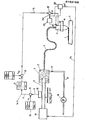
- the figure shows the basic structure of an arrangement which works according to the method according to the invention.
- an application device 3 for example a spray gun
- the robot guides the application device 3 at a certain speed along a path close to the surface of a workpiece 2, on which an adhesive seam is to be applied.
- the application device 3 is connected via a flexible hose 4 to a cylinder 7, in which there is hot or cold adhesive, which is filled in at the beginning of a working cycle via a line 15 and a valve 13 by means of a pump 14.
- a piston 9 is arranged, the drive 10 is designed so that it moves the piston against the adhesive with an adjustable constant pressure.
- the path traversed by the robot is divided into individual path sections, which path sections can be straight or curved sections.
- the time to pass through a section of a path is called a cycle.
- Running through the entire path represents a work cycle.
- a change of direction often takes place at the ends of the path sections.
- the robot usually travels the path at its maximum possible speed. This is usually smaller for curved path sections than for straight ones.
- the application device has a nozzle opening, the average cross section of which can be changed by means of an adjusting device (not shown).
- This adjustment option serves as an actuator for regulating the flow of liquid.
- the adjustment takes place, for example, by rotating or translationally displacing a piston rod, and by measuring the position of this piston rod, a value is obtained for the size of the nozzle opening, which is used as the actual value fi for the flow. In the figure, this measuring element is only symbolically indicated at point 31 tet.
- a comparator 32 the actual flow value f i is compared with a desired flow value f s and the control deviation ⁇ f acts on a controller 33, which controls an adjusting element present in the application device, which is symbolically indicated by 34.
- the setpoint f for the flow is composed of an s basic setpoint f sg and a correction setpoint K, which is added algebraically to the basic setpoint in the summation element 18.
- the basic setpoint is based on a specific viscosity of the liquid and a specific relationship between the nozzle opening and the actuator 34 for the nozzle opening of the application device.
- the correction setpoint K detects and compensates for changes in viscosity and changes in the nozzle opening due to wear, given the position of the actuator.
- the partial paths x i which the piston 9 travels in the cylinder 5 during the passage of the individual cycles of a working cycle of the robot, are measured by means of a symbolically represented path meter 16.
- These values x i are subtracted in a summing element 19 from corresponding target values for the amount of viscous liquid to be applied per cycle.
- These setpoints come from a setpoint generator 20, which is symbolically indicated in the figure for a work cycle consisting of n cycles.
- the difference values x s - x i for the individual cycles form the correction values for the setpoint. They are stored in a memory 21 during the work cycle currently being carried out.
- the correction setpoints obtained in the previous work cycle are added algebraically to the basic setpoint f sg .
- This basic setpoint can also have different values for the individual cycles of the work cycle, which is the case, for example, if the web speed changes during the transition from one cycle to the next cycle, but the seam thickness to be applied is to remain constant.
- the pressure exerted on the piston 9 by the drive arrangement 10 can be increased.
- the signal ⁇ f is expediently brought into effect via the signal line 36 on the drive 10 of the piston via a threshold value element (not shown).
- an adjustment of the nozzle opening is also necessary, for example, if the thickness of the seam is to be changed during the transition from one web section (cycle) to the next web section.
- the time available for this adjustment is extremely short since the robot's dwell status during this transition is very short. For example, it is about 20 ms.
- the adjustment of the nozzle opening can be carried out by means of an electric drive which is operated with clocked direct current, with an overvoltage being used for a short time.
- the method according to the invention is also useful if the liquid flow is not regulated, but only controlled, that is, the actual value f i is not recorded.
Landscapes
- Physics & Mathematics (AREA)
- General Physics & Mathematics (AREA)
- Engineering & Computer Science (AREA)
- Automation & Control Theory (AREA)
- Coating Apparatus (AREA)
- Numerical Control (AREA)
- Feedback Control In General (AREA)
- Flow Control (AREA)
Applications Claiming Priority (2)
| Application Number | Priority Date | Filing Date | Title |
|---|---|---|---|
| DE19853506110 DE3506110A1 (de) | 1985-02-22 | 1985-02-22 | Verfahren zur regelung oder steuerung des flusses einer zaehen fluessigkeit, die von einer maschine selbstaetig als naht aufgetragen wird |
| DE3506110 | 1985-02-22 |
Publications (3)
| Publication Number | Publication Date |
|---|---|
| EP0192166A2 true EP0192166A2 (fr) | 1986-08-27 |
| EP0192166A3 EP0192166A3 (en) | 1988-04-13 |
| EP0192166B1 EP0192166B1 (fr) | 1991-05-08 |
Family
ID=6263204
Family Applications (1)
| Application Number | Title | Priority Date | Filing Date |
|---|---|---|---|
| EP86101719A Expired - Lifetime EP0192166B1 (fr) | 1985-02-22 | 1986-02-11 | Procédé de régulation ou de commande du débit d'un fluide visqueux distribué comme filet |
Country Status (4)
| Country | Link |
|---|---|
| US (1) | US4666732A (fr) |
| EP (1) | EP0192166B1 (fr) |
| JP (1) | JPS61228511A (fr) |
| DE (2) | DE3506110A1 (fr) |
Cited By (3)
| Publication number | Priority date | Publication date | Assignee | Title |
|---|---|---|---|---|
| EP0529686A3 (fr) * | 1986-10-30 | 1993-05-05 | Nordson Corporation | Procédé pour compenser les variations des propriétés d'écoulement d'un fluide distribué par une buse |
| EP3486184A1 (fr) * | 2017-11-02 | 2019-05-22 | Krones AG | Mesure de débit lors de l'alimentation en colle |
| EP4076899B1 (fr) | 2020-07-01 | 2023-05-24 | Actega Artística, S.A.U. | Procédé de commande et système d'injection de fluide à grande vitesse |
Families Citing this family (24)
| Publication number | Priority date | Publication date | Assignee | Title |
|---|---|---|---|---|
| US4922852A (en) * | 1986-10-30 | 1990-05-08 | Nordson Corporation | Apparatus for dispensing fluid materials |
| DE3700212A1 (de) * | 1987-01-07 | 1988-07-21 | Hans Liman | Verfahren und vorrichtung zum dosierten austragen eines viskosen mediums, insbesondere eines klebers |
| DE3728054A1 (de) * | 1987-08-20 | 1989-03-02 | Klatt Helmuth | Verfahren und vorrichtung zum dosieren und auftragen von fluessigen oder pastoesen medien auf einen gegenstand |
| DE3822835A1 (de) * | 1988-07-06 | 1990-03-08 | Josef Schucker | Verfahren und anordnung zum lackieren von werkstueckoberflaechen |
| US5232736A (en) * | 1989-07-24 | 1993-08-03 | Motorola, Inc. | Method for controlling solder printer |
| JP2810456B2 (ja) * | 1989-11-30 | 1998-10-15 | サンスター技研株式会社 | 塗布材のビード切れ検出方法 |
| DE4004198A1 (de) * | 1990-02-12 | 1991-08-14 | Max Planck Gesellschaft | Geraet zum dosierten einfuehren einer substanz in eine anzahl von substraten |
| US5143744A (en) * | 1991-06-19 | 1992-09-01 | Minnesota Mining And Manufacturing Company | Dynamic contact angle measurement system |
| EP0599126B1 (fr) * | 1992-11-20 | 1998-04-15 | Nordson Corporation | Procédé pour surveiller et/ou distribuer des matières sur un substrat |
| US5489337A (en) * | 1993-01-28 | 1996-02-06 | Kabushiki Kaisha Toshiba | Apparatus for applying organic material to semiconductor wafer in which the nozzle opening adjusts in response to data |
| US5499745A (en) * | 1994-02-18 | 1996-03-19 | Nordson Corporation | Apparatus for mixing and dispensing two chemically reactive materials |
| US5687092A (en) * | 1995-05-05 | 1997-11-11 | Nordson Corporation | Method of compensating for changes in flow characteristics of a dispensed fluid |
| AU7262496A (en) * | 1995-10-13 | 1997-04-30 | Nordson Corporation | Flip chip underfill system and method |
| SE508434C2 (sv) * | 1996-02-23 | 1998-10-05 | Scanrex Automation Ab | Metod och system vid dosering |
| US6173864B1 (en) | 1999-04-23 | 2001-01-16 | Nordson Corporation | Viscous material dispensing system and method with feedback control |
| US6541063B1 (en) | 1999-11-04 | 2003-04-01 | Speedline Technologies, Inc. | Calibration of a dispensing system |
| DE10048749A1 (de) | 2000-09-29 | 2002-04-11 | Josef Schucker | Anordnung zum Aufbringen von Klebstoff auf ein Werkstück |
| DE10239351B4 (de) * | 2002-08-28 | 2006-07-27 | Amtec Kistler Gmbh | Vorrichtung zum Auftragen eines Beschichtungsmittels |
| US20040148763A1 (en) * | 2002-12-11 | 2004-08-05 | Peacock David S. | Dispensing system and method |
| DE10361018C9 (de) | 2003-12-23 | 2021-03-04 | QUISS Qualitäts-Inspektionssysteme und Service GmbH | Verfahren zum Erkennen einer auf einem Substrat aufzubringenden Struktur mit mehreren Kameras sowie eine Vorrichtung hierfür |
| CN102830645B (zh) * | 2012-09-26 | 2014-11-12 | 苏州工业园区职业技术学院 | 单轴全自动高速点胶机器人伺服控制系统 |
| DE102015001211A1 (de) | 2015-01-30 | 2015-07-02 | Daimler Ag | Anordnung mit einem Roboter, einem Klebewerkzeug und einer Haltestation |
| CN105005325B (zh) * | 2015-06-16 | 2018-02-23 | 王晓冉 | 对箔式电阻应变计进行自动调阻的方法及自动调阻设备 |
| DE102015121449A1 (de) * | 2015-12-09 | 2017-06-14 | Ba Assembly & Turnkey Systems Gmbh | Verstreicheinheit |
Family Cites Families (7)
| Publication number | Priority date | Publication date | Assignee | Title |
|---|---|---|---|---|
| US1987197A (en) * | 1925-06-30 | 1935-01-08 | Better Packages Inc | Strip serving device |
| US3890922A (en) * | 1974-03-22 | 1975-06-24 | George F Nordenholt | Sealant applying apparatus |
| US4026439A (en) * | 1975-06-18 | 1977-05-31 | Cocks Eric H | Precision fluid dispensing and mixing system |
| US4251566A (en) * | 1978-10-12 | 1981-02-17 | Champion International Corporation | Gum thickness regulator |
| US4367244A (en) * | 1980-10-27 | 1983-01-04 | Oregon Graduate Center For Study And Research | Method for monitoring and controlling the distribution of droplets on a surface |
| US4417934A (en) * | 1980-11-05 | 1983-11-29 | Imperial Group Plc | Monitoring a deposit on a travelling web |
| EP0125771A3 (fr) * | 1983-05-11 | 1985-10-09 | Nordson Corporation | Procédé et appareil pour revêtir les joints de soudure dans des caisses d'automobile |
-
1985
- 1985-02-22 DE DE19853506110 patent/DE3506110A1/de active Granted
-
1986
- 1986-02-11 EP EP86101719A patent/EP0192166B1/fr not_active Expired - Lifetime
- 1986-02-11 DE DE8686101719T patent/DE3679081D1/de not_active Expired - Lifetime
- 1986-02-21 JP JP61037161A patent/JPS61228511A/ja active Pending
- 1986-02-24 US US06/832,434 patent/US4666732A/en not_active Expired - Lifetime
Cited By (5)
| Publication number | Priority date | Publication date | Assignee | Title |
|---|---|---|---|---|
| EP0529686A3 (fr) * | 1986-10-30 | 1993-05-05 | Nordson Corporation | Procédé pour compenser les variations des propriétés d'écoulement d'un fluide distribué par une buse |
| EP3486184A1 (fr) * | 2017-11-02 | 2019-05-22 | Krones AG | Mesure de débit lors de l'alimentation en colle |
| EP4076899B1 (fr) | 2020-07-01 | 2023-05-24 | Actega Artística, S.A.U. | Procédé de commande et système d'injection de fluide à grande vitesse |
| US12208553B2 (en) | 2020-07-01 | 2025-01-28 | Actega Artistica, S.A.U. | Control method and high-speed fluid injection system |
| EP4076899B2 (fr) † | 2020-07-01 | 2026-04-08 | Actega Artística, S.A.U. | Procédé de commande et système d'injection de fluide à grande vitesse |
Also Published As
| Publication number | Publication date |
|---|---|
| DE3679081D1 (de) | 1991-06-13 |
| US4666732A (en) | 1987-05-19 |
| EP0192166B1 (fr) | 1991-05-08 |
| JPS61228511A (ja) | 1986-10-11 |
| DE3506110C2 (fr) | 1987-07-09 |
| DE3506110A1 (de) | 1986-09-04 |
| EP0192166A3 (en) | 1988-04-13 |
Similar Documents
| Publication | Publication Date | Title |
|---|---|---|
| EP0192166B1 (fr) | Procédé de régulation ou de commande du débit d'un fluide visqueux distribué comme filet | |
| EP1854548B1 (fr) | Système de dosage pour un dispositif de revêtement | |
| EP0021182B1 (fr) | Procédé et dispositif pour l'alimentation en peinture des installations de peinture | |
| DE102005014416B4 (de) | Luftservozylindervorrichtung und Steuerverfahren hierfür | |
| DE69723817T2 (de) | Verfahren und system zur abgabe einer viskösen lösung | |
| DE3788729T2 (de) | Vorrichtung und verabreichungssystem flüssiger materialien. | |
| DE9218528U1 (de) | Vorrichtung zum Aufbringen einer pastösen Masse | |
| DE3713999A1 (de) | Verfahren zum selbsttaetigen serienweisen beschichten von werkstuecken | |
| DE3822835A1 (de) | Verfahren und anordnung zum lackieren von werkstueckoberflaechen | |
| DE2053819A1 (de) | Druckluftzylinder-Einheit | |
| DE19625880C2 (de) | Verfahren zum automatischen Maschineneinstellung für die Regelung der Spritzgießgeschwindigkeit | |
| EP0761334B1 (fr) | Machine à cintrer des tubes | |
| EP1270086B1 (fr) | Appareil et procédé pour commander un dispositif de revêtement avec différent buses | |
| DE3435213A1 (de) | Anordnung zur automatischen konstanthaltung der schichtdicke von markierungslinien o.dgl. | |
| DE2544794A1 (de) | Hydraulische presse mit konstantspeicher | |
| EP0806256B1 (fr) | Procédé de contrÔle du coulement de matériau pendant l'emboutissage des pièces de tÔle et dispositif pour la mise en oeuvre du procédé | |
| DE102004031031A1 (de) | Vorrichtung zum Aufbringen von hochviskosen Massen auf eine Werkstückoberfläche | |
| DE2056071A1 (de) | Hydraulische Nachstellvorrichtung fur Werkzeuge | |
| DE102005026374B4 (de) | Verfahren zum Aufbringen von Streifen aus pastösem Material | |
| DE3019998A1 (de) | Einrichtung zur steuerung der ausdehnung des laeppwerkzeuges einer laeppmaschine | |
| DE2101907C3 (de) | Verfahren und Vorrichtung zum Beschichten der Innenwände von Rohren | |
| DE3123257A1 (de) | Hydraulisches steuergeraet | |
| DE102005033292B4 (de) | Vorrichtung zum Auftragen von Kleb- oder Dichtstoffen | |
| DE102005033786B3 (de) | Elektropneumatische Druckmittelmengensteuerung | |
| DE4318844A1 (de) | Verfahren zur zeitabhängigen Regelung einer Dosieranlage für fluide Komponenten und Vorrichtung zur Durchführung des Verfahrens |
Legal Events
| Date | Code | Title | Description |
|---|---|---|---|
| PUAI | Public reference made under article 153(3) epc to a published international application that has entered the european phase |
Free format text: ORIGINAL CODE: 0009012 |
|
| AK | Designated contracting states |
Kind code of ref document: A2 Designated state(s): DE FR GB SE |
|
| PUAL | Search report despatched |
Free format text: ORIGINAL CODE: 0009013 |
|
| AK | Designated contracting states |
Kind code of ref document: A3 Designated state(s): DE FR GB SE |
|
| RAP1 | Party data changed (applicant data changed or rights of an application transferred) |
Owner name: SCHUCKER, JOSEF |
|
| RIN1 | Information on inventor provided before grant (corrected) |
Inventor name: SCHUCKER, JOSEF |
|
| 17P | Request for examination filed |
Effective date: 19880625 |
|
| 17Q | First examination report despatched |
Effective date: 19900730 |
|
| GRAA | (expected) grant |
Free format text: ORIGINAL CODE: 0009210 |
|
| AK | Designated contracting states |
Kind code of ref document: B1 Designated state(s): DE FR GB SE |
|
| REF | Corresponds to: |
Ref document number: 3679081 Country of ref document: DE Date of ref document: 19910613 |
|
| ET | Fr: translation filed | ||
| GBT | Gb: translation of ep patent filed (gb section 77(6)(a)/1977) | ||
| PLBE | No opposition filed within time limit |
Free format text: ORIGINAL CODE: 0009261 |
|
| STAA | Information on the status of an ep patent application or granted ep patent |
Free format text: STATUS: NO OPPOSITION FILED WITHIN TIME LIMIT |
|
| 26N | No opposition filed | ||
| EAL | Se: european patent in force in sweden |
Ref document number: 86101719.2 |
|
| REG | Reference to a national code |
Ref country code: GB Ref legal event code: IF02 |
|
| PGFP | Annual fee paid to national office [announced via postgrant information from national office to epo] |
Ref country code: FR Payment date: 20050113 Year of fee payment: 20 |
|
| PGFP | Annual fee paid to national office [announced via postgrant information from national office to epo] |
Ref country code: GB Payment date: 20050118 Year of fee payment: 20 |
|
| PGFP | Annual fee paid to national office [announced via postgrant information from national office to epo] |
Ref country code: SE Payment date: 20050124 Year of fee payment: 20 |
|
| PGFP | Annual fee paid to national office [announced via postgrant information from national office to epo] |
Ref country code: DE Payment date: 20050215 Year of fee payment: 20 |
|
| PG25 | Lapsed in a contracting state [announced via postgrant information from national office to epo] |
Ref country code: GB Free format text: LAPSE BECAUSE OF EXPIRATION OF PROTECTION Effective date: 20060210 |
|
| REG | Reference to a national code |
Ref country code: GB Ref legal event code: PE20 |
|
| EUG | Se: european patent has lapsed |