EP0192181A2 - Attelle d'abduction pour la décharge de l'articulation d'épaule - Google Patents
Attelle d'abduction pour la décharge de l'articulation d'épaule Download PDFInfo
- Publication number
- EP0192181A2 EP0192181A2 EP86101779A EP86101779A EP0192181A2 EP 0192181 A2 EP0192181 A2 EP 0192181A2 EP 86101779 A EP86101779 A EP 86101779A EP 86101779 A EP86101779 A EP 86101779A EP 0192181 A2 EP0192181 A2 EP 0192181A2
- Authority
- EP
- European Patent Office
- Prior art keywords
- support
- joint
- armrest
- splint according
- abduction
- Prior art date
- Legal status (The legal status is an assumption and is not a legal conclusion. Google has not performed a legal analysis and makes no representation as to the accuracy of the status listed.)
- Granted
Links
Images



Classifications
-
- A—HUMAN NECESSITIES
- A61—MEDICAL OR VETERINARY SCIENCE; HYGIENE
- A61F—FILTERS IMPLANTABLE INTO BLOOD VESSELS; PROSTHESES; DEVICES PROVIDING PATENCY TO, OR PREVENTING COLLAPSING OF, TUBULAR STRUCTURES OF THE BODY, e.g. STENTS; ORTHOPAEDIC, NURSING OR CONTRACEPTIVE DEVICES; FOMENTATION; TREATMENT OR PROTECTION OF EYES OR EARS; BANDAGES, DRESSINGS OR ABSORBENT PADS; FIRST-AID KITS
- A61F5/00—Orthopaedic methods or devices for non-surgical treatment of bones or joints; Nursing devices ; Anti-rape devices
- A61F5/37—Restraining devices for the body or for body parts; Restraining shirts
- A61F5/3715—Restraining devices for the body or for body parts; Restraining shirts for attaching the limbs to other parts of the body
- A61F5/3723—Restraining devices for the body or for body parts; Restraining shirts for attaching the limbs to other parts of the body for the arms
- A61F5/3753—Abduction support
Definitions
- the invention relates to an abduction splint for relieving the shoulder joint by supporting the affected arm in a laterally raised position angled away from the body, consisting of an armrest with a forearm part and optionally an upper arm part, a support supporting the armrest and fastening means for attaching and holding the Support on the patient's body.
- a shoulder strap can be attached to the support (DE-GM 79 15 685, US Pat. No. 4,241,731), which is supported on the patient's shoulder and together with a hip strap with the help of itself crossing bandages is held on the body.
- a bracket or a pad or plate are transferred to the body (DE-OS 30 30 712), wherein the mentioned support part rests against one side of the rib cage and this system, which is required for the proper functioning of such an abduction splint, is usually also provided with a breast or shoulder straps must be secured.
- Abduction splints of the aforementioned type have the disadvantage that they essentially only allow the arm in question to be immobilized due to the arrangement of the fastening means, since movement of the splint relative to the patient's body is not possible or is largely restricted. It follows from this that, although there is a desired immobilization of the arm with relief of the shoulder joint, the patient is not able to practice arm movements by swiveling, spreading, spreading and lifting with the splint attached. This is especially true when the freedom of movement of the arm and the shoulder joint is restricted by shoulder straps and shoulder straps, and these fastening means are also particularly painful if the shoulder joint is injured by pressure cause.
- the object of the invention is to provide an easy-to-use and inexpensive to produce abduction splint, which on the one hand ensures optimal immobilization of the arm and shoulder joint, but on the other hand also gives the patient the opportunity to perform arm movements for exercise and training largely unhindered and controlled.
- the entire load directed from the armrest laterally obliquely downwards to the body is transferred to the patient's body at only one point in the area of the waist, which point can in principle be regarded as a "pivot bearing", which in the case of arbitrary Arm movements allow the armrest to pivot towards the front, back and to the side, without this interfering with the fastening means otherwise provided in the usual abduction splints in the region of the shoulder and / or the rib cage or hindering such arm movements. Otherwise, the arm can also remain absolutely still, since it is due to the anatomical area alone can remain in a stable position supported by the splint, unless the patient deliberately wants to practice arm movements.
- the fastening means can consist of a plate attached to the lower end of the support, which is connected to an item of clothing in the area of the waist, for example via hooks, slits or eyelets.
- the fastening means can consist of a belt attached to the lower end of the support, which is placed around the patient's body in the region of the waist.
- a spring can be arranged between the two support rod parts and act so that the upper support arm part supporting the armrest against and with the action of the spring axially and relative to the lower, here fixed support rod part can be moved.
- one end of the spring will engage the movable support rod part and the other spring end will engage a stop which can be adjusted and fixed longitudinally in the fixed support rod part, so that the length of the support can be adjusted to the height of the patient for the purpose of adapting the abduction splint.
- the degrees of freedom for arm movements can be increased if at least one hinge joint is provided between the fastening means located on the body and the armrest.
- the upper joint body of a double hinge joint can be attached directly to the forearm part of the armrest, while the two parallel joint axes on the middle joint body are to be eccentric to the line of action of the support and the lower joint body is connected to the support.
- Such a crowd Kidney joint will allow the armrest to pivot in two directions and also to raise the armrest relative to the support, in which case the arm should be attached to the armrest with straps.
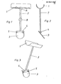
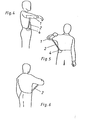
- the rail shown in Figures 1 to 6 has a rela tiv simple and therefore inexpensive construction. It consists of an armrest 1 for the forearm, a support 2 in the form of a rod and fastening means located at the lower end of the support, which are designed as a plate 3 in this example. On this plate there is a hook 4, by means of which a mechanical connection of the rail to an item of clothing is produced, in that, according to FIGS. 4 to 6, the plate 3 is pushed from above between pants and shirt or underwear in the area of the patient's waist that the hook 4 engages over the belt or the waistband.
- Loops or slots 5 can also be provided in the plate 3, through which a belt or belt provided with a closure is inserted, which is placed around the waist and fixes the plate 3 in the intended position. Otherwise, the plate can also be curved to match the shape of the body so that it does not press when worn and the supporting force acting is evenly distributed over the contact area on the body.
- the armrest consists of the forearm part 1 and an upper arm part 6, while the fastening means provided at the bottom of the support 2 consist in a manner known per se of a closable belt 7, which is placed around the patient's body in the region of the waist can be.
- the load caused by the supported arm and the rail is essentially transferred laterally to the body at one point, as in the example described above.
- hinge joints can be arranged between the support 2 and the armrest 1 on the one hand and the belt 7 as a fastening means on the other hand.
- the support 2 designed as a support rod can be subdivided at the area indicated by the circle B and can be designed as shown in FIGS. 8 and 9 in order to be able to change the length of the support.
- the areas A and B can also be found in FIG. 1, so that the exemplary embodiment shown there can also be designed with respect to a hinge joint and a length adjustment of the support in the same way as is described below in connection with the other embodiments.
- a change in length of the support 2 can be achieved so that two support rod parts 2a, 2b, e.g. telescopically interlock and a compression spring 8 inserted between them acts so that the upper, the armrest 1, 6 supporting support rod part 2a against and with the action of this spring can be moved axially and relative to the lower, here fixed support rod part 2b.
- the upper end of the spring 8 engages at the lower end of the support rod part 2a and the lower end of the spring against a stop 9 which is guided in the fixed support rod part 2b and can be fixed with a screw 10 on the support rod part 2b.
- This screw engages with its threaded shaft freely through a longitudinal slot 11 and is screwed into a threaded hole of the stop 9, so that when the screw is tightened the stop 9 is jammed with the inner wall of the support rod part 2b. It is obvious that the effective length of the support 2 can be adjusted with the respective axial position of the stop 9.
- the patient can practice spreading and spreading the arm, the spring 8 determining the force that must be overcome on the one hand during spreading and on the other hand a subsequent downward movement will support spreading movement. If, however, the two support rod parts 2a, 2b are to be rigidly connected by switching off the spring action, a further screw 10a is tightened so that the threaded shaft, which also runs through the longitudinal slot 11 and is screwed into the support rod part 12a, clamps it to the support rod part 2b.
- the patient can move the arm forwards and backwards to a certain extent without difficulty and without hindrance, the armrest 1 being pivoted essentially on a circular arc around the lower end of the support or the support rod 2 .
- at least one hinge joint in particular at least one double hinge joint, is provided between the armrest 1 and the fastening point located on the side of the waist, which pivot movement of the Armrest relative to the support 2 and / or a pivoting movement of the support 2 relative to the fastening means 3, 7 allows.
- the circles A in FIGS. 1 and 7 indicate places where such hinge joints can be arranged, while FIG. 13 represents a practical exemplary embodiment for this.
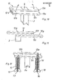
- FIG. 10 shows a double hinge joint 12 which is attached to the upper end of the support 2 and preferably directly below the armrest 1, which is not shown in any more detail.
- the hinge joint consists of three plate-shaped joint bodies, namely the upper joint body 12a rigidly attached to the armrest 1, the middle joint body 12b and the lower joint body 12c, to which the support 2 is rigidly attached below. Otherwise, these joint bodies are above the two axes 12d and
- the joint body 12a can thus be pivoted counterclockwise about the axis 12d, while the joint bodies 12a, 12b can be pivoted clockwise together about the axis 12e. Furthermore, the joint body 12a can be raised in parallel to the fixed joint body 12c. Finally, depending on the direction of an arbitrary arm movement, these adjustment movements can also overlap and take place in the opposite direction until the joint bodies again assume the stable position shown. This position is stable because the two parallel joint axes 12d, 12e are eccentric to the line of action of the support 2.
- the force required to open the parts of the hinge joint 12 and to be exerted by the arm and shoulder muscles can also be set as a function of the respectively desired pivoting direction of the arm if the two joint axes are relative to one another and / or relative to the line of action or imaginary extension the support 2 can be adjusted.
- the middle joint body can be divided, so that the joint 12 according to FIG. 11 consists of two individual hinges, each with two joint bodies, the two middle neighboring joint bodies 12f, 12g being connected to one another, but being able to be displaced relative to one another. This can be achieved, for example, by a form-fitting guide engagement of these two joint bodies.
- FIG. 12 shows a solution for this.
- a threaded bolt 13 is guided through an elongated hole in the lower joint body 12c and articulated on the middle articulated body 12b, while a threaded bolt 14 articulated on the upper articulated body 12a runs through elongated holes in the articulated bodies 12c, 12d.
- Compressed springs 15, 16 sit concentrically on these threaded bolts, which, as shown, are supported with their upper ends on the joint body 12c and with their lower ends on wing nuts.
- the wing nuts 17, 18 can be used to manually adjust the pressure force with which the joint bodies are held together and which must be exerted by the muscular strength when practicing arm movements in order to counteract the joint body 12a in the counterclockwise direction from the joint body 12b or when the arm is pivoted To be able to lift clockwise from the joint body 12c by pivoting.
- FIG. 13 shows an abduction rail, in which a hinge joint 12 is provided at the upper and lower end of the support 2.
- the arrows shown indicate the directions in which the support 2 is pivoted with the lower hinge joint 12 and the forearm part 1 of the armrest can be pivoted about the hinge joint 12 located on the support 2 and raised relative to the support 2.
- FIGS. 14 and 15 show a special embodiment for a joint with which the support at the lower end can be detachably connected to the plate 3.
- This is a ball joint, the ball 19 of which is connected to the support 2 via a web 20.
- the ball rests in a trough of the holder 21 fastened to the plate 3 in such a way that the support with the armrest can be pivoted relative to the plate and thus to the patient's body.
- existing holder 21 has two arms 21a, 21b, between which an open top insertion slot 22 is formed, in which the web 20 fits. According to FIG. 15, the holder has a distance from the plate 3 at the upper end which is less than the diameter of the joint ball 19.
- the articulated connection is made so that the articulated ball 19 with the web 20 aligned with the slot 22 is placed on top of the holder 21 and pressed down, so that the ball reaches the aforementioned cavity while the holder is spreading from the plate 3, the Web is led down through the slot.
Landscapes
- Health & Medical Sciences (AREA)
- Nursing (AREA)
- Orthopedic Medicine & Surgery (AREA)
- Engineering & Computer Science (AREA)
- Biomedical Technology (AREA)
- Heart & Thoracic Surgery (AREA)
- Vascular Medicine (AREA)
- Life Sciences & Earth Sciences (AREA)
- Animal Behavior & Ethology (AREA)
- General Health & Medical Sciences (AREA)
- Public Health (AREA)
- Veterinary Medicine (AREA)
- Orthopedics, Nursing, And Contraception (AREA)
- Pens And Brushes (AREA)
Priority Applications (1)
| Application Number | Priority Date | Filing Date | Title |
|---|---|---|---|
| AT86101779T ATE63053T1 (de) | 1985-02-18 | 1986-02-12 | Abduktionsschiene zum entlasten des schultergelenkes. |
Applications Claiming Priority (2)
| Application Number | Priority Date | Filing Date | Title |
|---|---|---|---|
| DE3505528 | 1985-02-18 | ||
| DE19853505528 DE3505528A1 (de) | 1985-02-18 | 1985-02-18 | Abduktionsschiene zum entlasten des schultergelenkes |
Publications (3)
| Publication Number | Publication Date |
|---|---|
| EP0192181A2 true EP0192181A2 (fr) | 1986-08-27 |
| EP0192181A3 EP0192181A3 (en) | 1987-09-16 |
| EP0192181B1 EP0192181B1 (fr) | 1991-05-02 |
Family
ID=6262818
Family Applications (1)
| Application Number | Title | Priority Date | Filing Date |
|---|---|---|---|
| EP86101779A Expired - Lifetime EP0192181B1 (fr) | 1985-02-18 | 1986-02-12 | Attelle d'abduction pour la décharge de l'articulation d'épaule |
Country Status (3)
| Country | Link |
|---|---|
| EP (1) | EP0192181B1 (fr) |
| AT (1) | ATE63053T1 (fr) |
| DE (2) | DE3505528A1 (fr) |
Cited By (8)
| Publication number | Priority date | Publication date | Assignee | Title |
|---|---|---|---|---|
| FR2602674A1 (fr) * | 1986-08-14 | 1988-02-19 | Dumoutier Gerard | Attelle orthopedique |
| EP0727198A1 (fr) * | 1995-02-16 | 1996-08-21 | Protectair Limited | Orthèse pour la partie supérieure du corps |
| US9204989B2 (en) | 2013-09-06 | 2015-12-08 | Universite De Montreal | Dynamic shoulder orthosis with rehabilitating adduction |
| US9918854B2 (en) | 2011-03-16 | 2018-03-20 | Smith & Nephew, Inc. | Compound angle implant |
| CN110742715A (zh) * | 2019-11-28 | 2020-02-04 | 横县人民医院 | 防止放疗后腋窝溃烂的手臂支架 |
| CN113164275A (zh) * | 2018-11-05 | 2021-07-23 | 奥托博克欧洲股份两合公司 | 用于支持使用者的至少一个臂的装置 |
| JP2022054479A (ja) * | 2020-09-27 | 2022-04-07 | 太陽パーツ株式会社 | サポートウェア |
| US12370073B2 (en) | 2022-04-26 | 2025-07-29 | Gen3 Medical, LLC | Device for immobilizing a shoulder |
Families Citing this family (2)
| Publication number | Priority date | Publication date | Assignee | Title |
|---|---|---|---|---|
| DE19911834A1 (de) * | 1999-03-17 | 2000-10-05 | Felix Becker | Vorrichtung zur Abstützung eines Unterarmes |
| DE102017112436B4 (de) * | 2017-06-06 | 2019-05-29 | Ottobock Se & Co. Kgaa | Vorrichtung zum Unterstützen wenigstens eines Armes eines Benutzers |
Family Cites Families (8)
| Publication number | Priority date | Publication date | Assignee | Title |
|---|---|---|---|---|
| US1295297A (en) * | 1917-10-20 | 1919-02-25 | John Rollin French | Surgical splint. |
| DE582933C (de) * | 1932-01-03 | 1933-08-25 | Heinrich C Ulrich | Am Koerper zu befestigende Armlagerungsschiene mit Schultergelenk |
| US2661000A (en) * | 1951-06-25 | 1953-12-01 | William E Gazeley | Surgical splint |
| US3952733A (en) * | 1975-04-23 | 1976-04-27 | Williams Ester B | Arm support |
| SE418452B (sv) * | 1978-02-08 | 1981-06-09 | Holmgren Ortoped | Styranordning for underarmsortoser och liknande |
| US4241731A (en) * | 1978-05-11 | 1980-12-30 | Pauley James H | Universal arm support |
| JPS5540211A (en) * | 1978-09-13 | 1980-03-21 | Toyota Motor Corp | Exhaust gas recirculating control valve for diesel engine |
| DE3030712A1 (de) * | 1980-08-14 | 1982-03-18 | Blanc Gmbh & Co, 7519 Oberderdingen | Abduktionsschiene |
-
1985
- 1985-02-18 DE DE19853505528 patent/DE3505528A1/de active Granted
-
1986
- 1986-02-12 EP EP86101779A patent/EP0192181B1/fr not_active Expired - Lifetime
- 1986-02-12 DE DE8686101779T patent/DE3678974D1/de not_active Expired - Lifetime
- 1986-02-12 AT AT86101779T patent/ATE63053T1/de not_active IP Right Cessation
Cited By (9)
| Publication number | Priority date | Publication date | Assignee | Title |
|---|---|---|---|---|
| FR2602674A1 (fr) * | 1986-08-14 | 1988-02-19 | Dumoutier Gerard | Attelle orthopedique |
| EP0264303A1 (fr) * | 1986-08-14 | 1988-04-20 | Dumoutier, Gérard Michel | Attelle orthopédique |
| EP0727198A1 (fr) * | 1995-02-16 | 1996-08-21 | Protectair Limited | Orthèse pour la partie supérieure du corps |
| US9918854B2 (en) | 2011-03-16 | 2018-03-20 | Smith & Nephew, Inc. | Compound angle implant |
| US9204989B2 (en) | 2013-09-06 | 2015-12-08 | Universite De Montreal | Dynamic shoulder orthosis with rehabilitating adduction |
| CN113164275A (zh) * | 2018-11-05 | 2021-07-23 | 奥托博克欧洲股份两合公司 | 用于支持使用者的至少一个臂的装置 |
| CN110742715A (zh) * | 2019-11-28 | 2020-02-04 | 横县人民医院 | 防止放疗后腋窝溃烂的手臂支架 |
| JP2022054479A (ja) * | 2020-09-27 | 2022-04-07 | 太陽パーツ株式会社 | サポートウェア |
| US12370073B2 (en) | 2022-04-26 | 2025-07-29 | Gen3 Medical, LLC | Device for immobilizing a shoulder |
Also Published As
| Publication number | Publication date |
|---|---|
| DE3505528C2 (fr) | 1987-10-15 |
| DE3678974D1 (de) | 1991-06-06 |
| DE3505528A1 (de) | 1986-08-21 |
| EP0192181A3 (en) | 1987-09-16 |
| ATE63053T1 (de) | 1991-05-15 |
| EP0192181B1 (fr) | 1991-05-02 |
Similar Documents
| Publication | Publication Date | Title |
|---|---|---|
| DE3854651T2 (de) | Gelenkverbindung für orthopädische Kniestütze. | |
| DE3710233C2 (fr) | ||
| DE102005025159A1 (de) | Künstliches Bein mit Sitzbeinunterstützung | |
| EP0362528B1 (fr) | Coussin d'abduction | |
| EP0192181B1 (fr) | Attelle d'abduction pour la décharge de l'articulation d'épaule | |
| DE3436120C1 (de) | Trainingsgeraet zum Trainieren der Oberschenkel- und Wadenmuskeln | |
| DE3235134C2 (de) | Orthopädische Fußschiene mit schwenkbaren Schuhaufnahmeplatten | |
| DE2724586A1 (de) | Orthopaedische schiene zur stuetzung des kniegelenkes | |
| DE19652416A1 (de) | Verfahren und orthopädisches Stützkorsett zur Stützung des menschlichen Oberkörpers in gebeugter Haltung | |
| DE2152408B2 (de) | Physiologisches kniegelenk fuer eine rohrskelett-prothese | |
| EP1292366A2 (fr) | Dispositif pour traiter et faire travailler les articulations du corps humain | |
| CH650658A5 (en) | Therapy couch | |
| DE1147711B (de) | Abduktionsschiene | |
| DE60209459T2 (de) | Schulterblatt/Oberarm-Rehabilitationsgerät | |
| DE20120285U1 (de) | Trainingsgerät für den menschlichen Körper | |
| DE4313494A1 (de) | Vorrichtung zum Heben einer bettlägerigen oder in der Beweglichkeit eingeschränkten Person | |
| DE10152769B4 (de) | Abduktor- und Adduktor-Übungsgeräte zur Stärkung der Muskulatur und zur selektiven Beherrschung der Muskelmotorik | |
| DE4415604B4 (de) | Orthese zur Ruhigstellung der Lendenwirbelsäule | |
| DE8912344U1 (de) | Dynamische Abduktionsschiene | |
| EP3873390B1 (fr) | Orthèse de genou | |
| DE3915079C2 (de) | Gerät zum körperlichen Training | |
| DE2532285C2 (de) | Auf eine Liegeflache aufzustellende Unterschenkelstutze | |
| DE1937829C3 (de) | Tisch zur Spondylo- oder Vertebraltherapie | |
| DE102021131813A1 (de) | Hüftabduktionsorthese und Orthesensystem | |
| EP2221092A1 (fr) | Dispositif orthopédique |
Legal Events
| Date | Code | Title | Description |
|---|---|---|---|
| PUAI | Public reference made under article 153(3) epc to a published international application that has entered the european phase |
Free format text: ORIGINAL CODE: 0009012 |
|
| AK | Designated contracting states |
Kind code of ref document: A2 Designated state(s): AT BE CH DE FR GB IT LI NL SE |
|
| PUAL | Search report despatched |
Free format text: ORIGINAL CODE: 0009013 |
|
| RHK1 | Main classification (correction) |
Ipc: A61F 5/04 |
|
| AK | Designated contracting states |
Kind code of ref document: A3 Designated state(s): AT BE CH DE FR GB IT LI NL SE |
|
| 17P | Request for examination filed |
Effective date: 19880114 |
|
| RAP1 | Party data changed (applicant data changed or rights of an application transferred) |
Owner name: JACOBSEN, UWE, DR. MED. |
|
| RIN1 | Information on inventor provided before grant (corrected) |
Inventor name: JACOBSEN, UWE, DR. MED. |
|
| 17Q | First examination report despatched |
Effective date: 19890824 |
|
| GRAA | (expected) grant |
Free format text: ORIGINAL CODE: 0009210 |
|
| AK | Designated contracting states |
Kind code of ref document: B1 Designated state(s): AT BE CH DE FR GB IT LI NL SE |
|
| PG25 | Lapsed in a contracting state [announced via postgrant information from national office to epo] |
Ref country code: IT Free format text: LAPSE BECAUSE OF FAILURE TO SUBMIT A TRANSLATION OF THE DESCRIPTION OR TO PAY THE FEE WITHIN THE PRE;WARNING: LAPSES OF ITALIAN PATENTS WITH EFFECTIVE DATE BEFORE 2007 MAY HAVE OCCURRED AT ANY TIME BEFORE 2007. THE CORRECT EFFECTIVE DATE MAY BE DIFFERENT FROM THE ONE RECORDED.SCRIBED TIME-LIMIT Effective date: 19910502 Ref country code: SE Effective date: 19910502 Ref country code: NL Effective date: 19910502 Ref country code: FR Effective date: 19910502 Ref country code: BE Effective date: 19910502 Ref country code: GB Effective date: 19910502 |
|
| REF | Corresponds to: |
Ref document number: 63053 Country of ref document: AT Date of ref document: 19910515 Kind code of ref document: T |
|
| REF | Corresponds to: |
Ref document number: 3678974 Country of ref document: DE Date of ref document: 19910606 |
|
| EN | Fr: translation not filed | ||
| NLV1 | Nl: lapsed or annulled due to failure to fulfill the requirements of art. 29p and 29m of the patents act | ||
| GBV | Gb: ep patent (uk) treated as always having been void in accordance with gb section 77(7)/1977 [no translation filed] | ||
| PG25 | Lapsed in a contracting state [announced via postgrant information from national office to epo] |
Ref country code: AT Effective date: 19920212 |
|
| PG25 | Lapsed in a contracting state [announced via postgrant information from national office to epo] |
Ref country code: CH Effective date: 19920229 Ref country code: LI Effective date: 19920229 |
|
| PLBE | No opposition filed within time limit |
Free format text: ORIGINAL CODE: 0009261 |
|
| STAA | Information on the status of an ep patent application or granted ep patent |
Free format text: STATUS: NO OPPOSITION FILED WITHIN TIME LIMIT |
|
| 26N | No opposition filed | ||
| REG | Reference to a national code |
Ref country code: CH Ref legal event code: PL |
|
| PGFP | Annual fee paid to national office [announced via postgrant information from national office to epo] |
Ref country code: DE Payment date: 19940426 Year of fee payment: 9 |
|
| PG25 | Lapsed in a contracting state [announced via postgrant information from national office to epo] |
Ref country code: DE Effective date: 19951101 |